EP0056665A1 - Récipient empilable pour plants - Google Patents
Récipient empilable pour plants Download PDFInfo
- Publication number
- EP0056665A1 EP0056665A1 EP82200011A EP82200011A EP0056665A1 EP 0056665 A1 EP0056665 A1 EP 0056665A1 EP 82200011 A EP82200011 A EP 82200011A EP 82200011 A EP82200011 A EP 82200011A EP 0056665 A1 EP0056665 A1 EP 0056665A1
- Authority
- EP
- European Patent Office
- Prior art keywords
- holder
- holder according
- corner posts
- base plate
- stackable
- Prior art date
- Legal status (The legal status is an assumption and is not a legal conclusion. Google has not performed a legal analysis and makes no representation as to the accuracy of the status listed.)
- Granted
Links
- 125000006850 spacer group Chemical group 0.000 claims description 29
- 238000009423 ventilation Methods 0.000 claims description 2
- 230000001154 acute effect Effects 0.000 claims 1
- 238000001746 injection moulding Methods 0.000 claims 1
- 239000002184 metal Substances 0.000 claims 1
- 238000005520 cutting process Methods 0.000 abstract description 13
- 241000047428 Halter Species 0.000 description 10
- 241000196324 Embryophyta Species 0.000 description 2
- XEEYBQQBJWHFJM-UHFFFAOYSA-N Iron Chemical compound [Fe] XEEYBQQBJWHFJM-UHFFFAOYSA-N 0.000 description 2
- 238000002347 injection Methods 0.000 description 2
- 239000007924 injection Substances 0.000 description 2
- 238000012432 intermediate storage Methods 0.000 description 2
- 238000004382 potting Methods 0.000 description 2
- 230000003014 reinforcing effect Effects 0.000 description 2
- 239000002689 soil Substances 0.000 description 2
- 238000003860 storage Methods 0.000 description 2
- 241000278323 Daphne cneorum Species 0.000 description 1
- 238000004026 adhesive bonding Methods 0.000 description 1
- 229910052742 iron Inorganic materials 0.000 description 1
- 239000007788 liquid Substances 0.000 description 1
- 239000000463 material Substances 0.000 description 1
- 230000002787 reinforcement Effects 0.000 description 1
- 239000007921 spray Substances 0.000 description 1
Images


Classifications
-
- B—PERFORMING OPERATIONS; TRANSPORTING
- B65—CONVEYING; PACKING; STORING; HANDLING THIN OR FILAMENTARY MATERIAL
- B65D—CONTAINERS FOR STORAGE OR TRANSPORT OF ARTICLES OR MATERIALS, e.g. BAGS, BARRELS, BOTTLES, BOXES, CANS, CARTONS, CRATES, DRUMS, JARS, TANKS, HOPPERS, FORWARDING CONTAINERS; ACCESSORIES, CLOSURES, OR FITTINGS THEREFOR; PACKAGING ELEMENTS; PACKAGES
- B65D21/00—Nestable, stackable or joinable containers; Containers of variable capacity
- B65D21/02—Containers specially shaped, or provided with fittings or attachments, to facilitate nesting, stacking, or joining together
- B65D21/04—Open-ended containers shaped to be nested when empty and to be superposed when full
- B65D21/048—Identical stackable containers specially adapted for retaining the same orientation when nested, e.g. the upper container being fixed or slightly rotatable during the nesting operation
-
- A—HUMAN NECESSITIES
- A01—AGRICULTURE; FORESTRY; ANIMAL HUSBANDRY; HUNTING; TRAPPING; FISHING
- A01G—HORTICULTURE; CULTIVATION OF VEGETABLES, FLOWERS, RICE, FRUIT, VINES, HOPS OR SEAWEED; FORESTRY; WATERING
- A01G9/00—Cultivation in receptacles, forcing-frames or greenhouses; Edging for beds, lawn or the like
- A01G9/02—Receptacles, e.g. flower-pots or boxes; Glasses for cultivating flowers
- A01G9/029—Receptacles for seedlings
- A01G9/0295—Units comprising two or more connected receptacles
-
- B—PERFORMING OPERATIONS; TRANSPORTING
- B65—CONVEYING; PACKING; STORING; HANDLING THIN OR FILAMENTARY MATERIAL
- B65D—CONTAINERS FOR STORAGE OR TRANSPORT OF ARTICLES OR MATERIALS, e.g. BAGS, BARRELS, BOTTLES, BOXES, CANS, CARTONS, CRATES, DRUMS, JARS, TANKS, HOPPERS, FORWARDING CONTAINERS; ACCESSORIES, CLOSURES, OR FITTINGS THEREFOR; PACKAGING ELEMENTS; PACKAGES
- B65D21/00—Nestable, stackable or joinable containers; Containers of variable capacity
- B65D21/02—Containers specially shaped, or provided with fittings or attachments, to facilitate nesting, stacking, or joining together
Definitions
- the invention relates to a stackable holder for seedlings which comprises an essentially rectangular base plate with vertical boundary walls for the seedlings attached thereon and four spacers arranged near the corner points.
- Holders of the type described above are used for growing plants from seeds or cuttings.
- the holders play a role during the entire planting cycle, which extends from the filling station to fill the holder with the planting medium until the adult plants or cuttings are planted out in pots or in the open field and the empty holders are returned to the filling station.
- the empty holders transported in stack form are filled with planting medium in a filling station.
- the planting medium is consistently in the form of tablets made of pressed potting soil that can be broken into square blocks. The tablets are placed in the holders removed from the stack.
- the tablets can be pushed into the holder without having to remove them from the stack.
- the stacked holders are transported to a location, possibly via intermediate storage, where e.g. Flower cuttings are planted in the planting medium. From here the stacks of holders are transported to a room where the boxes are placed next to each other in a field. In this air-conditioned room, in which the cuttings receive enough light and can be sprayed excellently, there are excellent conditions for the growth and especially for the rooting of the cuttings.
- the holders are stacked again in order to be sent to the customers who use the cuttings e.g. transplant into the open field and cultivate them further to the flowers suitable for retail sale.
- the empty holders are stacked and possibly transported back to the filling station via intermediate storage.
- the purpose of the invention is to provide a holder without the disadvantage mentioned.
- the holder is equipped with first spacers for straight stacking of holders in a first position of use with a small stacking distance and with second spacers for straight stacking of holders in a second position of use with a large stacking distance.
- 'Straight stacking here means that the long and short sides of the holder form vertical surfaces, so that a block-shaped stack is created.
- the large or small stacking distance can be used as desired, the small stacking distance being selected if there are no or low cuttings in the holders or if the holders are completely empty.
- the first spacers are formed by wall parts which are directed vertically downwards around the base plate and which are supported in a stack with their underside on the upper side of the parts of the base plate which project beyond the boundary walls.
- the second spacers consist of four fold-down corner posts, which are located in a horizontal position in the niche-shaped recesses, which extend from the four corner posts of the base plate along the long sides and are formed by lower design of the base plate, two corner posts each on the narrow side of the base plate Legs of a substantially U-shaped bracket are formed, of which a central part of the base is bent to a plane which is perpendicular to the plane extending through the legs and the parts of the base adjacent to the legs as hinge axes in the under Base plate lying along the narrow side of the hinge cavities.
- first spacers are formed by the boundary walls on the base plate and the second spacers are formed by four hollow, tapered corner posts, two of which are on the ends of the long boundary walls on one side of the holder and two Corner posts are attached at a certain distance from the other ends of the long boundary walls and, in addition to the spacers, cavities are provided on the underside of the boundary walls, into which the upper ends of the corner posts fit, so that the corner posts slide into one another in the first use position when stacking and when Stacking in the second position of use, the holders being arranged offset from one another by 180 °, the upper ends of the corner posts of a holder being received by the cavities of the holder stacked thereon located next to the corner posts.
- the boundary walls can be hollow, i.e. double-walled.
- a further embodiment according to the invention is a holder in which the first spacers are formed by the boundary walls on the base plate and the second spacers are formed by four corner posts arranged obliquely to a narrow side of the holder and near the corner points of the holder when stacking in the first position of use move along each other and where cavities are provided vertically below the upper ends of the corner posts on the underside of the boundary walls, so that when stacking in the second position of use the upper ends of the corner posts get into the cavities.
- a short boundary wall In order to make it easier to fill the holder with planting medium, it is advantageous to omit a short boundary wall.
- a short side wall is provided with openings through which an ejection device can be inserted.
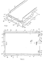
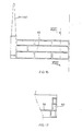
- FIGS. 1 to 9 A first embodiment of a holder according to the invention is shown in FIGS. 1 to 9, with FIG. 1 serving primarily to arrange and operate the bracket used in this embodiment and bent in a special shape, as shown in FIG. 5 to illustrate.
- the holder in Fig. 1 consists of a rectangular base plate 1, on which the boundary walls 2, 3 and 4 are located on three sides, of which the wall 4 is shown in Fig. 2, an upper view of the holder.
- the boundary walls for the planting material to be introduced are located at a certain distance from the outer circumference of the base plate, leaving the standing surfaces 5, 6, 7 and 8 free, on which the wall parts 9, 10, 11 and 12 which are directed vertically downward are used as first spacers when stacked in the first position of use support small stacking distance.
- the bent part of the base consisting of the two short legs 28 and 29 as well as a horizontal part 30, lies on the inside of the horizontal wall part 12 when the corner posts are folded down, while this part of the bracket rests on the underside of the base plate in the case of vertically arranged corner posts, whereby the horizontal part 30 is clamped behind a resilient clamping device 31, as indicated in FIG. 6.
- a resilient clamping device 31 On the underside of the holder are the cavities 32, 33, 34 and 35 at the four corner points, which receive the upper ends of the corner posts in the second position of use, as shown in FIG. 9 for a corner point.
- FIG. 1 shows a section along the line VI-VI in FIG. 2, more details being visible, such as the perforation 36 in the base plate 1, the reinforcing ribs 37 and the ventilation openings 38 in the vertical wall parts and the shape of the wall 12, in which there are hinge recesses and the location where the horizontal part 30 or 30 'of the bracket is accommodated in the first or second position of use.
- FIG. 7 shows half of a narrow side wall in a side view and FIG.
- FIG. 8 shows a section through the essential parts of a hinge cavity along the line VIII-VIII in FIG. 7.
- the wall 12 in the hinge cavity 27 is formed by an inwardly lying part 39 of the wall 12, which deviates outwards on the upper side, namely by the horizontal part 40, which carries a raised part 41 on the outside.
- the upper surface of the part 39 and the raised part 41 define a circumference of the hinge cavity in which the hinge axis of the bracket can be accommodated.
- the resilient lip 42 is fastened on one side to the base plate and is surrounded in the plane of the base plate by the curved opening 43 (see FIG. 2), as a result of which the lip deflects somewhat upwards and to the side from the narrow side when the clip is inserted can.
- the above-described holder also offers the possibility that the second spacers can be placed completely horizontally. This is important if the holders, filled with planting medium and cuttings, are laid out in a field. The cuttings are then easily accessible from all sides for light and spray liquid, since no place is covered by high spacers.
- the stirrups are preferably bent from strong iron wire.
- the hinge cavity on the outside of the holder can be closed with a bridge part, which is attached to the holder with a snap connection or by gluing.
- This bridge part is shown in Fig. 8A.
- Figure 8A shows the same section as Fig. 8, but omitting the resilient lip 42 and the raised part 41, in whose place the bridge part 42 'has stepped.
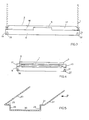
- FIGS. 10 to 13 a holder with a rectangular base plate 45 and three essentially hollow boundary walls 46, 47 and 48 is shown in FIGS. 10 to 13.
- the two spacers are hollow, conical corner posts are formed which, when the holders are stacked one above the other in the same orientation, slide into one another until the underside of the boundary walls is supported on the upper side of the boundary walls of the holder below, as indicated in FIG. 12.
- the boundary walls form the first spacers here.
- the boundary walls 47 and 48 also include the wall parts 52 and 53 which are not hollow in this case and which are located next to the corner posts, which protrude at a certain distance with the feet 54 and 55 under the holder and which are stacked in the first position of use between the boundary walls leave a gap in the boxes in the stack.
- the feet also offer the advantage that the hollow corner posts are above the floor when the holder is placed on the floor and therefore less dirty.
- Wall 48 is also provided with the wall parts 52 and 53 and the feet 54 and 55 discussed. In the bottom of the feet 54 and 55 there are cavities 56 and 57, into which the upper parts of the corner posts 59 and 60 fit.
- the successive brackets each being arranged horizontally offset by 180 ° with respect to one another, the upper ends of the corner posts are received by the cavities in the feet. Since the base of the feet is exactly the same length as the base of the tapered corner posts on the top of the boundary walls, the holders can be stacked one above the other to form a block-shaped stack. 13 shows how the upper part of a corner post is received in the cavity 56 of a foot 54 on the underside of the one wall part 52 formed with a simple wall. For reinforcement, just above the arched Hollow 56 a vertical stiffening rib 58 may be attached to the outside of the boundary wall.
- the holder can also be designed with two short boundary walls.
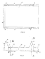
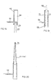
- FIGS. 14 to 20 A third embodiment of the holder according to the invention is shown in FIGS. 14 to 20; 14 shows the top view thereof.
- the holder has a rectangular bottom 59, a short boundary wall 60 and two long boundary walls 61 and 62.
- the holder can also be provided with two short side walls.
- the walls 61 and 62 are essentially hollow.
- Two pairs of corner posts 63 and 64 serving as second spacers are located on the long side walls, all of which are arranged in the same direction at the same angle as shown in FIG.
- the angle of inclination of the center lines, as indicated for a corner post 63 at 65, is 35 °.
- ribs 66 and 67 arranged obliquely in the wall cavity, which together with the wall 62 or 61 include recesses into which the corner posts fit when a holder is in the first position of use on another Holder is placed.
- the upper holder is placed obliquely downwards on the holder below.
- this direction should run from the top left to the bottom right.
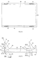
- the corner posts slide along each other in such a way that the brackets just lie on top of each other. 15 protrudes beyond wall 62, this is not necessary if shorter corner posts are chosen. In this case, the top wall can be closed.
- the inclusion of a corner post in the wall cavity is illustrated again in FIG. 19, where the wall parts 70 and 71 together form the wall 62.
- the corner posts are hollow in the drawing (see Fig. 20); however, it is also possible to omit the wall parts located on the outside of the holder and to reinforce the corner posts by means of ribs.
- the corner posts When stacking in the first position of use, the corner posts move along each other until the undersides of the boundary walls of a holder rest on the upper sides of the boundary walls of the holder below, so that the boundary walls serve as first spacers.
- the boundary walls include the non-double wall parts 72 and 73, which are provided with feet 74 and 75 on the underside.
- the short boundary wall 60 one of which is shown in FIG. 16 Right view is shown, has openings (83) and is also reinforced by horizontal and vertical ribs.
- the openings 83 can not only serve as a handle, but are primarily attached to carry out a sliding mechanism that empties the holder to the opposite side (without a boundary wall).
- the last-described holder has the considerable advantage that all holders are accessible from the same side in both positions of use. They can be easily moved from the first to the second position of use and vice versa, by simply performing oblique and horizontal movements of the holder.
- the described holder according to the invention can be injection molded in one piece from plastic.
- the external dimensions of the holders are preferably 600 mm or 400 mm, since the holders currently used have these dimensions.
- the described holders according to the invention preferably have base plates reinforced by ribs.
Landscapes
- Engineering & Computer Science (AREA)
- Mechanical Engineering (AREA)
- Life Sciences & Earth Sciences (AREA)
- Environmental Sciences (AREA)
- Cultivation Receptacles Or Flower-Pots, Or Pots For Seedlings (AREA)
- Stackable Containers (AREA)
Priority Applications (1)
| Application Number | Priority Date | Filing Date | Title |
|---|---|---|---|
| AT82200011T ATE15352T1 (de) | 1981-01-10 | 1982-01-07 | Stapelbarer behaelter fuer pflanzgut. |
Applications Claiming Priority (2)
| Application Number | Priority Date | Filing Date | Title |
|---|---|---|---|
| NL8100096A NL8100096A (nl) | 1981-01-10 | 1981-01-10 | Stapelbare houder voor kweekgoed. |
| NL8100096 | 1981-01-10 |
Publications (2)
| Publication Number | Publication Date |
|---|---|
| EP0056665A1 true EP0056665A1 (fr) | 1982-07-28 |
| EP0056665B1 EP0056665B1 (fr) | 1985-09-04 |
Family
ID=19836839
Family Applications (1)
| Application Number | Title | Priority Date | Filing Date |
|---|---|---|---|
| EP82200011A Expired EP0056665B1 (fr) | 1981-01-10 | 1982-01-07 | Récipient empilable pour plants |
Country Status (4)
| Country | Link |
|---|---|
| EP (1) | EP0056665B1 (fr) |
| AT (1) | ATE15352T1 (fr) |
| DE (1) | DE3265917D1 (fr) |
| NL (1) | NL8100096A (fr) |
Cited By (6)
| Publication number | Priority date | Publication date | Assignee | Title |
|---|---|---|---|---|
| EP0657096A1 (fr) * | 1993-12-11 | 1995-06-14 | Günter Dümmen | Plateau de culture pour l'élevage de plantules |
| DE4425569A1 (de) * | 1994-07-20 | 1996-01-25 | Berolina Kunststoff | Stapelkasten |
| DE29600977U1 (de) * | 1996-01-20 | 1996-03-07 | Franz Delbrouck GmbH, 58710 Menden | Transportkasten aus Kunststoff |
| US5609254A (en) * | 1992-02-15 | 1997-03-11 | Mckechnie Uk Ltd. | Container |
| NL1009922C2 (nl) * | 1998-08-21 | 2000-02-22 | Tic Dev B V I O | Transportmiddel voor losse producten. |
| WO2023078964A1 (fr) * | 2021-11-03 | 2023-05-11 | Kalera Gmbh | Système de support pour la culture de plantes comprenant une pluralité de supports |
Citations (10)
| Publication number | Priority date | Publication date | Assignee | Title |
|---|---|---|---|---|
| GB666355A (en) * | 1949-08-08 | 1952-02-13 | Walter Lionel Jelf Pomfret | Improvements in plant propagating devices |
| US3172542A (en) * | 1963-05-10 | 1965-03-09 | Benner Nawman Inc | Folding tray construction |
| GB998401A (en) * | 1962-10-05 | 1965-07-14 | Hy Whittle Ltd | Improvements in or relating to wire trays |
| US3204778A (en) * | 1962-06-15 | 1965-09-07 | Benner Nawman Inc | Folding tray construction |
| US3405810A (en) * | 1966-09-22 | 1968-10-15 | Mid West Metallic Prod Inc | Tierable and nestable receptacle |
| US3443722A (en) * | 1966-01-21 | 1969-05-13 | Nosco Plastics | Plastic case |
| GB1253561A (en) * | 1969-03-27 | 1971-11-17 | Cie D Installation De Dev Et D | Dish tray |
| US3648909A (en) * | 1970-08-26 | 1972-03-14 | Bishop Wisecarver Corp | Carrying tray |
| NL7606555A (nl) * | 1976-06-17 | 1977-12-20 | Curver Bv | Houder voor kweekgoed. |
| FR2409692A1 (fr) * | 1977-11-23 | 1979-06-22 | Heinstedt David | Procede et dispositif pour cultiver des plants et les transplanter sur le lieu de plantation |
-
1981
- 1981-01-10 NL NL8100096A patent/NL8100096A/nl not_active Application Discontinuation
-
1982
- 1982-01-07 DE DE8282200011T patent/DE3265917D1/de not_active Expired
- 1982-01-07 AT AT82200011T patent/ATE15352T1/de active
- 1982-01-07 EP EP82200011A patent/EP0056665B1/fr not_active Expired
Patent Citations (10)
| Publication number | Priority date | Publication date | Assignee | Title |
|---|---|---|---|---|
| GB666355A (en) * | 1949-08-08 | 1952-02-13 | Walter Lionel Jelf Pomfret | Improvements in plant propagating devices |
| US3204778A (en) * | 1962-06-15 | 1965-09-07 | Benner Nawman Inc | Folding tray construction |
| GB998401A (en) * | 1962-10-05 | 1965-07-14 | Hy Whittle Ltd | Improvements in or relating to wire trays |
| US3172542A (en) * | 1963-05-10 | 1965-03-09 | Benner Nawman Inc | Folding tray construction |
| US3443722A (en) * | 1966-01-21 | 1969-05-13 | Nosco Plastics | Plastic case |
| US3405810A (en) * | 1966-09-22 | 1968-10-15 | Mid West Metallic Prod Inc | Tierable and nestable receptacle |
| GB1253561A (en) * | 1969-03-27 | 1971-11-17 | Cie D Installation De Dev Et D | Dish tray |
| US3648909A (en) * | 1970-08-26 | 1972-03-14 | Bishop Wisecarver Corp | Carrying tray |
| NL7606555A (nl) * | 1976-06-17 | 1977-12-20 | Curver Bv | Houder voor kweekgoed. |
| FR2409692A1 (fr) * | 1977-11-23 | 1979-06-22 | Heinstedt David | Procede et dispositif pour cultiver des plants et les transplanter sur le lieu de plantation |
Cited By (8)
| Publication number | Priority date | Publication date | Assignee | Title |
|---|---|---|---|---|
| US5609254A (en) * | 1992-02-15 | 1997-03-11 | Mckechnie Uk Ltd. | Container |
| US5772033A (en) * | 1992-02-15 | 1998-06-30 | Mckechnie Uk Limited | Container |
| EP0657096A1 (fr) * | 1993-12-11 | 1995-06-14 | Günter Dümmen | Plateau de culture pour l'élevage de plantules |
| DE4425569A1 (de) * | 1994-07-20 | 1996-01-25 | Berolina Kunststoff | Stapelkasten |
| DE29600977U1 (de) * | 1996-01-20 | 1996-03-07 | Franz Delbrouck GmbH, 58710 Menden | Transportkasten aus Kunststoff |
| NL1009922C2 (nl) * | 1998-08-21 | 2000-02-22 | Tic Dev B V I O | Transportmiddel voor losse producten. |
| EP0982233A1 (fr) * | 1998-08-21 | 2000-03-01 | Tic Development B.V. | Récipient gerbable et emboítable |
| WO2023078964A1 (fr) * | 2021-11-03 | 2023-05-11 | Kalera Gmbh | Système de support pour la culture de plantes comprenant une pluralité de supports |
Also Published As
| Publication number | Publication date |
|---|---|
| EP0056665B1 (fr) | 1985-09-04 |
| NL8100096A (nl) | 1982-08-02 |
| DE3265917D1 (en) | 1985-10-10 |
| ATE15352T1 (de) | 1985-09-15 |
Similar Documents
| Publication | Publication Date | Title |
|---|---|---|
| DE3012874C2 (de) | Topfsatz für Pflanzen | |
| DE3047646A1 (de) | Saemlingseinheit zum keimenlassen und wachsenlassen von saemlingen | |
| DE3587897T2 (de) | Gartenbauvorrichtung. | |
| EP0374898B1 (fr) | Table de plantes | |
| DE69901241T2 (de) | Kulturkastenanlage | |
| EP0056665A1 (fr) | Récipient empilable pour plants | |
| DE69018188T2 (de) | Vorrichtung zum Aufziehen von Pflanzen. | |
| DE3415911A1 (de) | Pflanzenkasten | |
| EP0123077B1 (fr) | Récipient d'outillage | |
| DE2851201A1 (de) | Saatkasten zum ziehen und versetzen von pflanzen | |
| DE60003547T2 (de) | Halter für pflanzenstecklinge | |
| EP2702863B1 (fr) | Module de plante | |
| DE2528126A1 (de) | Einrichtung zur gruppenweisen abgabe von gestapelten behaeltern | |
| DE60127510T2 (de) | Blumentopf und dafür geeignete Pflanzenstabanordnung | |
| DE29516160U1 (de) | Behälter zur Kompostgewinnung | |
| DE2244043C3 (de) | Universal-Fütterungsgerät für Ferkel | |
| DE2227276A1 (de) | Saatanzuchtbehaelter | |
| DE2362457A1 (de) | Pflanzenkiste zum anbau von waldund gartenpflanzen | |
| DE2808250A1 (de) | Pflanzvorrichtung und -verfahren einschliesslich der fertigungsgegenstaende | |
| EP0214119B1 (fr) | Châssis de couche | |
| DE1411576C (de) | Flaschentragbehalter aus Kunststoff mit Facheinteilung | |
| DE4122638A1 (de) | Vorrichtung zum einbringen von fluessigduenger in boeden | |
| EP0073954A2 (fr) | Panier à bouteilles avec parois inclinées | |
| DE7341747U (fr) | ||
| DE2521317A1 (de) | Verfahren und vorrichtung zum ziehen von stecklingen |
Legal Events
| Date | Code | Title | Description |
|---|---|---|---|
| PUAI | Public reference made under article 153(3) epc to a published international application that has entered the european phase |
Free format text: ORIGINAL CODE: 0009012 |
|
| AK | Designated contracting states |
Designated state(s): AT BE CH DE FR GB IT LU NL SE |
|
| 17P | Request for examination filed |
Effective date: 19821221 |
|
| GRAA | (expected) grant |
Free format text: ORIGINAL CODE: 0009210 |
|
| AK | Designated contracting states |
Designated state(s): AT BE CH DE FR GB IT LI LU NL SE |
|
| PG25 | Lapsed in a contracting state [announced via postgrant information from national office to epo] |
Ref country code: IT Free format text: LAPSE BECAUSE OF FAILURE TO SUBMIT A TRANSLATION OF THE DESCRIPTION OR TO PAY THE FEE WITHIN THE PRESCRIBED TIME-LIMIT;WARNING: LAPSES OF ITALIAN PATENTS WITH EFFECTIVE DATE BEFORE 2007 MAY HAVE OCCURRED AT ANY TIME BEFORE 2007. THE CORRECT EFFECTIVE DATE MAY BE DIFFERENT FROM THE ONE RECORDED. Effective date: 19850904 |
|
| REF | Corresponds to: |
Ref document number: 15352 Country of ref document: AT Date of ref document: 19850915 Kind code of ref document: T |
|
| PG25 | Lapsed in a contracting state [announced via postgrant information from national office to epo] |
Ref country code: SE Effective date: 19850930 |
|
| REF | Corresponds to: |
Ref document number: 3265917 Country of ref document: DE Date of ref document: 19851010 |
|
| ET | Fr: translation filed | ||
| PG25 | Lapsed in a contracting state [announced via postgrant information from national office to epo] |
Ref country code: AT Effective date: 19860107 |
|
| PG25 | Lapsed in a contracting state [announced via postgrant information from national office to epo] |
Ref country code: LU Free format text: LAPSE BECAUSE OF NON-PAYMENT OF DUE FEES Effective date: 19860131 Ref country code: LI Effective date: 19860131 Ref country code: CH Effective date: 19860131 |
|
| PLBE | No opposition filed within time limit |
Free format text: ORIGINAL CODE: 0009261 |
|
| STAA | Information on the status of an ep patent application or granted ep patent |
Free format text: STATUS: NO OPPOSITION FILED WITHIN TIME LIMIT |
|
| 26N | No opposition filed | ||
| GBPC | Gb: european patent ceased through non-payment of renewal fee | ||
| REG | Reference to a national code |
Ref country code: CH Ref legal event code: PL |
|
| PGFP | Annual fee paid to national office [announced via postgrant information from national office to epo] |
Ref country code: NL Payment date: 19870131 Year of fee payment: 6 |
|
| PG25 | Lapsed in a contracting state [announced via postgrant information from national office to epo] |
Ref country code: NL Effective date: 19880801 |
|
| NLV4 | Nl: lapsed or anulled due to non-payment of the annual fee | ||
| PG25 | Lapsed in a contracting state [announced via postgrant information from national office to epo] |
Ref country code: GB Effective date: 19881121 |
|
| PG25 | Lapsed in a contracting state [announced via postgrant information from national office to epo] |
Ref country code: BE Effective date: 19890131 |
|
| BERE | Be: lapsed |
Owner name: CURVER B.V. Effective date: 19890131 |
|
| PG25 | Lapsed in a contracting state [announced via postgrant information from national office to epo] |
Ref country code: FR Free format text: LAPSE BECAUSE OF NON-PAYMENT OF DUE FEES Effective date: 19890929 |
|
| PG25 | Lapsed in a contracting state [announced via postgrant information from national office to epo] |
Ref country code: DE Effective date: 19891003 |
|
| REG | Reference to a national code |
Ref country code: FR Ref legal event code: ST |