EP0056670B1 - Assemblage comprenant un dispositif pour récupération de la chaleur - Google Patents
Assemblage comprenant un dispositif pour récupération de la chaleur Download PDFInfo
- Publication number
- EP0056670B1 EP0056670B1 EP82200038A EP82200038A EP0056670B1 EP 0056670 B1 EP0056670 B1 EP 0056670B1 EP 82200038 A EP82200038 A EP 82200038A EP 82200038 A EP82200038 A EP 82200038A EP 0056670 B1 EP0056670 B1 EP 0056670B1
- Authority
- EP
- European Patent Office
- Prior art keywords
- gas discharge
- combustion gas
- discharge duct
- combustion
- heat exchanger
- Prior art date
- Legal status (The legal status is an assumption and is not a legal conclusion. Google has not performed a legal analysis and makes no representation as to the accuracy of the status listed.)
- Expired
Links
- 238000011084 recovery Methods 0.000 title claims description 6
- 239000000567 combustion gas Substances 0.000 claims abstract description 97
- 238000010438 heat treatment Methods 0.000 claims abstract description 14
- 239000007788 liquid Substances 0.000 claims abstract description 11
- 239000007789 gas Substances 0.000 abstract description 10
- 230000000295 complement effect Effects 0.000 abstract 1
- XLYOFNOQVPJJNP-UHFFFAOYSA-N water Substances O XLYOFNOQVPJJNP-UHFFFAOYSA-N 0.000 description 4
- 238000002485 combustion reaction Methods 0.000 description 1
- 230000001419 dependent effect Effects 0.000 description 1
- 238000006073 displacement reaction Methods 0.000 description 1
- 238000007789 sealing Methods 0.000 description 1
Images
Classifications
-
- F—MECHANICAL ENGINEERING; LIGHTING; HEATING; WEAPONS; BLASTING
- F23—COMBUSTION APPARATUS; COMBUSTION PROCESSES
- F23L—SUPPLYING AIR OR NON-COMBUSTIBLE LIQUIDS OR GASES TO COMBUSTION APPARATUS IN GENERAL ; VALVES OR DAMPERS SPECIALLY ADAPTED FOR CONTROLLING AIR SUPPLY OR DRAUGHT IN COMBUSTION APPARATUS; INDUCING DRAUGHT IN COMBUSTION APPARATUS; TOPS FOR CHIMNEYS OR VENTILATING SHAFTS; TERMINALS FOR FLUES
- F23L17/00—Inducing draught; Tops for chimneys or ventilating shafts; Terminals for flues
- F23L17/005—Inducing draught; Tops for chimneys or ventilating shafts; Terminals for flues using fans
-
- F—MECHANICAL ENGINEERING; LIGHTING; HEATING; WEAPONS; BLASTING
- F23—COMBUSTION APPARATUS; COMBUSTION PROCESSES
- F23J—REMOVAL OR TREATMENT OF COMBUSTION PRODUCTS OR COMBUSTION RESIDUES; FLUES
- F23J15/00—Arrangements of devices for treating smoke or fumes
- F23J15/06—Arrangements of devices for treating smoke or fumes of coolers
-
- F—MECHANICAL ENGINEERING; LIGHTING; HEATING; WEAPONS; BLASTING
- F28—HEAT EXCHANGE IN GENERAL
- F28D—HEAT-EXCHANGE APPARATUS, NOT PROVIDED FOR IN ANOTHER SUBCLASS, IN WHICH THE HEAT-EXCHANGE MEDIA DO NOT COME INTO DIRECT CONTACT
- F28D21/00—Heat-exchange apparatus not covered by any of the groups F28D1/00 - F28D20/00
- F28D21/0001—Recuperative heat exchangers
- F28D21/0003—Recuperative heat exchangers the heat being recuperated from exhaust gases
-
- Y—GENERAL TAGGING OF NEW TECHNOLOGICAL DEVELOPMENTS; GENERAL TAGGING OF CROSS-SECTIONAL TECHNOLOGIES SPANNING OVER SEVERAL SECTIONS OF THE IPC; TECHNICAL SUBJECTS COVERED BY FORMER USPC CROSS-REFERENCE ART COLLECTIONS [XRACs] AND DIGESTS
- Y02—TECHNOLOGIES OR APPLICATIONS FOR MITIGATION OR ADAPTATION AGAINST CLIMATE CHANGE
- Y02E—REDUCTION OF GREENHOUSE GAS [GHG] EMISSIONS, RELATED TO ENERGY GENERATION, TRANSMISSION OR DISTRIBUTION
- Y02E20/00—Combustion technologies with mitigation potential
- Y02E20/30—Technologies for a more efficient combustion or heat usage
-
- Y—GENERAL TAGGING OF NEW TECHNOLOGICAL DEVELOPMENTS; GENERAL TAGGING OF CROSS-SECTIONAL TECHNOLOGIES SPANNING OVER SEVERAL SECTIONS OF THE IPC; TECHNICAL SUBJECTS COVERED BY FORMER USPC CROSS-REFERENCE ART COLLECTIONS [XRACs] AND DIGESTS
- Y10—TECHNICAL SUBJECTS COVERED BY FORMER USPC
- Y10S—TECHNICAL SUBJECTS COVERED BY FORMER USPC CROSS-REFERENCE ART COLLECTIONS [XRACs] AND DIGESTS
- Y10S165/00—Heat exchange
- Y10S165/901—Heat savers
Definitions
- the invention relates to an assembly comprising a heat recovery device which is incorporated in the combustion gas discharge duct of a gas- or oilfired heating apparatus with a liquid or air circuit, said heat recovery device substantially comprising supply and discharge connections for the combustion gases to be passed through a heat exchanger for exchanging heat between the combustion gases and the liquid or air in said liquid or air circuit, and a fan for forcing the combustion gases past the heat exchanger, the supply and discharge connections for the combustion gases and the fan being so arranged and designed that if the fan is not operating, or operating inadequately the combustion gases are led - at least in part- directly to the combustion gas discharge duct.
- Heat recovery device' is understood to mean a device that can be used to complete a heating apparatus with a liquid or an air circuit by transferring more energy from the combustion gases to the liquid or the air to be heated.
- This economizer can be taken up separately in the combustion gas discharge line, but it can also be integrated with the heating apparatus.
- Such an assembly is known from US-A-4,185,685.
- This known assembly comprises a heating apparatus, a heat exchanger, a pair of conduits connected to the exhaust stack and a blower. At least part of the exhaust gases is sucked through the heat exchanger and blown back by the blower.
- blower has a capacity sufficient to force the total amount of combustion gases through the heat exchanger at full capacity of the heating apparatus it is very well possible that part of the combustion gases flow direct to the stack since no provisions are made to guide the combustion gases through the heat exchanger.
- US-A-4,217,877 relates to a furnace in which air to be heated is aspirated past a heating element.
- a fan forces fresh air into a heating system and mixes the fresh air with recirculated air, baffles preventing the fresh air from flowing back into the heat exchanger section.
- the aim of the invention is to ensure that a maximum proportion of the combustion gases is forced past the heat exchanger when the fan is operating properly and the combustion gases are discharged to the combustion gas discharge duct under all circumstances even when the fan is not operating adequately, as well as to prevent back flow of the gases from the heat exchanger discharge to the heat exchanger inlet connection.
- an inclined guide baffle is fixed at the exit end of the discharge connection, which baffle is extends from said exit end into combustion gas discharge duct at an angle between 40° and 70° relative to the central axis of the combustion gas discharge duct, the dimension of said baffle measured in the direction parallel to the central axis of the combustion gas discharge duct being smaller than the corresponding dimension of the exit end of the discharge connection.
- the combustion gases can be discharged directly via the combustion gas discharge duct, the passage through the combustion gas discharge duct being not, or only partially, closed by the heat exchanger. Admittedly no preheating of the water or the air is obtained, but on the other hand there is the substantial advantage that no combustion gases flow into the room where the heating apparatus is installed, or, respectively, that the boiler is put out of operation.
- the angle of discharge, relative to the central axis of the combustion gas discharge duct, at which the combustion gases are led into the combustion gas discharge duct after heat exchange is preferably between 50° and 60°.
- the guide baffle may extend partly into the combustion gas discharge duct, over a distance equal to, for instance, 0.25-0.50 times the inner diameter of the combustion discharge duct, measured normal to the central axis of the duct.
- the heat exchanger extends at most partly into the combustion gas discharge duct. In order to have a normal discharge of the combustion gases via the combustion gas discharge duct also when the fan is not operating, or operating inadequately, the heat exchanger does not extend further into the combustion gas discharge duct than at most over a distance equal to half the inner diameter of this duct.
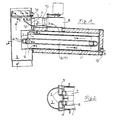
- the heat exchanger 1 connects to the combustion gas discharge duct 3 with side 2.
- the supply and discharge for the circulating water are indicated by 4 and 5, respectively.
- Side 2 of the heat exchanger 1 does not extend, or extends only partly, into the duct 3, so that a large part of this duct 3 remains unobstructed.
- the ducts in the heat exchanger through which the water flows from supply 4 to discharge 5 are indicated by 6 and 7.
- Combustion gases are drawn from the combustion gas discharge duct into the heat exchanger 1 by the fan 8 via the inflow opening 9. These gases flow through the heat exchanger 1 to the fan 8, as indicated by arrows b. From the fan the gases are led into the combustion gas discharge duct 3 via connection 10, passage 11 and a guide baffle 12.
- the performance curve of the fan is as much as possible steep and in terms of maximum pressure and gas displacement volume it is adapted to the capacity of the heating apparatus.
- a steep performance curve is desirable to avoid that the operation of the heating apparatus becomes dependent to an impermissible extent on incidental circumstances, such as downdrafts or obstructions in the combustion gas discharge duct, for instance due to fouling.
- the guide baffle 12 is placed at an angle, so that the combustion gases are led obliquely upwards into the combustion gas discharge duct 3, in the direction of discharge through the duct 3. Due to the inclined position of the guide baffle 12, the combustion gases are led into the combustion gas discharge duct at an angle, strike the wall of the duct, and subsequently deflect in the direction of discharge of the combustion gases from the duct 3. Part of the gases is led into the combustion gas discharge duct 3 at an angle of 90° relative to the central axis of the duct; this is indicated by arrows d.
- a combustion gas shield is obtained in the combustion gas discharge duct 3 in the prolongation of the guide baffle 12, viewed in the direction of flow of the gases from the opening 11 in the duct, which shield extends across virtually the entire cross section of the duct.
- This gas shield prevents the combustion gases that do not flow via the heat exchanger from passing through the discharge duct. Thus it is achieved that virtually all the combustion gas is led through the heat exchanger.
- the combustion gases will be discharged via the combustion gas discharge duct 3, as indicated by arrows c, as the free opening in the duct at the place of the heat exchanger is sufficiently large.
- the combustion gases will be discharged, in part according to arrows b and in part according to arrows c.
- baffle 12 The angle of baffle 12 to the central axis of the duct 3 is between 40° and 70°, preferably between 50° and 60°. Baffle 12 extends partly into the combustion gas discharge duct. The horizontal projection of this baffle 12 is equal to 0.25 to 0.50 times the inner diameter of the combustion gas discharge duct 3. The dimensions of the opening 11 and the fan are such that the combustion gases from the heat exchanger flow into the combustion gas discharge duct with a velocity of between 8 and 12 m/s.
- the condensate formed in the heat exchanger 1 is continuously discharged via opening 13, and that formed in the combustion gas discharge duct 3 via opening 14. Both discharges, 13 and 14, may connect to a joint discharge line via a water lock.
- the fan is located after the heat exchanger, viewed in the direction of flow of the combustion gases. It is also possible to place the fan before the heat exchanger with application of the present invention.
Landscapes
- Engineering & Computer Science (AREA)
- Mechanical Engineering (AREA)
- General Engineering & Computer Science (AREA)
- Combustion & Propulsion (AREA)
- Thermal Sciences (AREA)
- Chemical & Material Sciences (AREA)
- Physics & Mathematics (AREA)
- Instantaneous Water Boilers, Portable Hot-Water Supply Apparatuses, And Control Of Portable Hot-Water Supply Apparatuses (AREA)
- Heating, Cooling, Or Curing Plastics Or The Like In General (AREA)
- Yarns And Mechanical Finishing Of Yarns Or Ropes (AREA)
- Chimneys And Flues (AREA)
- General Induction Heating (AREA)
- Constitution Of High-Frequency Heating (AREA)
- Buildings Adapted To Withstand Abnormal External Influences (AREA)
Claims (5)
Priority Applications (1)
| Application Number | Priority Date | Filing Date | Title |
|---|---|---|---|
| AT82200038T ATE21762T1 (de) | 1981-01-16 | 1982-01-14 | Anordnung mit waermerueckgewinnung. |
Applications Claiming Priority (2)
| Application Number | Priority Date | Filing Date | Title |
|---|---|---|---|
| NL8100182 | 1981-01-16 | ||
| NL8100182A NL8100182A (nl) | 1981-01-16 | 1981-01-16 | Complementeringsinrichting voor een verwarmingsinstallatie. |
Publications (3)
| Publication Number | Publication Date |
|---|---|
| EP0056670A2 EP0056670A2 (fr) | 1982-07-28 |
| EP0056670A3 EP0056670A3 (en) | 1983-02-09 |
| EP0056670B1 true EP0056670B1 (fr) | 1986-08-27 |
Family
ID=19836872
Family Applications (1)
| Application Number | Title | Priority Date | Filing Date |
|---|---|---|---|
| EP82200038A Expired EP0056670B1 (fr) | 1981-01-16 | 1982-01-14 | Assemblage comprenant un dispositif pour récupération de la chaleur |
Country Status (8)
| Country | Link |
|---|---|
| US (1) | US4450901A (fr) |
| EP (1) | EP0056670B1 (fr) |
| AT (1) | ATE21762T1 (fr) |
| CA (1) | CA1174923A (fr) |
| DE (1) | DE3272785D1 (fr) |
| DK (1) | DK17782A (fr) |
| NL (1) | NL8100182A (fr) |
| NO (1) | NO820127L (fr) |
Families Citing this family (19)
| Publication number | Priority date | Publication date | Assignee | Title |
|---|---|---|---|---|
| IT1183737B (it) * | 1984-02-15 | 1987-10-22 | Silvano Cappi | Abbattitore di fumi per gruppi bruciatore-caldaia a combustibile gassoso o liquido |
| US8459984B2 (en) * | 2005-04-26 | 2013-06-11 | Heartland Technology Partners Llc | Waste heat recovery system |
| US7442035B2 (en) * | 2005-04-26 | 2008-10-28 | Gei Development, Llc | Gas induction bustle for use with a flare or exhaust stack |
| US8801897B2 (en) * | 2007-03-13 | 2014-08-12 | Heartland Technology Partners Llc | Compact wastewater concentrator and contaminant scrubber |
| US8741100B2 (en) | 2007-03-13 | 2014-06-03 | Heartland Technology Partners Llc | Liquid concentrator |
| US8679291B2 (en) * | 2007-03-13 | 2014-03-25 | Heartland Technology Partners Llc | Compact wastewater concentrator using waste heat |
| US20100176042A1 (en) * | 2007-03-13 | 2010-07-15 | Duesel Jr Bernard F | Wastewater Concentrator |
| US10005678B2 (en) | 2007-03-13 | 2018-06-26 | Heartland Technology Partners Llc | Method of cleaning a compact wastewater concentrator |
| US8790496B2 (en) * | 2007-03-13 | 2014-07-29 | Heartland Technology Partners Llc | Compact wastewater concentrator and pollutant scrubber |
| CA2751720C (fr) | 2009-02-12 | 2018-04-10 | Heartland Technology Partners Llc | Concentrateur d'eaux usees compact utilisant la chaleur residuelle |
| US8721771B2 (en) | 2011-01-21 | 2014-05-13 | Heartland Technology Partners Llc | Condensation plume mitigation system for exhaust stacks |
| US9296624B2 (en) | 2011-10-11 | 2016-03-29 | Heartland Technology Partners Llc | Portable compact wastewater concentrator |
| US8808497B2 (en) | 2012-03-23 | 2014-08-19 | Heartland Technology Partners Llc | Fluid evaporator for an open fluid reservoir |
| US8741101B2 (en) | 2012-07-13 | 2014-06-03 | Heartland Technology Partners Llc | Liquid concentrator |
| US8585869B1 (en) | 2013-02-07 | 2013-11-19 | Heartland Technology Partners Llc | Multi-stage wastewater treatment system |
| US9199861B2 (en) | 2013-02-07 | 2015-12-01 | Heartland Technology Partners Llc | Wastewater processing systems for power plants and other industrial sources |
| KR101393380B1 (ko) * | 2014-03-06 | 2014-05-09 | 김정섭 | 배기가스의 폐열을 이용한 난방용 온풍기 |
| US20200376406A1 (en) | 2019-05-31 | 2020-12-03 | Heartland Technology Partners Llc. | Harmful substance removal system and method |
| CN117870016B (zh) * | 2024-03-13 | 2024-06-11 | 梁山恒源热力有限公司 | 基于物联网的供热系统实时监控方法及系统 |
Family Cites Families (16)
| Publication number | Priority date | Publication date | Assignee | Title |
|---|---|---|---|---|
| US1500838A (en) * | 1924-07-08 | Heating attachment for stove or furnace pipes | ||
| US2276400A (en) * | 1942-03-17 | hubbard | ||
| US2077599A (en) * | 1936-11-18 | 1937-04-20 | Nathaniel B Wales | Heating system |
| US2690720A (en) * | 1950-04-24 | 1954-10-05 | Delbert H Henderson | Dehydrating incinerator |
| US3813039A (en) * | 1973-03-26 | 1974-05-28 | G Wells | Heat exchanger |
| US4012191A (en) * | 1975-06-18 | 1977-03-15 | Foster Wheeler Energy Corporation | System for recovering heat from the exhaust gases of a heat generator |
| US4117883A (en) * | 1976-08-30 | 1978-10-03 | Feldmann William F | Heat retriever |
| DE2656544A1 (de) * | 1976-12-14 | 1978-06-15 | Rosenkranz Gustav | Waermeaustauscher |
| US4147303A (en) * | 1977-04-29 | 1979-04-03 | Anthony Talucci | Heat-saving smoke pipe attachment |
| US4185685A (en) * | 1978-01-03 | 1980-01-29 | Giberson Elwood C | Waste heat recovery system and method |
| DE2817450A1 (de) * | 1978-04-21 | 1979-08-16 | Wolfgang Graffius | Radialgeblaese zum einbau in einen schornstein zur beschleunigung der rauchgase |
| GB2025599A (en) * | 1978-05-04 | 1980-01-23 | Long P W | Waste-heat recovery method and apparatus |
| US4194488A (en) * | 1978-09-27 | 1980-03-25 | William W. Weaver | Home heating system |
| US4217877A (en) * | 1978-09-27 | 1980-08-19 | Uhlyarik Emanuel J | Energy-saving forced-air furnace |
| NL7906088A (nl) * | 1979-08-09 | 1981-02-11 | Interpower Bv | Complementeringsinrichting voor een verwarmings- installatie. |
| NL7907138A (nl) * | 1979-09-26 | 1981-03-30 | Neom Bv | Werkwijze en inrichting voor het bedrijven van een c.v.-installatie. |
-
1981
- 1981-01-16 NL NL8100182A patent/NL8100182A/nl not_active Application Discontinuation
-
1982
- 1982-01-12 CA CA000393982A patent/CA1174923A/fr not_active Expired
- 1982-01-14 DE DE8282200038T patent/DE3272785D1/de not_active Expired
- 1982-01-14 EP EP82200038A patent/EP0056670B1/fr not_active Expired
- 1982-01-14 AT AT82200038T patent/ATE21762T1/de not_active IP Right Cessation
- 1982-01-15 DK DK17782A patent/DK17782A/da not_active Application Discontinuation
- 1982-01-15 NO NO820127A patent/NO820127L/no unknown
- 1982-01-18 US US06/340,048 patent/US4450901A/en not_active Expired - Fee Related
Also Published As
| Publication number | Publication date |
|---|---|
| EP0056670A2 (fr) | 1982-07-28 |
| CA1174923A (fr) | 1984-09-25 |
| DE3272785D1 (en) | 1986-10-02 |
| ATE21762T1 (de) | 1986-09-15 |
| NO820127L (no) | 1982-07-19 |
| US4450901A (en) | 1984-05-29 |
| EP0056670A3 (en) | 1983-02-09 |
| DK17782A (da) | 1982-07-17 |
| NL8100182A (nl) | 1982-08-16 |
Similar Documents
| Publication | Publication Date | Title |
|---|---|---|
| EP0056670B1 (fr) | Assemblage comprenant un dispositif pour récupération de la chaleur | |
| US4012191A (en) | System for recovering heat from the exhaust gases of a heat generator | |
| US10890356B2 (en) | Heat exchange device and heat source machine | |
| US3813039A (en) | Heat exchanger | |
| CA2504330A1 (fr) | Dispositif de traitement de gaz d'echappement | |
| CN207648804U (zh) | 一种燃烧器回流烟气中的水蒸气去除装置 | |
| US5394860A (en) | Method of connecting a heat exchanger to a forced air furnace and related valve | |
| US3822991A (en) | Gas-fired furnace | |
| US5361827A (en) | Economizer system for vapor generation apparatus | |
| GB2090959A (en) | Air Preheater | |
| CN112610972B (zh) | 一种在线消除火电厂燃煤锅炉空预器硫酸氢铵堵灰的装置 | |
| CN207751005U (zh) | 一种炉烟再循环耦合烟气余热变能级利用系统 | |
| RU2185569C1 (ru) | Котельная установка | |
| CN115127097A (zh) | 烟气再循环热压机系统 | |
| JP3796031B2 (ja) | ダクト直結型給湯器及び給湯器排気装置 | |
| JPS61500628A (ja) | すす吹き装置 | |
| CN221402999U (zh) | 一种热电厂冷渣机出口收尘装置 | |
| JP3016132U (ja) | 低温腐食防止装置を備えた空気加熱装置 | |
| KR101932992B1 (ko) | 물유입 방지용 배기덕트를 구비한 가스보일러 | |
| JP2005042999A (ja) | 灰溶融設備 | |
| CN222635310U (zh) | 回转式空预器防堵塞系统 | |
| CN223840645U (zh) | 冷凝式燃气热水器 | |
| CN222617208U (zh) | 一种侧向燃烧设备 | |
| EP0024376A1 (fr) | Appareil de chauffage | |
| SE518478C2 (sv) | Tubrörspanna för fasta bränslen med uppdelat luftflöde |
Legal Events
| Date | Code | Title | Description |
|---|---|---|---|
| PUAI | Public reference made under article 153(3) epc to a published international application that has entered the european phase |
Free format text: ORIGINAL CODE: 0009012 |
|
| AK | Designated contracting states |
Designated state(s): AT BE CH DE FR GB IT LU NL SE |
|
| PUAL | Search report despatched |
Free format text: ORIGINAL CODE: 0009013 |
|
| AK | Designated contracting states |
Designated state(s): AT BE CH DE FR GB IT LI LU NL SE |
|
| 17P | Request for examination filed |
Effective date: 19821216 |
|
| GRAA | (expected) grant |
Free format text: ORIGINAL CODE: 0009210 |
|
| AK | Designated contracting states |
Kind code of ref document: B1 Designated state(s): AT BE CH DE FR GB IT LI LU NL SE |
|
| PG25 | Lapsed in a contracting state [announced via postgrant information from national office to epo] |
Ref country code: NL Effective date: 19860827 Ref country code: LI Effective date: 19860827 Ref country code: IT Free format text: LAPSE BECAUSE OF FAILURE TO SUBMIT A TRANSLATION OF THE DESCRIPTION OR TO PAY THE FEE WITHIN THE PRESCRIBED TIME-LIMIT;WARNING: LAPSES OF ITALIAN PATENTS WITH EFFECTIVE DATE BEFORE 2007 MAY HAVE OCCURRED AT ANY TIME BEFORE 2007. THE CORRECT EFFECTIVE DATE MAY BE DIFFERENT FROM THE ONE RECORDED. Effective date: 19860827 Ref country code: FR Free format text: THE PATENT HAS BEEN ANNULLED BY A DECISION OF A NATIONAL AUTHORITY Effective date: 19860827 Ref country code: CH Effective date: 19860827 Ref country code: BE Effective date: 19860827 Ref country code: AT Effective date: 19860827 |
|
| REF | Corresponds to: |
Ref document number: 21762 Country of ref document: AT Date of ref document: 19860915 Kind code of ref document: T |
|
| PG25 | Lapsed in a contracting state [announced via postgrant information from national office to epo] |
Ref country code: SE Effective date: 19860831 |
|
| REF | Corresponds to: |
Ref document number: 3272785 Country of ref document: DE Date of ref document: 19861002 |
|
| REG | Reference to a national code |
Ref country code: CH Ref legal event code: PL |
|
| EN | Fr: translation not filed | ||
| PG25 | Lapsed in a contracting state [announced via postgrant information from national office to epo] |
Ref country code: LU Free format text: LAPSE BECAUSE OF NON-PAYMENT OF DUE FEES Effective date: 19870131 |
|
| NLV1 | Nl: lapsed or annulled due to failure to fulfill the requirements of art. 29p and 29m of the patents act | ||
| PLBE | No opposition filed within time limit |
Free format text: ORIGINAL CODE: 0009261 |
|
| STAA | Information on the status of an ep patent application or granted ep patent |
Free format text: STATUS: NO OPPOSITION FILED WITHIN TIME LIMIT |
|
| 26N | No opposition filed | ||
| GBPC | Gb: european patent ceased through non-payment of renewal fee | ||
| PG25 | Lapsed in a contracting state [announced via postgrant information from national office to epo] |
Ref country code: DE Effective date: 19871001 |
|
| PG25 | Lapsed in a contracting state [announced via postgrant information from national office to epo] |
Ref country code: GB Effective date: 19881121 |