EP0056847A2 - Dispositif pour enlever et remettre une roue de secours logée sous la benne basculante d'un camion - Google Patents
Dispositif pour enlever et remettre une roue de secours logée sous la benne basculante d'un camion Download PDFInfo
- Publication number
- EP0056847A2 EP0056847A2 EP81108963A EP81108963A EP0056847A2 EP 0056847 A2 EP0056847 A2 EP 0056847A2 EP 81108963 A EP81108963 A EP 81108963A EP 81108963 A EP81108963 A EP 81108963A EP 0056847 A2 EP0056847 A2 EP 0056847A2
- Authority
- EP
- European Patent Office
- Prior art keywords
- lever arm
- spare wheel
- vehicle
- rotary bearing
- bridge
- Prior art date
- Legal status (The legal status is an assumption and is not a legal conclusion. Google has not performed a legal analysis and makes no representation as to the accuracy of the status listed.)
- Granted
Links
- 238000010276 construction Methods 0.000 description 2
- 208000027418 Wounds and injury Diseases 0.000 description 1
- 230000006378 damage Effects 0.000 description 1
- 230000008030 elimination Effects 0.000 description 1
- 238000003379 elimination reaction Methods 0.000 description 1
- 230000002349 favourable effect Effects 0.000 description 1
- 208000014674 injury Diseases 0.000 description 1
- 238000003780 insertion Methods 0.000 description 1
- 230000037431 insertion Effects 0.000 description 1
- 239000000725 suspension Substances 0.000 description 1
Images
Classifications
-
- B—PERFORMING OPERATIONS; TRANSPORTING
- B62—LAND VEHICLES FOR TRAVELLING OTHERWISE THAN ON RAILS
- B62D—MOTOR VEHICLES; TRAILERS
- B62D43/00—Spare wheel stowing, holding, or mounting arrangements
- B62D43/02—Spare wheel stowing, holding, or mounting arrangements external to the vehicle body
- B62D43/04—Spare wheel stowing, holding, or mounting arrangements external to the vehicle body attached beneath the vehicle body
- B62D43/045—Spare wheel stowing, holding, or mounting arrangements external to the vehicle body attached beneath the vehicle body the wheel or its cradle being attached to one or more chains or cables for handling
Definitions
- the invention relates to a device for removing and inserting a spare wheel, which is accommodated under tipping trucks in tippers on truck vehicles, essentially consisting of a lever arm which is rotatably mounted on one side of the vehicle and at the other end a rope run for a rope winch provided lifting device.
- an angular lever arm has at one end a pivot pin which can be inserted from above into a sleeve formed on the subframe or chassis of the vehicle, and at its other end a cantilever arm ; this boom is slidably disposed with respect to the lever arm or is pivotably attached to the lever arm.
- the largest dimensions of the device when the boom is retracted or swung in are smaller than the dimensions of the cavity enclosed by the spare wheel. Accordingly, the device can be removed from the subframe / chassis and housed in the interior of the spare wheel; in practice, a plastic bag is used to protect the device.
- the invention is therefore based on the object of eliminating the disadvantages of the known device, in particular thus creating a device which is safer in terms of accident, requires a minimum of operating effort and satisfies the stated regulations.
- the vehicle-side rotary bearing of the one-piece lever arm is attached to the tilting bridge and is arranged such that when the tilting bridge is raised to remove / insert the spare wheel, the axis of rotation of the rotary bearing is at right angles to the vehicle.
- a structure of the invention that is simple in terms of weight, and particularly favorable in tight spaces, is that the vehicle-side pivot bearing is formed from a pivot pin arranged on the tilting bridge and a socket held on the pivot pin, which with the lever arm provides space for one Removing / inserting the spare wheel enlarging angle is connected.
- the socket on the pivot pin can be used for good accessibility when mounting and removing the device on the pivot pin on the pivot bridge side are held in that a respective shoulder of two half-shells detachably connected to the pivot of the pivot bearing engages in a circumferential groove let into the bushing of the pivot bearing from the outside.
- a last embodiment of the invention provides that a rigid support connected to the bushing and to the lever arm is attached below the connection point between the bushing of the rotary bearing and the lever arm, which at the same time a receptacle for a rotatably mounted rope pulley and a lifting device interacting with it, for example forms a manually operated safety ratchet winch, with the support and the lever arm having passage openings for a rope of the lifting device.
- the advantages that can be achieved with the object according to the invention are, in particular, that the device is ready for use after the removal and insertion of the spare wheel accommodated under the tipping bridge, without any dangerous actions for the driving personnel, and is particularly continuously available.
- the arrangement according to the invention of the axis of the rotary bearing when the tilting bridge is raised advantageously results in positions of the lever arm that are free of restoring forces and thus can only be changed intentionally.
- the simple construction, in particular the one-piece design of the lever arm and the associated elimination of the previously known telescopic / pivotable arm make the device cheaper, easier to operate and maintain.
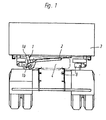
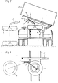
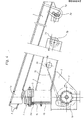
- a spare wheel 4 is located under a tilting bridge 3 in the center of the vehicle on an auxiliary or intermediate space 8 articulated on the chassis.
- a pivot pin la of a rotary bearing 1 is fastened, which is shown in more detail in FIG . 1, 2 and 4, the rotary bearing 1 also has a bushing lb which, on the one hand, engages around the pivot pin la and, on the other hand, is connected to a one-piece lever arm 2 designed as a hollow body.
- the other end of the lever arm 2 is provided with a rope guide 7b for a rope 7c of a lifting device 7, according to FIG. 4 a safety ratchet winch.
- the end of the cable 7c pointing towards the spare wheel 4 can be connected to the spare wheel 4 via hooks 7d located thereon.
- the other end of the rope 7c is guided via a deflection arranged within the lever arm 2, according to FIG. 4 via a bolt 2a welded into the lever arm 2, and via visible through openings in the lever arm 2 and in a support 6 on a rope pulley 7a arranged therein.
- the support 6 lies below the connection point between the bushing lb and the lever arm 2, is welded to these two parts, serves for bracing this connection point and, in addition to the already mentioned mounting of the rope sheave 7a, also for attaching the lifting device 7.
- the bush 1b also has a circumferential groove 1c, into which lugs 5a of two half-shells 5 engage; these half-shells 5 envelop the upper, offset part of the pivot pin la and are connected to it together via a screw connection.
- the hooks 7d are fixed to a suspension 3a attached to the tilting bridge 3.
Landscapes
- Engineering & Computer Science (AREA)
- Chemical & Material Sciences (AREA)
- Combustion & Propulsion (AREA)
- Transportation (AREA)
- Mechanical Engineering (AREA)
- Jib Cranes (AREA)
- Vehicle Cleaning, Maintenance, Repair, Refitting, And Outriggers (AREA)
- Emergency Lowering Means (AREA)
- Lift-Guide Devices, And Elevator Ropes And Cables (AREA)
Priority Applications (1)
| Application Number | Priority Date | Filing Date | Title |
|---|---|---|---|
| AT81108963T ATE14701T1 (de) | 1981-01-23 | 1981-10-27 | Vorrichtung zum entnehmen und einbringen eines bei kippern auf lkw-fahrzeugen unter der kippbruecke untergebrachten reserverades. |
Applications Claiming Priority (2)
| Application Number | Priority Date | Filing Date | Title |
|---|---|---|---|
| DE3102205 | 1981-01-23 | ||
| DE19813102205 DE3102205A1 (de) | 1981-01-23 | 1981-01-23 | Vorrichtung zum entnehmen und einbringen eines bei kippern auf lkw-fahrzeugen unter der kippbruecke untergebrachten reserverades |
Publications (3)
| Publication Number | Publication Date |
|---|---|
| EP0056847A2 true EP0056847A2 (fr) | 1982-08-04 |
| EP0056847A3 EP0056847A3 (en) | 1983-06-15 |
| EP0056847B1 EP0056847B1 (fr) | 1985-08-07 |
Family
ID=6123220
Family Applications (1)
| Application Number | Title | Priority Date | Filing Date |
|---|---|---|---|
| EP81108963A Expired EP0056847B1 (fr) | 1981-01-23 | 1981-10-27 | Dispositif pour enlever et remettre une roue de secours logée sous la benne basculante d'un camion |
Country Status (4)
| Country | Link |
|---|---|
| EP (1) | EP0056847B1 (fr) |
| JP (1) | JPS57140283A (fr) |
| AT (1) | ATE14701T1 (fr) |
| DE (2) | DE3102205A1 (fr) |
Cited By (2)
| Publication number | Priority date | Publication date | Assignee | Title |
|---|---|---|---|---|
| US5519423A (en) * | 1994-07-08 | 1996-05-21 | Hewlett-Packard Company | Tuned entrance fang configuration for ink-jet printers |
| GB2523470A (en) * | 2015-02-06 | 2015-08-26 | Daimler Ag | Mounting device for mounting a spare wheel on a structure of a vehicle |
Families Citing this family (2)
| Publication number | Priority date | Publication date | Assignee | Title |
|---|---|---|---|---|
| DE20008071U1 (de) * | 2000-05-04 | 2001-09-13 | Franz Xaver Meiller Fahrzeug- und Maschinenfabrik - GmbH & Co KG, 80997 München | Fahrzeugaufbau, insbesondere Kippbrückenunterbau, und zugehöriges Bodenblech |
| EP4257461A1 (fr) * | 2022-04-07 | 2023-10-11 | Iveco S.P.A. | Déplacement d'une charge pour un véhicule |
-
1981
- 1981-01-23 DE DE19813102205 patent/DE3102205A1/de not_active Withdrawn
- 1981-10-27 AT AT81108963T patent/ATE14701T1/de not_active IP Right Cessation
- 1981-10-27 DE DE8181108963T patent/DE3171724D1/de not_active Expired
- 1981-10-27 EP EP81108963A patent/EP0056847B1/fr not_active Expired
-
1982
- 1982-01-20 JP JP57006213A patent/JPS57140283A/ja active Pending
Cited By (2)
| Publication number | Priority date | Publication date | Assignee | Title |
|---|---|---|---|---|
| US5519423A (en) * | 1994-07-08 | 1996-05-21 | Hewlett-Packard Company | Tuned entrance fang configuration for ink-jet printers |
| GB2523470A (en) * | 2015-02-06 | 2015-08-26 | Daimler Ag | Mounting device for mounting a spare wheel on a structure of a vehicle |
Also Published As
| Publication number | Publication date |
|---|---|
| ATE14701T1 (de) | 1985-08-15 |
| DE3171724D1 (en) | 1985-09-12 |
| EP0056847A3 (en) | 1983-06-15 |
| EP0056847B1 (fr) | 1985-08-07 |
| JPS57140283A (en) | 1982-08-30 |
| DE3102205A1 (de) | 1982-08-19 |
Similar Documents
| Publication | Publication Date | Title |
|---|---|---|
| DE2821295A1 (de) | Container-ladevorrichtung | |
| EP1396466B1 (fr) | Chariot de manutention avec une ouverture latèrale d' enlèvement de batteries | |
| DE2702403A1 (de) | Scheibenwischer | |
| EP0056847B1 (fr) | Dispositif pour enlever et remettre une roue de secours logée sous la benne basculante d'un camion | |
| DE3030820A1 (de) | Mobilkran mit einem teleskopausleger | |
| DE2850667A1 (de) | Sicherheits-haltevorrichtung fuer einen hebebaum | |
| EP0543276A1 (fr) | Grue mobile | |
| DE102004018644A1 (de) | Telelader, insbesondere Reachstacker | |
| DE3808313C2 (fr) | ||
| DE3106117A1 (de) | "hecktuer fuer panzerfahrzeuge" | |
| DE19840151B4 (de) | Abstützstruktur für Radfahrzeuge | |
| DE8101660U1 (de) | Vorrichtung zum entnehmen und einbringen eines bei kippern auf lkw-fahrzeugen unter der kippbruecke untergebrachten reserverades | |
| DE2944395C2 (de) | Greif- und Ladevorrichtung | |
| DE19721333C1 (de) | Heckportalträgerkombination für Fahrzeuge aller Art mit beweglichem Dach | |
| DE2743373B2 (de) | Elektrokarren mit Ladeplattform und hinter dem Fahrersitz angeordnetem Hydraulikdrehkran | |
| DE3239854C2 (de) | Kranlaufwagen | |
| DE3210013C2 (de) | Mobile oder stationäre Förderkorbbeschickungseinrichtung | |
| DE2750479A1 (de) | Muellwagen | |
| DE3215476A1 (de) | Dachgepaecktraeger fuer kraftfahrzeuge | |
| DE8709071U1 (de) | Hebevorrichtung | |
| DE1229263B (de) | Lastkraftfahrzeug mit Ladekran | |
| DE2922995C2 (de) | Kippvorrichtung zum kippbaren Aufhängen von Transportbehältern an Hubbalken | |
| DE3440280A1 (de) | Vorrichtung zum wechseln der einbaulage eines zugsattelzapfens | |
| DE2322383C3 (de) | Abstützung für einen Mobilkran oder dergleichen Schwerlastfahrzeug | |
| DE1161515B (de) | UEberfahrbruecke |
Legal Events
| Date | Code | Title | Description |
|---|---|---|---|
| PUAI | Public reference made under article 153(3) epc to a published international application that has entered the european phase |
Free format text: ORIGINAL CODE: 0009012 |
|
| 17P | Request for examination filed |
Effective date: 19811027 |
|
| AK | Designated contracting states |
Designated state(s): AT BE CH DE FR GB IT LU NL SE |
|
| PUAL | Search report despatched |
Free format text: ORIGINAL CODE: 0009013 |
|
| AK | Designated contracting states |
Designated state(s): AT BE CH DE FR GB IT LI LU NL SE |
|
| ITF | It: translation for a ep patent filed | ||
| GRAA | (expected) grant |
Free format text: ORIGINAL CODE: 0009210 |
|
| AK | Designated contracting states |
Designated state(s): AT BE CH DE FR GB IT LI LU NL SE |
|
| REF | Corresponds to: |
Ref document number: 14701 Country of ref document: AT Date of ref document: 19850815 Kind code of ref document: T |
|
| REF | Corresponds to: |
Ref document number: 3171724 Country of ref document: DE Date of ref document: 19850912 |
|
| ET | Fr: translation filed | ||
| PGFP | Annual fee paid to national office [announced via postgrant information from national office to epo] |
Ref country code: AT Payment date: 19851030 Year of fee payment: 5 |
|
| PG25 | Lapsed in a contracting state [announced via postgrant information from national office to epo] |
Ref country code: LU Free format text: LAPSE BECAUSE OF NON-PAYMENT OF DUE FEES Effective date: 19851031 |
|
| PGFP | Annual fee paid to national office [announced via postgrant information from national office to epo] |
Ref country code: NL Payment date: 19851031 Year of fee payment: 5 |
|
| PLBE | No opposition filed within time limit |
Free format text: ORIGINAL CODE: 0009261 |
|
| STAA | Information on the status of an ep patent application or granted ep patent |
Free format text: STATUS: NO OPPOSITION FILED WITHIN TIME LIMIT |
|
| 26N | No opposition filed | ||
| PG25 | Lapsed in a contracting state [announced via postgrant information from national office to epo] |
Ref country code: AT Effective date: 19861027 |
|
| PG25 | Lapsed in a contracting state [announced via postgrant information from national office to epo] |
Ref country code: SE Effective date: 19861028 |
|
| PG25 | Lapsed in a contracting state [announced via postgrant information from national office to epo] |
Ref country code: LI Effective date: 19861031 Ref country code: CH Effective date: 19861031 Ref country code: BE Effective date: 19861031 |
|
| BERE | Be: lapsed |
Owner name: RINGFEDER G.M.B.H. Effective date: 19861031 |
|
| PG25 | Lapsed in a contracting state [announced via postgrant information from national office to epo] |
Ref country code: NL Effective date: 19870501 |
|
| NLV4 | Nl: lapsed or anulled due to non-payment of the annual fee | ||
| PG25 | Lapsed in a contracting state [announced via postgrant information from national office to epo] |
Ref country code: FR Free format text: LAPSE BECAUSE OF NON-PAYMENT OF DUE FEES Effective date: 19870630 |
|
| REG | Reference to a national code |
Ref country code: CH Ref legal event code: PL |
|
| GBPC | Gb: european patent ceased through non-payment of renewal fee | ||
| PG25 | Lapsed in a contracting state [announced via postgrant information from national office to epo] |
Ref country code: DE Effective date: 19870701 |
|
| REG | Reference to a national code |
Ref country code: FR Ref legal event code: ST |
|
| PG25 | Lapsed in a contracting state [announced via postgrant information from national office to epo] |
Ref country code: GB Effective date: 19881121 |
|
| EUG | Se: european patent has lapsed |
Ref document number: 81108963.0 Effective date: 19870812 |