EP0056985A2 - Dispositif pour améliorer le découplage des antennes - Google Patents
Dispositif pour améliorer le découplage des antennes Download PDFInfo
- Publication number
- EP0056985A2 EP0056985A2 EP82100408A EP82100408A EP0056985A2 EP 0056985 A2 EP0056985 A2 EP 0056985A2 EP 82100408 A EP82100408 A EP 82100408A EP 82100408 A EP82100408 A EP 82100408A EP 0056985 A2 EP0056985 A2 EP 0056985A2
- Authority
- EP
- European Patent Office
- Prior art keywords
- antennas
- partition
- antenna
- transmitting
- receiving
- Prior art date
- Legal status (The legal status is an assumption and is not a legal conclusion. Google has not performed a legal analysis and makes no representation as to the accuracy of the status listed.)
- Ceased
Links
Images


Classifications
-
- H—ELECTRICITY
- H01—ELECTRIC ELEMENTS
- H01Q—ANTENNAS, i.e. RADIO AERIALS
- H01Q21/00—Antenna arrays or systems
- H01Q21/06—Arrays of individually energised antenna units similarly polarised and spaced apart
-
- H—ELECTRICITY
- H01—ELECTRIC ELEMENTS
- H01Q—ANTENNAS, i.e. RADIO AERIALS
- H01Q1/00—Details of, or arrangements associated with, antennas
- H01Q1/52—Means for reducing coupling between antennas; Means for reducing coupling between an antenna and another structure
- H01Q1/521—Means for reducing coupling between antennas; Means for reducing coupling between an antenna and another structure reducing the coupling between adjacent antennas
- H01Q1/525—Means for reducing coupling between antennas; Means for reducing coupling between an antenna and another structure reducing the coupling between adjacent antennas between emitting and receiving antennas
-
- H—ELECTRICITY
- H01—ELECTRIC ELEMENTS
- H01Q—ANTENNAS, i.e. RADIO AERIALS
- H01Q19/00—Combinations of primary active antenna elements and units with secondary devices, e.g. with quasi-optical devices, for giving the antenna a desired directional characteristic
- H01Q19/10—Combinations of primary active antenna elements and units with secondary devices, e.g. with quasi-optical devices, for giving the antenna a desired directional characteristic using reflecting surfaces
Definitions
- the invention relates to a device for improving the decoupling of helical transmit and / or receive antennas of at least one pair of antennas with opposing circular polarization, which are perpendicular to an electrically conductive plane reflector wall.
- the invention has for its object to significantly improve the decoupling in the case of circular polarization in opposite directions.
- a device which is characterized by at least one electrically conductive, cylindrical partition wall which runs through the middle between the two antennas of a pair of antennas, in particular between a transmitting and a receiving antenna, and is perpendicular to the reflector wall and electrically is conductively connected to this.
- This partition shields, for example, the receiving antenna from the associated transmitting antenna, the decoupling mainly from the height of the partition, measured perpendicular to the reflector wall.
- Preferred embodiments of the device according to the invention are characterized in that the height of the partition essentially corresponds to half the wavelength. With this dimensioning, the greatest possible decoupling occurs with the smallest possible decrease in the antenna gain, that is to say an optimal decoupling, regardless of the antenna spacing and the length of the partition wall measured parallel to the reflector wall.
- a sheet or grating with a smaller mesh size in relation to the wavelength is preferably provided as the partition, which can be easily manufactured and attached.
- the partition is flat and its length measured parallel to the reflector wall corresponds at least to the wavelength.
- the two transmitting antennas on the one hand and the two receiving antennas on the other hand are arranged crosswise and that a flat partition is arranged between two antennas, which meet in the middle of the antenna arrangement and are electrically conductively connected. This creates a simple and therefore easy to manufacture, effective arrangement.
- the four transmitting or receiving antennas occupy the four corners of an outer square; that the four receiving or transmitting antennas occupy the four corners of an inner square that is rotated by 45 ° with respect to the outer square; and that between an outer transmitting or receiving antenna and two inner receiving or transmitting antennas one at a distance from this transmitting or Receiving antenna curved partition is present.
- all of the receiving antennas are shielded from each transmitting antenna in a simple manner.
- the arrangement is such that the connecting line of the partition T coincides with the shorter center line of the rectangle of the reflector wall R and that the trace of the plane determined by the longitudinal axes of the two antennas S and E runs along the longer center line of the rectangle of the reflector wall R.
- the height h of the partition T measured perpendicular to the reflector wall should correspond to the mean half operating wavelength ⁇ of the electromagnetic waves emitted by the transmitting antenna S and received by the receiving antenna E.
- the width b of the reflector wall R measured perpendicular to the connection plane of the antennas S and E should correspond to ⁇ .
- the antenna spacing a is also ⁇ .
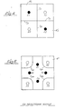
- the second embodiment according to FIG. 2 is for decoupling four helical transmit and receive antennas S1 and S2 or E1 and E2 two pairs of antennas with circular polarization in opposite directions, which are perpendicular to an electrically conductive, flat, square reflector wall R 'made of sheet metal, determined and suitable.
- the reflector wall R ' consists of two coherent, rectangular halves R' 1 and R ' 2 , on the connecting line of which two butt-jointed partition walls T 12 and T 21 are located, which are electrically conductively connected both to one another and to the reflector wall R'.
- the plane of the two partition walls T 12 and T 21 runs in the middle between the transmitting antenna S1 and the receiving antenna E2 on the one hand and the transmitting antenna S2 and the receiving antenna E1 on the other hand, the two antennas E and S of each pair of antennas 1 and 2 passing through a partition wall T 11 and T 22 are shielded against each other, which also butt along the abutting line of the partitions T 12 and T 21 .
- the partitions T 11 , T 12 , T 21 and T 22 consist of flat metal sheets.
- the antenna arrangement is such that the four antennas occupy the four corners of a rectangle and antennas of the same name diagonally opposite. There is therefore a doubling of the first embodiment with one antenna pair being turned with respect to the other.
- the third embodiment according to FIG. 5 is for decoupling eight helical transmit and receive antennas S1, S2, S3 and S4 or E1, E2, E3 and E4 from four antenna pairs with circular polarization in opposite directions, which are on an electrically conductive, flat, square reflector wall R "made of sheet metal are vertical, determined and suitable.
- the antenna arrangement here is such that the four transmitting antennas S occupy the four corners of a larger square and stand on the diagonals of the reflector wall R" and that the four receiving antennas E the four corners of one occupy smaller squares and stand on the center lines of the reflector wall R ", the antenna E1 being close to the connection plane of the antennas S1 and S2.
- the device for improving the decoupling of these symmetrically Ichen antenna arrangement is itself symmetrical and consists of four identical cylindrical partition walls T made of sheet metal, which are each bent concentrically around a transmitting antenna S, with a partition wall T 122 through the middle between the antenna S2 on the one hand and the antenna E1 or E2 on the other Partition T 233 through the centers between the antenna S3 on the one hand and the antenna E2 or E3 on the other, a partition T 344 through the centers between the antenna S4 on the one hand and the antenna E3 or E4 on the other hand and a partition T 411 through the centers between the Antenna S1 on the one hand and antenna E4 or E1 on the other hand.
- the partition walls T122. T 233 ' T 344 and T 411 are perpendicular to the reflector wall R
Landscapes
- Aerials With Secondary Devices (AREA)
- Variable-Direction Aerials And Aerial Arrays (AREA)
Applications Claiming Priority (2)
| Application Number | Priority Date | Filing Date | Title |
|---|---|---|---|
| DE3102323A DE3102323C2 (de) | 1981-01-24 | 1981-01-24 | Wendelantennengruppe |
| DE3102323 | 1981-01-24 |
Publications (2)
| Publication Number | Publication Date |
|---|---|
| EP0056985A2 true EP0056985A2 (fr) | 1982-08-04 |
| EP0056985A3 EP0056985A3 (fr) | 1982-09-29 |
Family
ID=6123279
Family Applications (1)
| Application Number | Title | Priority Date | Filing Date |
|---|---|---|---|
| EP82100408A Ceased EP0056985A3 (fr) | 1981-01-24 | 1982-01-21 | Dispositif pour améliorer le découplage des antennes |
Country Status (3)
| Country | Link |
|---|---|
| US (1) | US4460899A (fr) |
| EP (1) | EP0056985A3 (fr) |
| DE (1) | DE3102323C2 (fr) |
Cited By (4)
| Publication number | Priority date | Publication date | Assignee | Title |
|---|---|---|---|---|
| EP0186455A3 (fr) * | 1984-12-20 | 1987-11-25 | The Marconi Company Limited | Réseau de dipôles |
| EP1829160A4 (fr) * | 2004-12-21 | 2008-08-13 | Korea Electronics Telecomm | Antenne a ultra-isolation |
| WO2017219480A1 (fr) * | 2016-06-22 | 2017-12-28 | 中兴通讯股份有限公司 | Dispositif de découplage |
| EP4106106A1 (fr) * | 2021-06-17 | 2022-12-21 | Rosenberger Hochfrequenztechnik GmbH & Co. KG | Agencement d'antenne, agencement d'émetteur-récepteur et système de communication |
Families Citing this family (27)
| Publication number | Priority date | Publication date | Assignee | Title |
|---|---|---|---|---|
| US5231407A (en) * | 1989-04-18 | 1993-07-27 | Novatel Communications, Ltd. | Duplexing antenna for portable radio transceiver |
| US5258771A (en) * | 1990-05-14 | 1993-11-02 | General Electric Co. | Interleaved helix arrays |
| US5345248A (en) * | 1992-07-22 | 1994-09-06 | Space Systems/Loral, Inc. | Staggered helical array antenna |
| US5826201A (en) * | 1992-11-25 | 1998-10-20 | Asterion, Inc. | Antenna microwave shield for cellular telephone |
| KR100269584B1 (ko) * | 1998-07-06 | 2000-10-16 | 구관영 | 쵸크 반사기를 갖는 저 사이드로브 이중 편파 지향성 안테나 |
| FI990395A7 (fi) * | 1999-02-24 | 2000-08-25 | Nokia Networks Oy | Laitteisto antennien keskinäisten häiriöiden vaimentamiseksi |
| EP1118137A1 (fr) * | 1999-08-03 | 2001-07-25 | Koninklijke Philips Electronics N.V. | Antenne double et dispositif radioelectrique associe |
| FR2810163A1 (fr) * | 2000-06-09 | 2001-12-14 | Thomson Multimedia Sa | Perfectionnement aux antennes-sources d'emission/reception d'ondes electromagnetiques |
| JP2002026629A (ja) * | 2000-07-05 | 2002-01-25 | Anten Corp | 45度偏波ダイバーシティアンテナ |
| SE516842C2 (sv) * | 2000-07-10 | 2002-03-12 | Allgon Ab | Antennanordning för en bärbar radiokommunikationsanordning |
| FI118404B (fi) * | 2001-11-27 | 2007-10-31 | Pulse Finland Oy | Kaksoisantenni ja radiolaite |
| GB2390225A (en) * | 2002-06-28 | 2003-12-31 | Picochip Designs Ltd | Radio transceiver antenna arrangement |
| US8104165B1 (en) | 2004-03-02 | 2012-01-31 | Motion Computing Inc. | Method of forming an apparatus used for reducing electromagnetic interference |
| US7164933B1 (en) | 2004-03-02 | 2007-01-16 | Motion Computing, Inc. | Apparatus and method for reducing the electromagnetic interference between two or more antennas coupled to a wireless communication device |
| US7525502B2 (en) * | 2004-08-20 | 2009-04-28 | Nokia Corporation | Isolation between antennas using floating parasitic elements |
| US7330156B2 (en) * | 2004-08-20 | 2008-02-12 | Nokia Corporation | Antenna isolation using grounded microwave elements |
| KR101553722B1 (ko) * | 2007-06-22 | 2015-09-16 | 노키아 코포레이션 | 안테나 장치 |
| CN102856631B (zh) | 2011-06-28 | 2015-04-22 | 财团法人工业技术研究院 | 天线与其通信装置 |
| TWI511378B (zh) | 2012-04-03 | 2015-12-01 | Ind Tech Res Inst | 多頻多天線系統及其通訊裝置 |
| TWI593167B (zh) | 2015-12-08 | 2017-07-21 | 財團法人工業技術研究院 | 天線陣列 |
| CN107181063A (zh) * | 2016-03-11 | 2017-09-19 | 华为技术有限公司 | 一种天线系统和通信设备 |
| TWI632736B (zh) | 2016-12-27 | 2018-08-11 | 財團法人工業技術研究院 | 多天線通訊裝置 |
| TWI656696B (zh) | 2017-12-08 | 2019-04-11 | 財團法人工業技術研究院 | 多頻多天線陣列 |
| US11276942B2 (en) | 2019-12-27 | 2022-03-15 | Industrial Technology Research Institute | Highly-integrated multi-antenna array |
| US11664595B1 (en) | 2021-12-15 | 2023-05-30 | Industrial Technology Research Institute | Integrated wideband antenna |
| US11862868B2 (en) | 2021-12-20 | 2024-01-02 | Industrial Technology Research Institute | Multi-feed antenna |
| US12489204B2 (en) | 2023-12-26 | 2025-12-02 | Industrial Technology Research Institute | Integrated multi-feed antenna |
Family Cites Families (10)
| Publication number | Priority date | Publication date | Assignee | Title |
|---|---|---|---|---|
| US2441615A (en) * | 1945-01-17 | 1948-05-18 | Rca Corp | Antenna system |
| US2455403A (en) * | 1945-01-20 | 1948-12-07 | Rca Corp | Antenna |
| US2811624A (en) * | 1954-01-07 | 1957-10-29 | Raytheon Mfg Co | Radiation systems |
| DE1049934B (fr) * | 1956-11-08 | |||
| US3681770A (en) * | 1970-01-14 | 1972-08-01 | Andrew Alford | Isolating antenna elements |
| US3757345A (en) * | 1971-04-08 | 1973-09-04 | Univ Ohio State | Shielded end-fire antenna |
| US3739392A (en) * | 1971-07-29 | 1973-06-12 | Sperry Rand Corp | Base-band radiation and reception system |
| US3932876A (en) * | 1974-08-09 | 1976-01-13 | Rca Corporation | Short end-fire circularly polarized antenna |
| US4242686A (en) * | 1978-04-24 | 1980-12-30 | General Dynamics Corporation, Pomona Division | Three-dimensionally curved, knit wire electromagnetic wave reflector |
| JPS5710504A (en) * | 1980-06-24 | 1982-01-20 | Kokusai Denshin Denwa Co Ltd <Kdd> | Array antenna |
-
1981
- 1981-01-24 DE DE3102323A patent/DE3102323C2/de not_active Expired
-
1982
- 1982-01-21 EP EP82100408A patent/EP0056985A3/fr not_active Ceased
- 1982-01-22 US US06/341,857 patent/US4460899A/en not_active Expired - Fee Related
Cited By (5)
| Publication number | Priority date | Publication date | Assignee | Title |
|---|---|---|---|---|
| EP0186455A3 (fr) * | 1984-12-20 | 1987-11-25 | The Marconi Company Limited | Réseau de dipôles |
| EP1829160A4 (fr) * | 2004-12-21 | 2008-08-13 | Korea Electronics Telecomm | Antenne a ultra-isolation |
| US7868837B2 (en) | 2004-12-21 | 2011-01-11 | Electronics And Telecommunications Research Institute | Ultra isolation antenna |
| WO2017219480A1 (fr) * | 2016-06-22 | 2017-12-28 | 中兴通讯股份有限公司 | Dispositif de découplage |
| EP4106106A1 (fr) * | 2021-06-17 | 2022-12-21 | Rosenberger Hochfrequenztechnik GmbH & Co. KG | Agencement d'antenne, agencement d'émetteur-récepteur et système de communication |
Also Published As
| Publication number | Publication date |
|---|---|
| EP0056985A3 (fr) | 1982-09-29 |
| US4460899A (en) | 1984-07-17 |
| DE3102323C2 (de) | 1984-06-07 |
| DE3102323A1 (de) | 1982-08-12 |
Similar Documents
| Publication | Publication Date | Title |
|---|---|---|
| EP0056985A2 (fr) | Dispositif pour améliorer le découplage des antennes | |
| DE69604583T2 (de) | Gedruckte mehrband-monopolantenne | |
| DE4219932C2 (de) | Abschirmungseinrichtung für gedruckte Schaltungskarten | |
| DE69617947T2 (de) | Gedruckte mehrband monopolantenne | |
| EP0841715A2 (fr) | Antenne plate | |
| DE2538614B2 (de) | Dielektrischer Resonator | |
| EP3220480A1 (fr) | Agencement de rayonnement dipolaire | |
| DE2362913B2 (de) | Spiralantenne | |
| DE19830791C2 (de) | Mit elektromagnetischen Wellen arbeitendes Radargerät | |
| DE2316842B2 (de) | Mehrfrequenzantenne für drei Frequenzbänder | |
| DE3217437A1 (de) | Mikrowellen-richtantenne aus einer dielektrischen leitung | |
| DE69015608T2 (de) | Geschlitzter Hohlleiterstrahler mit quer verlaufenden Schlitzen, die von gedruckten, leitenden Mustern erregt werden. | |
| DE19600516A1 (de) | Antenne | |
| DE3700886A1 (de) | Hohlleiterschlitzantenne fuer doppler-navigatoren | |
| DE2736758C2 (de) | Hornantenne mit Richtcharakteristik für zirkularpolarisierte Wellen | |
| DE2921856C2 (de) | Richtantenne aus zwei eine strahlende Doppelleitung bildenden Streifenleitern und Gruppenantenne unter Verwendung mehrerer derartiger Richtantennen | |
| DE3622175C2 (fr) | ||
| DE2124710A1 (de) | Sende/Empfangs-Antennensystem mit einer Kompensationseinrichtung | |
| DE3638461A1 (de) | Antennensystem fuer mehrfachausnutzung des spektrums durch orthogonale polarisationen | |
| DE102012000762A1 (de) | Antennenabdeckung | |
| DE19961237A1 (de) | Antenne zur Abstrahlung und zum Empfang elektromagnetischer Wellen | |
| DE10311040A1 (de) | Antennenanordnung | |
| EP0989627B1 (fr) | Antenne à double fréquence | |
| DE2603055C3 (de) | Erregersystem für Reflektorantennen | |
| DE2929343C1 (de) | Richtantenne |
Legal Events
| Date | Code | Title | Description |
|---|---|---|---|
| PUAI | Public reference made under article 153(3) epc to a published international application that has entered the european phase |
Free format text: ORIGINAL CODE: 0009012 |
|
| PUAL | Search report despatched |
Free format text: ORIGINAL CODE: 0009013 |
|
| AK | Designated contracting states |
Designated state(s): AT BE CH DE FR GB IT LI LU NL SE |
|
| AK | Designated contracting states |
Designated state(s): AT BE CH DE FR GB IT LI LU NL SE |
|
| RHK1 | Main classification (correction) |
Ipc: H01Q 1/52 |
|
| 17P | Request for examination filed |
Effective date: 19830217 |
|
| STAA | Information on the status of an ep patent application or granted ep patent |
Free format text: STATUS: THE APPLICATION HAS BEEN REFUSED |
|
| 18R | Application refused |
Effective date: 19850831 |
|
| RIN1 | Information on inventor provided before grant (corrected) |
Inventor name: KULKA, SIEGFRIED, DIPL.-ING. Inventor name: SCHMIDT, PETER, DIPL.-ING. |