EP0841715A2 - Antenne plate - Google Patents
Antenne plate Download PDFInfo
- Publication number
- EP0841715A2 EP0841715A2 EP97118934A EP97118934A EP0841715A2 EP 0841715 A2 EP0841715 A2 EP 0841715A2 EP 97118934 A EP97118934 A EP 97118934A EP 97118934 A EP97118934 A EP 97118934A EP 0841715 A2 EP0841715 A2 EP 0841715A2
- Authority
- EP
- European Patent Office
- Prior art keywords
- partial
- short
- antenna
- area
- segment
- Prior art date
- Legal status (The legal status is an assumption and is not a legal conclusion. Google has not performed a legal analysis and makes no representation as to the accuracy of the status listed.)
- Granted
Links
- 239000004020 conductor Substances 0.000 claims abstract description 16
- 230000005855 radiation Effects 0.000 abstract description 16
- 238000012986 modification Methods 0.000 abstract description 2
- 230000004048 modification Effects 0.000 abstract description 2
- 239000002184 metal Substances 0.000 description 8
- 230000006978 adaptation Effects 0.000 description 3
- 238000013461 design Methods 0.000 description 3
- 238000010276 construction Methods 0.000 description 2
- 230000002349 favourable effect Effects 0.000 description 2
- 238000009434 installation Methods 0.000 description 2
- 239000000463 material Substances 0.000 description 2
- 238000012937 correction Methods 0.000 description 1
- 230000006735 deficit Effects 0.000 description 1
- 239000003989 dielectric material Substances 0.000 description 1
- 238000002474 experimental method Methods 0.000 description 1
- 230000001771 impaired effect Effects 0.000 description 1
- 238000011835 investigation Methods 0.000 description 1
- 230000005404 monopole Effects 0.000 description 1
Images

Classifications
-
- H—ELECTRICITY
- H01—ELECTRIC ELEMENTS
- H01Q—ANTENNAS, i.e. RADIO AERIALS
- H01Q21/00—Antenna arrays or systems
- H01Q21/30—Combinations of separate antenna units operating in different wavebands and connected to a common feeder system
-
- H—ELECTRICITY
- H01—ELECTRIC ELEMENTS
- H01Q—ANTENNAS, i.e. RADIO AERIALS
- H01Q1/00—Details of, or arrangements associated with, antennas
- H01Q1/27—Adaptation for use in or on movable bodies
- H01Q1/32—Adaptation for use in or on road or rail vehicles
- H01Q1/325—Adaptation for use in or on road or rail vehicles characterised by the location of the antenna on the vehicle
- H01Q1/3291—Adaptation for use in or on road or rail vehicles characterised by the location of the antenna on the vehicle mounted in or on other locations inside the vehicle or vehicle body
-
- H—ELECTRICITY
- H01—ELECTRIC ELEMENTS
- H01Q—ANTENNAS, i.e. RADIO AERIALS
- H01Q5/00—Arrangements for simultaneous operation of antennas on two or more different wavebands, e.g. dual-band or multi-band arrangements
- H01Q5/30—Arrangements for providing operation on different wavebands
- H01Q5/378—Combination of fed elements with parasitic elements
-
- H—ELECTRICITY
- H01—ELECTRIC ELEMENTS
- H01Q—ANTENNAS, i.e. RADIO AERIALS
- H01Q5/00—Arrangements for simultaneous operation of antennas on two or more different wavebands, e.g. dual-band or multi-band arrangements
- H01Q5/40—Imbricated or interleaved structures; Combined or electromagnetically coupled arrangements, e.g. comprising two or more non-connected fed radiating elements
-
- H—ELECTRICITY
- H01—ELECTRIC ELEMENTS
- H01Q—ANTENNAS, i.e. RADIO AERIALS
- H01Q9/00—Electrically-short antennas having dimensions not more than twice the operating wavelength and consisting of conductive active radiating elements
- H01Q9/04—Resonant antennas
- H01Q9/0407—Substantially flat resonant element parallel to ground plane, e.g. patch antenna
- H01Q9/0421—Substantially flat resonant element parallel to ground plane, e.g. patch antenna with a shorting wall or a shorting pin at one end of the element
Definitions
- the invention relates to flat antennas for terrestrially radiated Signals and for radio connections with frequencies in the GHz range, especially for mobile radio in the 900 MHz and 1.8 GHz bands, with the generic features specified in the preamble of the main claim.
- the invention is based on an operating principle that i.a. in the German patent application No. 195 04 577 based on typical solutions of the prior art was characterized: Two plane-parallel surface elements made of electrical conductive material caused by a side short circuit are connected and one of which (the "ground reference surface") to the outer conductor and the other (the "surface segment" with the function-defining contours and dimensions) on the inner conductor a feeding coaxial cable is connected to form Operation quasi a cavity resonator. On the open side areas in the event of a resonance, a field builds up that becomes a radial radiation in usable orders of magnitude.
- the ground reference area is sufficiently larger than the area segment connected to the inner conductor, or if it is positioned directly over a larger conductive area, a radiation characteristic similar to that of a monopole is obtained.
- the essentially function-determining dimension of the surface segment connected to the inner conductor, the distance from the side with the short-circuit connection to the opposite surface edge, is usually based on the dimension of a quarter of the wavelength corresponding to the middle operating frequency range.
- the antenna principle described here has one disadvantage: It requires approximately symmetrical relationships in the assignment of the two flat components, i.e. as centric as possible Arrangement of the surface segment above the ground reference surface. Leading problems with the positioning of such antennas e.g. on Vehicle bodies for which they are due to the flat design are predestined in themselves. If the flat antenna is not as additional external and add-on part - e.g. on the metallic roof or a hood - is "tolerated", then offers itself best still the installation inside the vehicle below the front or the rear window. For this, the disc should be inclined as flat as possible be.
- An arrangement e.g.
- the invention is therefore based on the object of measures for Influencing the operating parameters of flat antennas in the Developing the generic term of the main claim specified genus, so that the antennas better match the specifics of different Installation positions can be adjusted and the flexibility in the application of the principle is expanded.
- the invention succeeds in influencing the radiation characteristics of the flat antenna and thereby ensuring the typical all-round radiation even under conditions of use that are initially unfavorable for the principle.
- the means according to the invention ensure that, regardless of all modifications to antennas of the construction described here, good adaptation and good profit can always be achieved.
- the variation of the radiation characteristic is made possible by the division of the surface segment in connection with the second short-circuit connection.
- the division into two approximately equal halves while maintaining the overall dimension ⁇ / 4 has proven to be a favorable starting position in experiments; With minor changes in the division ratio and the width of the gap or the degree of overlap of the partial areas, additional corrections are then possible.
- the short, ribbon-like line pieces on both sides of the partial area galvanically connected to the inner conductor of the antenna cable are used to adjust or correct the impedance at the feed point.
- the dimensioning is done experimentally.
- the dimensions are also determined from the distance to the edge of the calotte in the case of a spherical design of the mass reference surface.
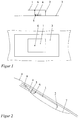
- Figure 2 shows an embodiment according to the German application No. 196 14 068 mentioned above.
- the cap is conductively connected to the mass 8 on one side, for example to the metallic roof edge above the motor vehicle rear window 9.
- the dimensions of the spherical cap are reduced to a quarter of the dimensions of the ground reference surface 3 according to FIG. 1, and apart from the level differences mentioned in the longitudinal axis of the vehicle, no impairments of the antenna parameters can be found compared to the antenna according to FIG.
- the new antenna consists of two sub-areas 10 and 11, each of which is connected to the ground reference area 3 via a separate web 12, 13 - as short-circuit connections.
- the width of the gap 14 in the variant in FIGS. 3a and b is selected such that the gap is not recognized as such by the field corresponding to the operating frequency and that there is a continuous area for this field.
- the same result is achieved by overlapping the partial areas 10, 11, which is shown in FIG. 3c.
- the antenna parameters can be influenced further by varying the width of the gap 14 and the dimensions A and B of the overlap and, moreover, the relative dielectric constant of the dielectric in the overlap region.
- the sections 15 attached to the partial surface 11 serve, by varying the dimensions C and D, for precise adaptation to the cable impedance.
- FIG. 4 again takes up the subject of flat antennas with reduced dimensions of the ground reference area in combination with an antenna for another frequency range.
- a flat antenna according to the invention for radio operation for example in the 900 MHz range, is combined with an antenna 16 for satellite-based vehicle navigation (GPS).
- GPS satellite-based vehicle navigation
- the web 12 forming the short-circuit connection of the partial surface 10 connects to the partial surface at an extremely obtuse angle, so that the larger ground surface which is favorable for the function of the patch antenna 16 was obtained in a simple manner.
- This arrangement is also suitable for positioning below a cover or a flat construction element made of a dielectric material, whether it is a vehicle window 9 or a roof or hood made of a plastic material.
Landscapes
- Physics & Mathematics (AREA)
- Electromagnetism (AREA)
- Engineering & Computer Science (AREA)
- Remote Sensing (AREA)
- Waveguide Aerials (AREA)
Applications Claiming Priority (2)
| Application Number | Priority Date | Filing Date | Title |
|---|---|---|---|
| DE19646100 | 1996-11-08 | ||
| DE19646100A DE19646100A1 (de) | 1996-11-08 | 1996-11-08 | Flachantenne |
Publications (3)
| Publication Number | Publication Date |
|---|---|
| EP0841715A2 true EP0841715A2 (fr) | 1998-05-13 |
| EP0841715A3 EP0841715A3 (fr) | 2000-04-26 |
| EP0841715B1 EP0841715B1 (fr) | 2005-03-16 |
Family
ID=7811040
Family Applications (1)
| Application Number | Title | Priority Date | Filing Date |
|---|---|---|---|
| EP97118934A Expired - Lifetime EP0841715B1 (fr) | 1996-11-08 | 1997-10-30 | Antenne plate |
Country Status (3)
| Country | Link |
|---|---|
| US (1) | US5929812A (fr) |
| EP (1) | EP0841715B1 (fr) |
| DE (2) | DE19646100A1 (fr) |
Cited By (3)
| Publication number | Priority date | Publication date | Assignee | Title |
|---|---|---|---|---|
| WO2000031825A1 (fr) * | 1998-11-20 | 2000-06-02 | Smarteq Wireless Ab | Dispositif antenne |
| GB2347792A (en) * | 1999-03-10 | 2000-09-13 | Andrew Jesman | Antenna |
| WO2000057511A1 (fr) * | 1999-03-24 | 2000-09-28 | Siemens Aktiengesellschaft | Antenne multibande |
Families Citing this family (26)
| Publication number | Priority date | Publication date | Assignee | Title |
|---|---|---|---|---|
| DE19828122A1 (de) * | 1998-06-25 | 1999-12-30 | Fuba Automotive Gmbh | Antennen aus flächigen Elementen |
| CA2364445A1 (fr) * | 1999-03-05 | 2000-09-14 | Katrin A Flotti Jacobsen | Systeme d'antenne a microbandes pour dispositif ce communication |
| DE19922699C2 (de) * | 1999-05-18 | 2001-05-17 | Hirschmann Electronics Gmbh | Antenne mit wenigstens einem Vertikalstrahler |
| US6211831B1 (en) * | 1999-06-24 | 2001-04-03 | Delphi Technologies, Inc. | Capacitive grounding system for VHF and UHF antennas |
| WO2001028035A1 (fr) | 1999-10-12 | 2001-04-19 | Arc Wireless Solutions, Inc. | Antenne microruban a bande etroite duale compacte |
| SE517564C2 (sv) * | 1999-11-17 | 2002-06-18 | Allgon Ab | Antennanordning för en bärbar radiokommunikationsanordning, bärbar radiokommunikationsanordning med sådan antennanordning och metod för att driva nämnda radiokommunikationsanordning |
| SE516474C2 (sv) | 1999-11-19 | 2002-01-22 | Allgon Ab | Antennanordning och kommunikationsanordning innefattande en sådan antennanordning |
| DE19957865A1 (de) * | 1999-12-01 | 2001-06-07 | Volkswagen Ag | Antennenanordnung für ein Fahrzeug |
| WO2001048858A2 (fr) | 1999-12-14 | 2001-07-05 | Rangestar Wireless, Inc. | Ensemble antenne a large bande a faible taux d'absorption specifique (das) |
| US6518933B2 (en) | 2001-05-30 | 2003-02-11 | Ads Corporation | Low profile antenna |
| GB2392563B (en) * | 2002-08-30 | 2004-11-03 | Motorola Inc | Antenna structures and their use in wireless communication devices |
| DE102006039357B4 (de) * | 2005-09-12 | 2018-06-28 | Heinz Lindenmeier | Antennendiversityanlage zum Funkempfang für Fahrzeuge |
| RU2497246C2 (ru) * | 2006-02-22 | 2013-10-27 | МедиаТек Инк. | Антенное устройство и использующее его мобильное устройство связи |
| US20080055045A1 (en) * | 2006-08-31 | 2008-03-06 | 3M Innovative Properties Company | Rfid tag including a three-dimensional antenna |
| DE102007017478A1 (de) * | 2007-04-13 | 2008-10-16 | Lindenmeier, Heinz, Prof. Dr. Ing. | Empfangsanlage mit einer Schaltungsanordnung zur Unterdrückung von Umschaltstörungen bei Antennendiversity |
| EP2037593A3 (fr) * | 2007-07-10 | 2016-10-12 | Delphi Delco Electronics Europe GmbH | Installation de diversité d'antennes pour la réception radio à bande relativement large dans des véhicules |
| DE102007039914A1 (de) * | 2007-08-01 | 2009-02-05 | Lindenmeier, Heinz, Prof. Dr. Ing. | Antennendiversityanlage mit zwei Antennen für den Funkempfang in Fahrzeugen |
| DE102008003532A1 (de) * | 2007-09-06 | 2009-03-12 | Lindenmeier, Heinz, Prof. Dr. Ing. | Antenne für den Satellitenempfang |
| US20090085750A1 (en) * | 2007-09-27 | 2009-04-02 | 3M Innovative Properties Company | Extended RFID tag |
| US8289163B2 (en) * | 2007-09-27 | 2012-10-16 | 3M Innovative Properties Company | Signal line structure for a radio-frequency identification system |
| US8717244B2 (en) | 2007-10-11 | 2014-05-06 | 3M Innovative Properties Company | RFID tag with a modified dipole antenna |
| US8085203B1 (en) | 2008-04-18 | 2011-12-27 | Aero Antenna Inc. | Ground surrounded non-resonant slot-like patch antenna |
| PT2209221T (pt) * | 2009-01-19 | 2018-12-27 | Fuba Automotive Electronics Gmbh | Sistema de recepção para a soma de sinais de antena em fase |
| DE102009011542A1 (de) * | 2009-03-03 | 2010-09-09 | Heinz Prof. Dr.-Ing. Lindenmeier | Antenne für den Empfang zirkular in einer Drehrichtung der Polarisation ausgestrahlter Satellitenfunksignale |
| DE102009023514A1 (de) * | 2009-05-30 | 2010-12-02 | Heinz Prof. Dr.-Ing. Lindenmeier | Antenne für zirkulare Polarisation mit einer leitenden Grundfläche |
| WO2018101104A1 (fr) * | 2016-11-29 | 2018-06-07 | 株式会社村田製作所 | Dispositif d'antenne |
Family Cites Families (13)
| Publication number | Priority date | Publication date | Assignee | Title |
|---|---|---|---|---|
| JPH0659009B2 (ja) * | 1988-03-10 | 1994-08-03 | 株式会社豊田中央研究所 | 移動体用アンテナ |
| US5121127A (en) * | 1988-09-30 | 1992-06-09 | Sony Corporation | Microstrip antenna |
| JP2537390B2 (ja) * | 1988-12-23 | 1996-09-25 | 原田工業株式会社 | プレ―ンアンテナ |
| US5291210A (en) * | 1988-12-27 | 1994-03-01 | Harada Kogyo Kabushiki Kaisha | Flat-plate antenna with strip line resonator having capacitance for impedance matching the feeder |
| JPH02308604A (ja) * | 1989-05-23 | 1990-12-21 | Harada Ind Co Ltd | 移動通信用平板アンテナ |
| JP2712931B2 (ja) * | 1991-09-30 | 1998-02-16 | 三菱電機株式会社 | アンテナ装置 |
| US5402136A (en) * | 1991-10-04 | 1995-03-28 | Naohisa Goto | Combined capacitive loaded monopole and notch array with slits for multiple resonance and impedance matching pins |
| US5355142A (en) * | 1991-10-15 | 1994-10-11 | Ball Corporation | Microstrip antenna structure suitable for use in mobile radio communications and method for making same |
| WO1994003940A1 (fr) * | 1992-08-07 | 1994-02-17 | Deltec New Zealand Limited | Dipole |
| DE19504577A1 (de) * | 1995-02-11 | 1996-08-14 | Fuba Automotive Gmbh | Flachantenne |
| JPH08250917A (ja) * | 1995-03-09 | 1996-09-27 | Matsushita Electric Ind Co Ltd | 無線機用アンテナ |
| DE59501555D1 (de) * | 1995-04-20 | 1998-04-09 | Fuba Automotive Gmbh | Flachantennen-Anordnung |
| DE29606475U1 (de) * | 1996-04-09 | 1996-06-27 | FUBA Automotive GmbH, 31162 Bad Salzdetfurth | Flachantenne |
-
1996
- 1996-11-08 DE DE19646100A patent/DE19646100A1/de not_active Withdrawn
-
1997
- 1997-10-30 EP EP97118934A patent/EP0841715B1/fr not_active Expired - Lifetime
- 1997-10-30 DE DE59712229T patent/DE59712229D1/de not_active Expired - Lifetime
- 1997-11-07 US US08/966,500 patent/US5929812A/en not_active Expired - Lifetime
Cited By (6)
| Publication number | Priority date | Publication date | Assignee | Title |
|---|---|---|---|---|
| WO2000031825A1 (fr) * | 1998-11-20 | 2000-06-02 | Smarteq Wireless Ab | Dispositif antenne |
| US6222497B1 (en) | 1998-11-20 | 2001-04-24 | Smarteq Wireless Ab | Antenna device |
| DE19983744B4 (de) | 1998-11-20 | 2019-07-18 | Smarteq Wireless Ab | Antennenvorrichtung |
| GB2347792A (en) * | 1999-03-10 | 2000-09-13 | Andrew Jesman | Antenna |
| GB2347792B (en) * | 1999-03-10 | 2001-06-06 | Andrew Jesman | Antenna |
| WO2000057511A1 (fr) * | 1999-03-24 | 2000-09-28 | Siemens Aktiengesellschaft | Antenne multibande |
Also Published As
| Publication number | Publication date |
|---|---|
| EP0841715A3 (fr) | 2000-04-26 |
| DE59712229D1 (de) | 2005-04-21 |
| US5929812A (en) | 1999-07-27 |
| DE19646100A1 (de) | 1998-05-14 |
| EP0841715B1 (fr) | 2005-03-16 |
Similar Documents
| Publication | Publication Date | Title |
|---|---|---|
| EP0841715A2 (fr) | Antenne plate | |
| DE69617947T2 (de) | Gedruckte mehrband monopolantenne | |
| DE69920084T2 (de) | Antennenanordnung und Funkgerät mit einer derartigen Antenne | |
| DE69604583T2 (de) | Gedruckte mehrband-monopolantenne | |
| EP0514380B1 (fr) | Combinaison d'antennes | |
| EP1154518B1 (fr) | Antenne intégrée pour téléphones portables | |
| DE68913180T2 (de) | Antenne mit einer flachen Platte für mobile Kommunikation. | |
| EP1522120B1 (fr) | Antenne bi-bande ou multibande de faible hauteur, en particulier pour vehicules automobiles | |
| DE69317235T2 (de) | Wenig Raum beanspruchende, breitbandige Antenne mit zugehörigem Sendeempfänger | |
| DE10304911B4 (de) | Kombinationsantennenanordnung für mehrere Funkdienste für Fahrzeuge | |
| EP3178129B1 (fr) | Antenne unipolaire à bande large à structure multiple pour deux bandes de fréquence séparées par un espace blanc dans la plage d'ondes décimétriques, destinée à des véhicules | |
| EP1024552A2 (fr) | Antenne pour terminaux de radiocommunication sans fil | |
| EP1616367A1 (fr) | Antenne multifonctionnelle | |
| EP0740361A1 (fr) | Système d'antenne plane | |
| DE10350034A1 (de) | Antennenanordnung insbesondere für Radaranwendungen bei Kraftfahrzeugen | |
| DE19614068A1 (de) | Flachantenne | |
| EP2784874A2 (fr) | Antenne monopôle à large bande pour deux bandes de fréquences séparées par un écart de fréquence dans la plage d'ondes décimétriques pour des véhicules | |
| EP3382795A1 (fr) | Antenne destinée à recevoir des signaux satellites polarisés circulairement pour la navigation par satellite sur un véhicule | |
| EP3159967A1 (fr) | Antenne multibande gnss | |
| EP3474374B1 (fr) | Dispositif d'antenne pour signaux satellites polarisés circulairement sur un véhicule | |
| DE69323761T2 (de) | Antenne in y-form | |
| EP1297590A1 (fr) | Antenne fendue | |
| DE3904676A1 (de) | Fahrzeugantenne in form einer schlitzantenne | |
| DE20311035U1 (de) | Antennenanordnung, insbesondere für Kraftfahrzeuge | |
| EP3430679B1 (fr) | Capot de protection d'antenne pour véhicule |
Legal Events
| Date | Code | Title | Description |
|---|---|---|---|
| PUAI | Public reference made under article 153(3) epc to a published international application that has entered the european phase |
Free format text: ORIGINAL CODE: 0009012 |
|
| AK | Designated contracting states |
Kind code of ref document: A2 Designated state(s): DE ES FR GB IT SE |
|
| PUAL | Search report despatched |
Free format text: ORIGINAL CODE: 0009013 |
|
| RIC1 | Information provided on ipc code assigned before grant |
Free format text: 7H 01Q 9/04 A, 7H 01Q 21/30 B, 7H 01Q 1/32 B, 7H 01Q 5/00 B |
|
| AK | Designated contracting states |
Kind code of ref document: A3 Designated state(s): AT BE CH DE DK ES FI FR GB GR IE IT LI LU MC NL PT SE |
|
| RAP1 | Party data changed (applicant data changed or rights of an application transferred) |
Owner name: FUBA AUTOMOTIVE GMBH & CO. KG |
|
| 17P | Request for examination filed |
Effective date: 20000515 |
|
| AKX | Designation fees paid |
Free format text: DE ES FR GB IT SE |
|
| 17Q | First examination report despatched |
Effective date: 20021206 |
|
| GRAP | Despatch of communication of intention to grant a patent |
Free format text: ORIGINAL CODE: EPIDOSNIGR1 |
|
| GRAS | Grant fee paid |
Free format text: ORIGINAL CODE: EPIDOSNIGR3 |
|
| GRAA | (expected) grant |
Free format text: ORIGINAL CODE: 0009210 |
|
| AK | Designated contracting states |
Kind code of ref document: B1 Designated state(s): DE ES FR GB IT SE |
|
| REG | Reference to a national code |
Ref country code: GB Ref legal event code: FG4D Free format text: NOT ENGLISH |
|
| REF | Corresponds to: |
Ref document number: 59712229 Country of ref document: DE Date of ref document: 20050421 Kind code of ref document: P |
|
| PG25 | Lapsed in a contracting state [announced via postgrant information from national office to epo] |
Ref country code: ES Free format text: LAPSE BECAUSE OF FAILURE TO SUBMIT A TRANSLATION OF THE DESCRIPTION OR TO PAY THE FEE WITHIN THE PRESCRIBED TIME-LIMIT Effective date: 20050627 |
|
| GBT | Gb: translation of ep patent filed (gb section 77(6)(a)/1977) |
Effective date: 20050712 |
|
| PG25 | Lapsed in a contracting state [announced via postgrant information from national office to epo] |
Ref country code: GB Free format text: LAPSE BECAUSE OF NON-PAYMENT OF DUE FEES Effective date: 20051030 |
|
| PLBE | No opposition filed within time limit |
Free format text: ORIGINAL CODE: 0009261 |
|
| STAA | Information on the status of an ep patent application or granted ep patent |
Free format text: STATUS: NO OPPOSITION FILED WITHIN TIME LIMIT |
|
| ET | Fr: translation filed | ||
| 26N | No opposition filed |
Effective date: 20051219 |
|
| GBPC | Gb: european patent ceased through non-payment of renewal fee |
Effective date: 20051030 |
|
| PG25 | Lapsed in a contracting state [announced via postgrant information from national office to epo] |
Ref country code: SE Free format text: LAPSE BECAUSE OF FAILURE TO SUBMIT A TRANSLATION OF THE DESCRIPTION OR TO PAY THE FEE WITHIN THE PRESCRIBED TIME-LIMIT Effective date: 20050616 |
|
| REG | Reference to a national code |
Ref country code: FR Ref legal event code: TP |
|
| REG | Reference to a national code |
Ref country code: DE Ref legal event code: R081 Ref document number: 59712229 Country of ref document: DE Owner name: DELPHI TECHNOLOGIES, INC., TROY, US Free format text: FORMER OWNER: DELPHI DELCO ELECTRONICS EUROPE GMBH, 42119 WUPPERTAL, DE Effective date: 20111006 |
|
| PGFP | Annual fee paid to national office [announced via postgrant information from national office to epo] |
Ref country code: DE Payment date: 20141029 Year of fee payment: 18 Ref country code: FR Payment date: 20141017 Year of fee payment: 18 |
|
| PGFP | Annual fee paid to national office [announced via postgrant information from national office to epo] |
Ref country code: IT Payment date: 20141028 Year of fee payment: 18 |
|
| REG | Reference to a national code |
Ref country code: DE Ref legal event code: R119 Ref document number: 59712229 Country of ref document: DE |
|
| PG25 | Lapsed in a contracting state [announced via postgrant information from national office to epo] |
Ref country code: DE Free format text: LAPSE BECAUSE OF NON-PAYMENT OF DUE FEES Effective date: 20160503 Ref country code: IT Free format text: LAPSE BECAUSE OF NON-PAYMENT OF DUE FEES Effective date: 20151030 |
|
| REG | Reference to a national code |
Ref country code: FR Ref legal event code: ST Effective date: 20160630 |
|
| PG25 | Lapsed in a contracting state [announced via postgrant information from national office to epo] |
Ref country code: FR Free format text: LAPSE BECAUSE OF NON-PAYMENT OF DUE FEES Effective date: 20151102 |