EP0057068B1 - Vorrichtung zur zerstörungsfreien Werkstoffprüfung - Google Patents
Vorrichtung zur zerstörungsfreien Werkstoffprüfung Download PDFInfo
- Publication number
- EP0057068B1 EP0057068B1 EP19820300206 EP82300206A EP0057068B1 EP 0057068 B1 EP0057068 B1 EP 0057068B1 EP 19820300206 EP19820300206 EP 19820300206 EP 82300206 A EP82300206 A EP 82300206A EP 0057068 B1 EP0057068 B1 EP 0057068B1
- Authority
- EP
- European Patent Office
- Prior art keywords
- weld line
- carrier
- rotor
- eddy current
- testing
- Prior art date
- Legal status (The legal status is an assumption and is not a legal conclusion. Google has not performed a legal analysis and makes no representation as to the accuracy of the status listed.)
- Expired
Links
- 238000009659 non-destructive testing Methods 0.000 title claims description 5
- 238000012360 testing method Methods 0.000 claims description 26
- 238000007689 inspection Methods 0.000 claims description 23
- 238000000034 method Methods 0.000 claims description 7
- 239000002184 metal Substances 0.000 claims description 6
- 230000003287 optical effect Effects 0.000 claims description 2
- 239000000523 sample Substances 0.000 description 14
- 230000000712 assembly Effects 0.000 description 4
- 238000000429 assembly Methods 0.000 description 4
- 229910000831 Steel Inorganic materials 0.000 description 3
- 230000004907 flux Effects 0.000 description 3
- 239000010959 steel Substances 0.000 description 3
- 238000003466 welding Methods 0.000 description 3
- 230000002411 adverse Effects 0.000 description 2
- XLYOFNOQVPJJNP-UHFFFAOYSA-N water Substances O XLYOFNOQVPJJNP-UHFFFAOYSA-N 0.000 description 2
- 230000015572 biosynthetic process Effects 0.000 description 1
- 238000001816 cooling Methods 0.000 description 1
- 230000008878 coupling Effects 0.000 description 1
- 238000010168 coupling process Methods 0.000 description 1
- 238000005859 coupling reaction Methods 0.000 description 1
- 230000007547 defect Effects 0.000 description 1
- 230000001627 detrimental effect Effects 0.000 description 1
- 239000012530 fluid Substances 0.000 description 1
- 238000010438 heat treatment Methods 0.000 description 1
- 238000004519 manufacturing process Methods 0.000 description 1
- 239000003973 paint Substances 0.000 description 1
- 238000000926 separation method Methods 0.000 description 1
Images


Classifications
-
- G—PHYSICS
- G01—MEASURING; TESTING
- G01N—INVESTIGATING OR ANALYSING MATERIALS BY DETERMINING THEIR CHEMICAL OR PHYSICAL PROPERTIES
- G01N29/00—Investigating or analysing materials by the use of ultrasonic, sonic or infrasonic waves; Visualisation of the interior of objects by transmitting ultrasonic or sonic waves through the object
- G01N29/22—Details, e.g. general constructional or apparatus details
- G01N29/26—Arrangements for orientation or scanning by relative movement of the head and the sensor
- G01N29/262—Arrangements for orientation or scanning by relative movement of the head and the sensor by electronic orientation or focusing, e.g. with phased arrays
-
- G—PHYSICS
- G01—MEASURING; TESTING
- G01N—INVESTIGATING OR ANALYSING MATERIALS BY DETERMINING THEIR CHEMICAL OR PHYSICAL PROPERTIES
- G01N27/00—Investigating or analysing materials by the use of electric, electrochemical, or magnetic means
- G01N27/72—Investigating or analysing materials by the use of electric, electrochemical, or magnetic means by investigating magnetic variables
- G01N27/82—Investigating or analysing materials by the use of electric, electrochemical, or magnetic means by investigating magnetic variables for investigating the presence of flaws
- G01N27/90—Investigating or analysing materials by the use of electric, electrochemical, or magnetic means by investigating magnetic variables for investigating the presence of flaws using eddy currents
- G01N27/9013—Arrangements for scanning
-
- G—PHYSICS
- G01—MEASURING; TESTING
- G01N—INVESTIGATING OR ANALYSING MATERIALS BY DETERMINING THEIR CHEMICAL OR PHYSICAL PROPERTIES
- G01N2291/00—Indexing codes associated with group G01N29/00
- G01N2291/02—Indexing codes associated with the analysed material
- G01N2291/028—Material parameters
- G01N2291/02854—Length, thickness
Definitions
- This invention relates to non-destructive testing apparatus for testing elongate metal bodies such as steel tubes.
- strip is bent, commonly after heating, in a forming mill into a tubular shape.
- the tubular shaped strip is thereafter joined along the now abutting edges by one of a number of alternative techniques such as electric resistance welding, or burner jet welding for example.
- German Patent Specification DE-A1-2854374 discloses an arrangement of weld line examination of longitudinally welded metal tubes by means solely of ultrasonic means and does not disclose or illustrate any specific form of weld line following.
- German Patent Specification DE-A-1811079 discloses an arrangement for testing for defects in the weld line of a metal pipe by means solely of a flux-leakage electromagnetic system with an integrally linked facility for following the weld as such.
- U.S.A. Patent Specification US-A-3540266 discloses apparatus for tracking a weld line as such by mechanical means whilst supporting weld inspection device over the weld.
- non-destructive testing apparatus for testing a longitudinally welded elongate metal body travelling in the direction of its long axis, the apparatus comprising a plurality of sets of ultrasonic weld line inspection devices mounted on and supported by a rotatable carrier which, in use, is located about the path of travel of the body; an eddy current weld inspection device mounted on said carrier; weld line following means connected to the carrier for detecting and following a datum mark along the body; and traversing means controlled by the weld line following means for moving the carrier and the inspection devices about said path of travel to maintain the carrier in a predetermined angular relationship with the datum mark along the body.
- the apparatus may comprise in combination, an eddy current weld line inspection assembly incorporating said carrier, two sets of ultrasonic weld line inspection devices carried by the eddy current inspection device and located one before and one after the eddy current assembly in the path of the elongate metal body to be tested which ultrasonic devices may be adapted to operate one by means of surface wave techniques and the other by means of shear wave techniqes; and weld line following equipment carried by the eddy current weld line inspection assembly.
- the weld line following equipment may comprise optical weld line following equipment adapted for example to follow a paint line applied to the elongate object at the same time as weld formation, but separated from the weld line around the periphery of the elongate object.
- the ultrasonic weld line inspection devices may comprise probes carried on shoes mounted in gimbal fashion for freedom of movement to accommodate the variation in the surface of the object to be tested and to enable immediate and automatic contact with the surface of the object as the object passes through the apparatus.
- Travel limiting means may be provided so as to provide a reasonably restricted movement of the shoes to avoid the possibility of damage in the event of excessive deviation in the surface for example of the object to be tested.
- the eddy current inspection device may likewise comprise one or more probes carried by a limited travel gimbal carried shoe.
- the ultrasonic weld line inspection device and the eddy current inspection device may be mounted for movement on a hollow stator about the path of the object to be tested.
- the movement may be provided by means of a rotor by which the inspection devices are carried and driven for example by means of a driving belt from an adjacent motor, and may be capable of movement through an arc of up to 180° or even 360° with some arrangements about the path of the object to be tested.
- Each of the devices may be mounted on arc-shaped members detachably secured to the rotor member and which may be capable of easy removal, together with their associated inspection devices.
- the apparatus may include a calibration rig for the ultrasonic devices closely associated therewith, the rig comprising an annular member to which the arc-shaped members carrying the ultrasonic devices may be connected for calibration in relation to standard work-pieces which can be located within the calibration device.
- the apparatus may be mountable on a table capable of vertical movement, and replacement inspection devices of various dimensions may be available so that the apparatus is capable of the testing on an in-line basis elongate objects of varying outer dimensions.
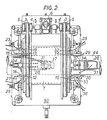
- the apparatus generally comprises a rotor 1 mounted by means of bearings (not shown) for rotation upon an annular stator assembly 2.
- the rotor 1 is arranged to be driven by a pair of belts 3 connected to shafts 4 and pulleys 5 extended from a pneumatic motor 6 alongside the stator.
- the stator carries a saturation coil 7 disposed in annular form for the eddy current testing arrangement.
- each end of the rotor Attached to each end of the rotor are a number of arc segments 8, 9, 10 each having annular grooves. Eddy current and ultrasonic testing devices 11, 12, 13, 14 and 15 respectively, are arranged to be carried in the grooves of appropriate arc members.
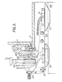
- ultrasonic probe devices 12 and 13 Located on arc members at the leading end of the apparatus are ultrasonic probe devices 12 and 13, one of which is illustrated in detail in Figure 3, together with the eddy current testing device 11 also shown in enlarged form in Figure 3.
- each of these devices comprises a gimbal mounted shoe 16, 17 and 18 respectively, carrying a probe assembly mounted on a floating arm 19, 20 and 21 respectively, which is capable of pivoting movement about an axle such as-22, limited by set screws, 23, 24 and 25 respectively.
- Manifold assemblies 26 and 27 for electrical connection to the various probe assemblies and for fluid connections for coupling purposes to the ultrasonic probe assemblies respectively are mounted also on the rotor at each end.
- the devices at both ends of the apparatus may be adjusted in their arc members by rails 38 and 39 within arc slots 40 and 41 for relative circumferential disposition and for radial location by means of jacking devices 42 and 43 towards or away from the axis of the apparatus.
- the appropriate radial disposition for a steel tube 44 to be tested, and the circumferential disposition for optimum angular alignment about the tube can be arranged.
- One pair of ultrasonic testing devices will be arranged to operate by means of shear wave techniques, the other pair by surface wave techniques.
- the apparatus is designed to enable the rotor, together with its associated eddy current and ultrasonic testing devices to be rotated at least 90° either way from the "top" position which is shown in Figure 1, so that the weld line can be followed over a variation of at least 180° about the periphery of the tube to be tested.
- the eddy current testing probe shoe is of a known pattern having water cooling orifices 45 and testing coils 46 and is arranged to provide a signal indicative of flux variations along the weld line showing the presence of faults.
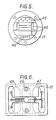
- weld following probe shoe 28 is shown in Figure 6. It has secondary coils 47 and 48 one on each side of the supposed weld line and a primary coil 49 above the supposed line of the weld, provide accurate weld line following in a known manner.
- Calibration of the ultrasonic aspects of the apparatus illustrated can be readily achieved by removing one or more of the arc members carrying the ultrasonic probes from the rotor and placing it on an adjacent annular member (not shown) of identical dimensions to the rotor through which a calibration test piece (not shown) can be passed to check on accurate performance of the ultrasonic probes.
- the apparatus is mounted on a table 50 which can be raised.
- This facility in conjunction with the possibility of varying the separation of the ultrasonic and eddy current devices from the axis of the apparatus, and indeed the possibility of replacing the ultrasonic and eddy devices with others of different dimensions, enables the apparatus to be used in an in-line situation immediately following a welding mill for various diameter tubes with simplicity and speed.
- a welded tube 44 passing through the apparatus is picked up by the testing devices and the weld line following device, the latter causing the rotor with the testing probes to turn on the stator of the apparatus as the weld line varies around the periphery of the tube.
- eddy current testing through the eddy current testing device can be carried out, and simultaneously shear wave and surface wave ultrasonic testing from the ultrasonic probe assemblies, coupled to the tube 44 by water, can be carried out.
Landscapes
- Chemical & Material Sciences (AREA)
- General Health & Medical Sciences (AREA)
- Life Sciences & Earth Sciences (AREA)
- Health & Medical Sciences (AREA)
- Analytical Chemistry (AREA)
- Biochemistry (AREA)
- Physics & Mathematics (AREA)
- General Physics & Mathematics (AREA)
- Immunology (AREA)
- Pathology (AREA)
- Chemical Kinetics & Catalysis (AREA)
- Electrochemistry (AREA)
- Investigating Or Analyzing Materials By The Use Of Ultrasonic Waves (AREA)
- Investigating Or Analyzing Materials By The Use Of Magnetic Means (AREA)
Claims (9)
Applications Claiming Priority (2)
| Application Number | Priority Date | Filing Date | Title |
|---|---|---|---|
| GB8102501 | 1981-01-27 | ||
| GB8102501 | 1981-01-27 |
Publications (2)
| Publication Number | Publication Date |
|---|---|
| EP0057068A1 EP0057068A1 (de) | 1982-08-04 |
| EP0057068B1 true EP0057068B1 (de) | 1985-10-23 |
Family
ID=10519273
Family Applications (1)
| Application Number | Title | Priority Date | Filing Date |
|---|---|---|---|
| EP19820300206 Expired EP0057068B1 (de) | 1981-01-27 | 1982-01-15 | Vorrichtung zur zerstörungsfreien Werkstoffprüfung |
Country Status (4)
| Country | Link |
|---|---|
| EP (1) | EP0057068B1 (de) |
| JP (1) | JPS57139660A (de) |
| DE (1) | DE3266971D1 (de) |
| GB (1) | GB2091890B (de) |
Families Citing this family (4)
| Publication number | Priority date | Publication date | Assignee | Title |
|---|---|---|---|---|
| DE3708454A1 (de) * | 1987-03-16 | 1988-09-29 | Foerster Inst Dr Friedrich | Pruefkopf und verfahren zum fertigen eines solchen pruefkopfes |
| CN114216959B (zh) * | 2021-10-25 | 2024-03-22 | 杭州奔月致远科技有限公司 | 一种链式自适应检测探头架及自适应检测装置 |
| CN114738053B (zh) * | 2022-04-26 | 2023-03-21 | 中铁隧道局集团路桥工程有限公司 | 一种盾构隧道施工用临近管线安全压力检测装置 |
| US12436132B1 (en) | 2023-01-12 | 2025-10-07 | Pitco, Llc | Weld seam finding and marking systems and methods for tubular goods |
Family Cites Families (9)
| Publication number | Priority date | Publication date | Assignee | Title |
|---|---|---|---|---|
| US3540266A (en) * | 1967-10-03 | 1970-11-17 | United States Steel Corp | Positive mechanical weld tracker |
| US3588682A (en) * | 1967-11-28 | 1971-06-28 | Forster F M O | System for inspecting a welded seam with means for generating a signal which is a function of the welding temperature |
| JPS51146885A (en) * | 1975-06-12 | 1976-12-16 | Sumitomo Metal Ind Ltd | Steel material ultrasonic wave and eddy flaw detector |
| JPS5229280A (en) * | 1975-08-30 | 1977-03-04 | Shimadzu Corp | Flaw detecting machine for seam pipes |
| DE2652085A1 (de) * | 1976-11-16 | 1978-05-18 | Hoesch Werke Ag | Vorrichtung zur zerstoerungsfreien werkstoffpruefung |
| GB2015736B (en) * | 1977-12-06 | 1982-04-15 | Babcock & Wilcox Ltd | Automatic inspection of and apparatus for testing of welds |
| JPS5940265B2 (ja) * | 1978-02-13 | 1984-09-28 | 日本鋼管株式会社 | 熱ビレツト渦流探傷装置 |
| JPS54118290A (en) * | 1978-03-06 | 1979-09-13 | Sumitomo Metal Ind | Nonndestructive tester for insideeribbed steel pipe |
| DE2854374A1 (de) * | 1978-12-16 | 1980-06-19 | Ibema Gmbh & Co Kg | Vorrichtung zum zerstoerungsfreien pruefen von schweissnaehten |
-
1982
- 1982-01-15 EP EP19820300206 patent/EP0057068B1/de not_active Expired
- 1982-01-15 DE DE8282300206T patent/DE3266971D1/de not_active Expired
- 1982-01-20 JP JP57006158A patent/JPS57139660A/ja active Pending
- 1982-01-25 GB GB8201990A patent/GB2091890B/en not_active Expired
Also Published As
| Publication number | Publication date |
|---|---|
| JPS57139660A (en) | 1982-08-28 |
| GB2091890B (en) | 1985-04-11 |
| GB2091890A (en) | 1982-08-04 |
| DE3266971D1 (en) | 1985-11-28 |
| EP0057068A1 (de) | 1982-08-04 |
Similar Documents
| Publication | Publication Date | Title |
|---|---|---|
| EP0185761B1 (de) | Wirbelstromprüfeinrichtung mit einer das magnetische feld bestimmenden muffe | |
| CA1297536C (en) | Apparatus for and a method of electromagnetically testing the walls of pipelines | |
| US9291603B2 (en) | Inspection vehicle for the inspection of substantially cylindrical objects | |
| US2563254A (en) | Thickness indicator | |
| US4101832A (en) | Multiprobe eddy current flaw detection device with means to raise and lower the individual probes | |
| EP0210990B1 (de) | Dehnbare wirbelstromsonde | |
| JPH10509236A (ja) | パイプライン移動体 | |
| JPS5940265B2 (ja) | 熱ビレツト渦流探傷装置 | |
| MXPA02003823A (es) | Aparato probador de llantas de alto voltaje. | |
| EP0394591A2 (de) | Drehbarer, mit Rollen versehener Kopf zur Untersuchung mit Hilfe von Wirbelströmen | |
| EP0057068A1 (de) | Vorrichtung zur zerstörungsfreien Werkstoffprüfung | |
| CN114858915A (zh) | 一种移动式保温层内管道无损检测系统及方法 | |
| US5134367A (en) | Rotating eddy current roller head for inspecting and profiling tubing having two separate cross wound coils | |
| CN121253649B (zh) | 一种钛制压力容器焊缝质量自动检测装置 | |
| JP6894452B2 (ja) | タービンロータの検査システム | |
| CN116879386A (zh) | 焊缝检测装置 | |
| US2124578A (en) | Apparatus and method for testing metal articles | |
| CA1240379A (en) | Eddy current flaw detector method and apparatus | |
| KR20020043682A (ko) | 선후행 스트립의 용접점 정밀 가공장치 | |
| JPH0731166B2 (ja) | 超音波探傷装置 | |
| JPS6044162A (ja) | 連鋳設備の鋳片ガイドロ−ルの亀裂測定方法ならびにこれに使用する測定器 | |
| JPH0425650Y2 (de) | ||
| US6596222B2 (en) | Carriage assembly for positioning and moving equipment relative to a wall | |
| CN112730794B (zh) | 一种高铁空心轴无损检测装置 | |
| RU2102737C1 (ru) | Устройство для внутритрубной магнитной дефектоскопии стенок стальных трубопроводов |
Legal Events
| Date | Code | Title | Description |
|---|---|---|---|
| PUAI | Public reference made under article 153(3) epc to a published international application that has entered the european phase |
Free format text: ORIGINAL CODE: 0009012 |
|
| AK | Designated contracting states |
Designated state(s): BE DE FR NL SE |
|
| 17P | Request for examination filed |
Effective date: 19830204 |
|
| GRAA | (expected) grant |
Free format text: ORIGINAL CODE: 0009210 |
|
| AK | Designated contracting states |
Designated state(s): BE DE FR NL SE |
|
| REF | Corresponds to: |
Ref document number: 3266971 Country of ref document: DE Date of ref document: 19851128 |
|
| ET | Fr: translation filed | ||
| PLBE | No opposition filed within time limit |
Free format text: ORIGINAL CODE: 0009261 |
|
| STAA | Information on the status of an ep patent application or granted ep patent |
Free format text: STATUS: NO OPPOSITION FILED WITHIN TIME LIMIT |
|
| 26N | No opposition filed | ||
| PGFP | Annual fee paid to national office [announced via postgrant information from national office to epo] |
Ref country code: NL Payment date: 19890131 Year of fee payment: 10 |
|
| NLS | Nl: assignments of ep-patents |
Owner name: BRITISH STEEL PLC TE LONDEN, GROOT-BRITTANNIE. |
|
| REG | Reference to a national code |
Ref country code: FR Ref legal event code: TP |
|
| PGFP | Annual fee paid to national office [announced via postgrant information from national office to epo] |
Ref country code: FR Payment date: 19891220 Year of fee payment: 9 |
|
| PGFP | Annual fee paid to national office [announced via postgrant information from national office to epo] |
Ref country code: BE Payment date: 19900112 Year of fee payment: 9 |
|
| PGFP | Annual fee paid to national office [announced via postgrant information from national office to epo] |
Ref country code: SE Payment date: 19900116 Year of fee payment: 9 |
|
| PGFP | Annual fee paid to national office [announced via postgrant information from national office to epo] |
Ref country code: DE Payment date: 19900309 Year of fee payment: 9 |
|
| PG25 | Lapsed in a contracting state [announced via postgrant information from national office to epo] |
Ref country code: SE Effective date: 19910116 |
|
| PG25 | Lapsed in a contracting state [announced via postgrant information from national office to epo] |
Ref country code: BE Effective date: 19910131 |
|
| PG25 | Lapsed in a contracting state [announced via postgrant information from national office to epo] |
Ref country code: NL Effective date: 19910801 |
|
| NLV4 | Nl: lapsed or anulled due to non-payment of the annual fee | ||
| PG25 | Lapsed in a contracting state [announced via postgrant information from national office to epo] |
Ref country code: FR Effective date: 19910930 |
|
| PG25 | Lapsed in a contracting state [announced via postgrant information from national office to epo] |
Ref country code: DE Effective date: 19911001 |
|
| REG | Reference to a national code |
Ref country code: FR Ref legal event code: ST |
|
| EUG | Se: european patent has lapsed |
Ref document number: 82300206.8 Effective date: 19910910 |