EP0057089B1 - Méthode et système pour poser des tuyaux dans le sol - Google Patents
Méthode et système pour poser des tuyaux dans le sol Download PDFInfo
- Publication number
- EP0057089B1 EP0057089B1 EP19820300313 EP82300313A EP0057089B1 EP 0057089 B1 EP0057089 B1 EP 0057089B1 EP 19820300313 EP19820300313 EP 19820300313 EP 82300313 A EP82300313 A EP 82300313A EP 0057089 B1 EP0057089 B1 EP 0057089B1
- Authority
- EP
- European Patent Office
- Prior art keywords
- pipe
- vibration
- earth
- leading head
- heading
- Prior art date
- Legal status (The legal status is an assumption and is not a legal conclusion. Google has not performed a legal analysis and makes no representation as to the accuracy of the status listed.)
- Expired
Links
- 238000000034 method Methods 0.000 title claims description 22
- 239000012212 insulator Substances 0.000 claims description 25
- 239000007788 liquid Substances 0.000 claims description 21
- 239000002002 slurry Substances 0.000 claims description 12
- XLYOFNOQVPJJNP-UHFFFAOYSA-N water Substances O XLYOFNOQVPJJNP-UHFFFAOYSA-N 0.000 claims description 9
- 230000005540 biological transmission Effects 0.000 claims description 4
- 239000002689 soil Substances 0.000 description 8
- 239000002245 particle Substances 0.000 description 3
- 238000010586 diagram Methods 0.000 description 2
- 239000000203 mixture Substances 0.000 description 2
- 230000010355 oscillation Effects 0.000 description 2
- 229910000278 bentonite Inorganic materials 0.000 description 1
- 239000000440 bentonite Substances 0.000 description 1
- SVPXDRXYRYOSEX-UHFFFAOYSA-N bentoquatam Chemical compound O.O=[Si]=O.O=[Al]O[Al]=O SVPXDRXYRYOSEX-UHFFFAOYSA-N 0.000 description 1
- 238000010276 construction Methods 0.000 description 1
- 230000008602 contraction Effects 0.000 description 1
- 238000005520 cutting process Methods 0.000 description 1
- 230000003247 decreasing effect Effects 0.000 description 1
- 238000007599 discharging Methods 0.000 description 1
- -1 however Substances 0.000 description 1
Images

Classifications
-
- E—FIXED CONSTRUCTIONS
- E21—EARTH OR ROCK DRILLING; MINING
- E21B—EARTH OR ROCK DRILLING; OBTAINING OIL, GAS, WATER, SOLUBLE OR MELTABLE MATERIALS OR A SLURRY OF MINERALS FROM WELLS
- E21B7/00—Special methods or apparatus for drilling
- E21B7/04—Directional drilling
- E21B7/046—Directional drilling horizontal drilling
-
- E—FIXED CONSTRUCTIONS
- E21—EARTH OR ROCK DRILLING; MINING
- E21B—EARTH OR ROCK DRILLING; OBTAINING OIL, GAS, WATER, SOLUBLE OR MELTABLE MATERIALS OR A SLURRY OF MINERALS FROM WELLS
- E21B7/00—Special methods or apparatus for drilling
- E21B7/24—Drilling using vibrating or oscillating means, e.g. out-of-balance masses
Definitions
- the present invention relates to a method and a system for embedding a pipe under ground, and more particularly to a method and a system for embedding a pipe of relatively small diameter under ground.
- the propelling method includes two types. One is the pressing system in which the rear or backward end of the pipe to be embedded is pressed and propelled while compacting the soil at the forward end of the pipe, and the other is the augering system in which the rear end of the pipe to be embedded is driven while the soil at the forward end of the pipe is augered by rotating an auger mounted in the pipe by a drive unit in a working pit.
- the pressing system which is generally used for a weak ground, requires a strong propelling force, and exerts a great force on the pipe so that the pipe is liable to be damaged. Further, the pipe tends to be displaced from a position to be embedded so that orientation accuracy is relatively low.
- the augering system has the disadvantages that an additional auger is required to be joined each time a succeeding pipe is joined, thereby making operation complicated.
- Examples of such prior art proposals for embedding a pipe underground by propelling the pipe from the near end thereof while forming a hole by pressing or augering or other cutting operations are disclosed in DE-A-1634637 and DE-A1-2701066.
- U.S.-A-3688511 there is disclosed a method of embedding a pipe by connecting a leading head to the pipe to be embedded, and causing pulsating movement of the leading head.
- This patent specification also discloses an apparatus for embedding a pipe, comprising vibration heading means connected to the pipe to be embedded, the vibration heading means having a body connected to the pipe and vibrator means for causing pulsating movement of the body.
- the pulsating movement of the head is caused by directing a jet of a mixture of water and air through a nozzle having alternate contractions and expansions to the exterior of the head, the pulsating jet so caused generating oscillations of the head to facilitate its movement through the ground.
- This apparatus is not suitable for use in accurately embedding a rigid pipe at a depth beneath the surface of the ground due to the irregularity of the oscillations caused by the flush jetting of a mixture of water and air from the head which will affect the accuracy of the orientation of the pipe.
- An object of the present invention is to provide a method and an apparatus by means of which a rigid pipe can be embedded underground whilst being accurately orientated, a relatively small propelling force only being needed to force the pipe through the ground. Because of possibly using small propelling forces the possibility of damage to the pipe during the embedding process is minimised.
- the method of the present invention is particularly characterized in that the pulsating movement of the leading head is a rotational movement of the central axis of the leading head around the longitudinal axis of the pipe, and a propelling force is applied to the backward end of the pipe while the leading head axis is being rotated so as to drive the pipe into the earth, transmission of the pulsating movement of the leading head to the pipe being damped by a vibration insulator forming a connection between the leading head and the pipe thereby substantially to prevent vibration due to the rotational movement of the head axis about the pipe axis from being transmitted to the pipe.
- the vibration of the leading head provided at the forward end of the pipe to be embedded causes vibration of the earth in the vicinity of the forward end of the leading head.
- the arrangement of soil particles of the earth is disturbed so that the soil particles are mobilized thereby to reduce the strength of the earth. In this way, it is possible to easily propel the pipe with a small propelling force.
- the vibration of the leading head is substantially prevented from being transmitting to the pipe to be embedded by the provision of the vibration insulator as the connection between the head and the pipe. This protects the rigid pipe from being subjected to lateral forces which might otherwise damage it.
- the pipe embedding method according to the present invention preferably further comprises the step of discharging from the leading head a liquid for reducing the strength of the earth and converting the earth into slurry.
- Said liquid may be water.
- the apparatus of the present invention is particularly characterized in that said vibrator means comprises a shaft rotatably mounted within said body and carrying an eccentric weight and means for rotating the shaft, drive means is associated with said backward end of the pipe for applying a propelling force to the pipe from the backward end thereof so as to drive the pipe into earth, and vibration insulator means is connected between the vibration heading means and the forward end of the pipe to damp transmission to the pipe of movement of the body caused by rotation of the shaft and eccentric weight.
- the pipe embedding means preferably comprises means for supplying the earth adjacent to the vibration heading means with a liquid for reducing the strength of the earth and converting the earth into slurry.
- Said liquid supply means may include at least one liquid supply port formed in the body of said vibration heading means.
- a system for implementing a method of embedding a pipe under ground is generally designated by reference numeral 2.
- the pipe embedding system 2 comprises a vibration heading unit 8 connected to a forward end 6 of a pipe 4 to be embedded under ground and a drive unit 12 associated with a backward end 10 of the pipe 4 for applying the propelling force to the pipe 4 from the backward end 10 thereby to drive the pipe 4 into earth 14.
- the pipe 4 to be embedded under ground includes three pipe elements 16,18 and 20, and the drive unit 12 includes a hydraulic cyclinder 24 installed within a working pit 22 provided in the earth 14.
- the vibration heading unit 8 preferably includes a body 26 connected to the forward end 6 of the pipe 4 to provide a leading head for the pipe 4, and a vibrator 28 for vibrating the body 26.
- the vibrator 28 includes an eccentric shaft 30 rotatably mounted within the body 26.
- the eccentric shaft 30 includes an eccentric weight 32 and is covered with a casing 34.
- the eccentric shaft 36 is rotated by a motor 36, which is connected through power supply lines 38 to a power source (not shown) arranged in the working pit 22.
- the method and the system for embedding a pipe under ground have the advantages that the propelling force to be applied to the pipe from the backward end thereof is considerably saved, and since a force exerted on the pipe is small, the pipe to be embedded is not likely to be damaged and it is possible to embed a pipe with high accuracy of orientation. Further, no additional operation is required when a succeeding pipe is joined, and therefore it is possible to improve the working efficiency and simplify the construction.
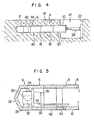
- FIG. 4 An embodiment of the apparatus for carrying out the method of embedding a pipe under ground according to the present invention will be described with reference to Figs. 4 and 5.
- the pipe embedding system shown in the drawings is generally designated by numeral 40, and component elements similar to those shown in Figs. 1 and 2 are denoted by like reference numerals respectively.
- the pipe embedding apparatus 40 further comprises a vibration insulator 42 inserted between the vibration heading unit 8 and the forward end 6 of the pipe 4 to be embedded under ground.
- the vibration insulator 42 is adapted to cut off the vibration in the direction perpendicular to the central axis thereof, namely, the lateral vibration, while allowing transmitting of the force in the axial direction thereof.
- Numeral 44 designates a connector for facilitating connection between the pipe 4 and the vibration insulator 42.
- the vibration insulator 42 is interposed between the vibration heading unit 8 and the pipe 4, the vibration of the unit 8 is not transmitted to the pipe 4, thus preventing damage of the pipe 4. Also, the vibration insulator allows the object to be vibrated by the vibrator 28 to be limited to the vibration heading unit 8 and the pipe 4 is not vibrated, and therefore it is possible to reduce the vibrating force of the vibrator 28 and use a smaller size of the vibrator 28.
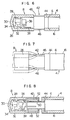
- the vibration insulator 42 can take a concrete form as shown in Fig. 6.
- the vibration insulator 42 comprises a plurality of rods 46 of a relatively small diameter each having opposed ends rigidly connected to the body 26 of the vibration heading unit 8 and the connector 44, respectively.
- the rods 46 are equidistantly spaced from each other and circumferentially arranged about the central axis of the body 26.
- the lateral rigidity is relatively small and therefore when the body 26 of the unit 8 is laterally vibrated, the insulator 42 can be easily deformed as shown in Fig. 7 by broken lines thereby to reduce or damp the vibration transmitted to the pipe 4 to be embedded under ground, while the longitudinal rigidity of the insulator 42 is relatively large, and therefore the propelling force transmitted through the pipe 4 can be positively transmitted to the body 26 of the vibration heading unit 8.
- the vibration insulator 42 can take an alternative structure as shown in Fig. 8.
- the vibration insulator 42 comprises a cylindrical extension 48 of the body 26 of the vibration heading unit 8 at the rear end thereof, a cylindrical extension 50 of the connector 44 at the front end thereof, and a plurality of small diameter rods 52 each having opposed ends rigidly connected to the extensions 48 and 50, respectively.
- the rods 52 are equidistantly spaced from each other and circumferentially arranged about the central axis of the body 26.
- vibration insulator 42 may be provided with a cover for preventing soil from entering into the interior of the insulator 42.
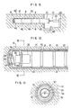
- FIG. 6 A still further embodiment of the apparatus for carrying out the method of embedding a pipe under ground according to the present invention will be explained with reference to Figs. 9 to 11.
- the apparatus according to this embodiment is generally designated by reference numeral 60 and those component elements similar to those shown in Figs. 1 and 2 and Figs. 4 and 5 are denoted by like reference numerals, respectively.
- the pipe embedding apparatus 60 further comprises means 62 for supplying the earth adjacent to the vibration heading unit 8 with a liquid for reducing the strength of the earth and converting the earth into slurry.
- This liquid supply means 62 includes liquid supply ports 64 formed in the forward end of the body 26 of the vibration heading unit 8, which liquid supply ports 64 are connected through liquid supply hoses 66 to a liquid supply source (not shown) such as a pump provided in the working pit 22.
- the working pit 22 contains a slurry pool 68.
- This pipe embedding apparatus 60 operates in such a manner than upon rotation of the motor 36, the centrifugal force of the eccentric weight 32 causes the central axis of the body 26 to revolve around the longitudinal axis of the pipe 4 to be embedded as in the aforementioned embodiment.
- a liquid such as water is supplied to the liquid supply ports 64 through the liquid supply hoses 66, and the water is then supplied to the earth 14 adjacent to the forward end of the vibration heading unit 8.
- the earth 14 in the vicinity of the forward end of the vibration heading unit 8 is vibrated while water penetrates soil particles of the earth, thus greatly reducing the strength of the earth 14.
- the earth 14 in the vicinity of the forward end of the vibration heading unit 8 is mixed with water and rapidly connected into slurry.
- the slurry 70 formed in the vicinity of the forward end of the vibration heading unit 8 flows out to the working pit 22 through the gap and is received in the slurry pool 68.
- the slurry 70 formed in the vicinity of the forward end of the vibration heading unit 8 flows out through the gap between the vibration heading unit 8 and pipe 4 and the surrounding earth 14, and therefore the surrounding resistance including the frictional force and the adhesion between the vibration heading unit 8 and pipe 4 and the surrounding earth 14 is reduced substantially to zero.
- the result is that the propelling force to be applied to the pipe 4 from the backward end 10 thereof is greatly reduced.
- water may be used as the liquid to be discharged by way of the liquid supply port 64.
- bentonite solution may preferably be used as the earth is effectively converted into slurry and the resulting slurry flows out to the working pit more easily.
Landscapes
- Engineering & Computer Science (AREA)
- Life Sciences & Earth Sciences (AREA)
- Geology (AREA)
- Mining & Mineral Resources (AREA)
- Physics & Mathematics (AREA)
- Environmental & Geological Engineering (AREA)
- Fluid Mechanics (AREA)
- General Life Sciences & Earth Sciences (AREA)
- Geochemistry & Mineralogy (AREA)
- Mechanical Engineering (AREA)
- Excavating Of Shafts Or Tunnels (AREA)
Claims (6)
Applications Claiming Priority (6)
| Application Number | Priority Date | Filing Date | Title |
|---|---|---|---|
| JP56007258A JPS57123394A (en) | 1981-01-22 | 1981-01-22 | Pipe burrying apparatus |
| JP56007256A JPS57123392A (en) | 1981-01-22 | 1981-01-22 | Method of and apparatus for burrying pipes |
| JP7256/81 | 1981-01-22 | ||
| JP7257/81 | 1981-01-22 | ||
| JP725781A JPS57123393A (en) | 1981-01-22 | 1981-01-22 | Pipe burrying apparatus |
| JP7258/81 | 1981-01-22 |
Publications (2)
| Publication Number | Publication Date |
|---|---|
| EP0057089A1 EP0057089A1 (fr) | 1982-08-04 |
| EP0057089B1 true EP0057089B1 (fr) | 1986-04-09 |
Family
ID=27277533
Family Applications (1)
| Application Number | Title | Priority Date | Filing Date |
|---|---|---|---|
| EP19820300313 Expired EP0057089B1 (fr) | 1981-01-22 | 1982-01-21 | Méthode et système pour poser des tuyaux dans le sol |
Country Status (2)
| Country | Link |
|---|---|
| EP (1) | EP0057089B1 (fr) |
| DE (1) | DE3270340D1 (fr) |
Families Citing this family (4)
| Publication number | Priority date | Publication date | Assignee | Title |
|---|---|---|---|---|
| US4576515A (en) * | 1982-09-20 | 1986-03-18 | Nippon Telegraph & Telephone Public Corp. | Pipe laying apparatus |
| JPS60181490A (ja) * | 1984-02-24 | 1985-09-17 | 日本電信電話株式会社 | 管埋設装置 |
| GB8429287D0 (en) * | 1984-11-20 | 1984-12-27 | Alh Syst Ltd | Mole |
| DK2772606T3 (en) * | 2013-02-27 | 2015-04-27 | Eurodrill Gmbh | Drive device and method of operating a drive device |
Family Cites Families (3)
| Publication number | Priority date | Publication date | Assignee | Title |
|---|---|---|---|---|
| DE1634637A1 (de) * | 1965-06-22 | 1970-07-02 | Thyssengas Ag | Einrichtung zum Durchpressen von Schutzrohren im Rohrleitungsbau |
| DE1941993B2 (de) * | 1969-08-18 | 1972-03-23 | Vorrichtung zum einspuelen von bauelementen | |
| JPS52105611A (en) * | 1976-03-02 | 1977-09-05 | Komatsu Mfg Co Ltd | Drilling apparatus |
-
1982
- 1982-01-21 DE DE8282300313T patent/DE3270340D1/de not_active Expired
- 1982-01-21 EP EP19820300313 patent/EP0057089B1/fr not_active Expired
Also Published As
| Publication number | Publication date |
|---|---|
| DE3270340D1 (en) | 1986-05-15 |
| EP0057089A1 (fr) | 1982-08-04 |
Similar Documents
| Publication | Publication Date | Title |
|---|---|---|
| EP0122540B1 (fr) | Procédé et installation de poussée pour bouclier de tunnel | |
| EP0155990B1 (fr) | Appareil pour la pose de tuyaux | |
| EP0057089B1 (fr) | Méthode et système pour poser des tuyaux dans le sol | |
| JPH1150443A (ja) | 地中固結体築造装置及び地中固結体築造工法 | |
| JP3249752B2 (ja) | 切削ビットを用いた掘削工法及び掘削装置 | |
| JPS594029B2 (ja) | 地盤の圧密強化を同時に行う貫通配管工法および装置 | |
| JP2004060163A (ja) | シートパイル埋込補助装置とその方法 | |
| JP2602172B2 (ja) | 穿孔機 | |
| JP2991819B2 (ja) | 地中推進装置及び地中推進方法 | |
| JPS60164510A (ja) | 削孔工法 | |
| JP2889381B2 (ja) | トンネルの一次覆工方法 | |
| JP3161691B2 (ja) | 地下埋設体の先導孔掘削装置 | |
| KR101608960B1 (ko) | 분출 회전식 지중 굴진 장치 | |
| JP2521303Y2 (ja) | シールド掘進機 | |
| JP3253544B2 (ja) | 中折れ式の管推進機 | |
| JP2935486B2 (ja) | 管推進工法及びその装置 | |
| JPH09144459A (ja) | 改良型併用杭打機 | |
| JPH0745796B2 (ja) | 土砂の掘削及び搬出装置 | |
| JPS6226399B2 (fr) | ||
| JPH0427357B2 (fr) | ||
| JP2583205B2 (ja) | 既設埋設管の更新方法 | |
| JPS58123999A (ja) | 掘削推進装置 | |
| JPH0370080B2 (fr) | ||
| JPH108889A (ja) | オーガ推進工法 | |
| JPH02183093A (ja) | 小口径管地中埋設機械の先導管装置 |
Legal Events
| Date | Code | Title | Description |
|---|---|---|---|
| PUAI | Public reference made under article 153(3) epc to a published international application that has entered the european phase |
Free format text: ORIGINAL CODE: 0009012 |
|
| AK | Designated contracting states |
Designated state(s): DE FR GB |
|
| 17P | Request for examination filed |
Effective date: 19830129 |
|
| GRAA | (expected) grant |
Free format text: ORIGINAL CODE: 0009210 |
|
| AK | Designated contracting states |
Kind code of ref document: B1 Designated state(s): DE FR GB |
|
| REF | Corresponds to: |
Ref document number: 3270340 Country of ref document: DE Date of ref document: 19860515 |
|
| ET | Fr: translation filed | ||
| PLBE | No opposition filed within time limit |
Free format text: ORIGINAL CODE: 0009261 |
|
| STAA | Information on the status of an ep patent application or granted ep patent |
Free format text: STATUS: NO OPPOSITION FILED WITHIN TIME LIMIT |
|
| 26N | No opposition filed | ||
| PGFP | Annual fee paid to national office [announced via postgrant information from national office to epo] |
Ref country code: FR Payment date: 19941122 Year of fee payment: 14 |
|
| PGFP | Annual fee paid to national office [announced via postgrant information from national office to epo] |
Ref country code: GB Payment date: 19950111 Year of fee payment: 14 |
|
| PGFP | Annual fee paid to national office [announced via postgrant information from national office to epo] |
Ref country code: DE Payment date: 19950330 Year of fee payment: 14 |
|
| PG25 | Lapsed in a contracting state [announced via postgrant information from national office to epo] |
Ref country code: GB Effective date: 19960121 |
|
| GBPC | Gb: european patent ceased through non-payment of renewal fee |
Effective date: 19960121 |
|
| PG25 | Lapsed in a contracting state [announced via postgrant information from national office to epo] |
Ref country code: FR Effective date: 19960930 |
|
| PG25 | Lapsed in a contracting state [announced via postgrant information from national office to epo] |
Ref country code: DE Effective date: 19961001 |
|
| REG | Reference to a national code |
Ref country code: FR Ref legal event code: ST |