EP0057729A1 - Indicateur d'etat de chauffage pour un four de cuisson utilisant un tube d'affichage fluorescent multicolore - Google Patents
Indicateur d'etat de chauffage pour un four de cuisson utilisant un tube d'affichage fluorescent multicolore Download PDFInfo
- Publication number
- EP0057729A1 EP0057729A1 EP81902251A EP81902251A EP0057729A1 EP 0057729 A1 EP0057729 A1 EP 0057729A1 EP 81902251 A EP81902251 A EP 81902251A EP 81902251 A EP81902251 A EP 81902251A EP 0057729 A1 EP0057729 A1 EP 0057729A1
- Authority
- EP
- European Patent Office
- Prior art keywords
- heating
- temperature
- cooking
- display
- oven
- Prior art date
- Legal status (The legal status is an assumption and is not a legal conclusion. Google has not performed a legal analysis and makes no representation as to the accuracy of the status listed.)
- Withdrawn
Links
Images


Classifications
-
- F—MECHANICAL ENGINEERING; LIGHTING; HEATING; WEAPONS; BLASTING
- F24—HEATING; RANGES; VENTILATING
- F24C—DOMESTIC STOVES OR RANGES ; DETAILS OF DOMESTIC STOVES OR RANGES, OF GENERAL APPLICATION
- F24C7/00—Stoves or ranges heated by electric energy
- F24C7/08—Arrangement or mounting of control or safety devices
-
- H—ELECTRICITY
- H05—ELECTRIC TECHNIQUES NOT OTHERWISE PROVIDED FOR
- H05B—ELECTRIC HEATING; ELECTRIC LIGHT SOURCES NOT OTHERWISE PROVIDED FOR; CIRCUIT ARRANGEMENTS FOR ELECTRIC LIGHT SOURCES, IN GENERAL
- H05B6/00—Heating by electric, magnetic or electromagnetic fields
- H05B6/64—Heating using microwaves
- H05B6/6435—Aspects relating to the user interface of the microwave heating apparatus
-
- H—ELECTRICITY
- H05—ELECTRIC TECHNIQUES NOT OTHERWISE PROVIDED FOR
- H05B—ELECTRIC HEATING; ELECTRIC LIGHT SOURCES NOT OTHERWISE PROVIDED FOR; CIRCUIT ARRANGEMENTS FOR ELECTRIC LIGHT SOURCES, IN GENERAL
- H05B6/00—Heating by electric, magnetic or electromagnetic fields
- H05B6/64—Heating using microwaves
- H05B6/6447—Method of operation or details of the microwave heating apparatus related to the use of detectors or sensors
- H05B6/645—Method of operation or details of the microwave heating apparatus related to the use of detectors or sensors using temperature sensors
-
- H—ELECTRICITY
- H05—ELECTRIC TECHNIQUES NOT OTHERWISE PROVIDED FOR
- H05B—ELECTRIC HEATING; ELECTRIC LIGHT SOURCES NOT OTHERWISE PROVIDED FOR; CIRCUIT ARRANGEMENTS FOR ELECTRIC LIGHT SOURCES, IN GENERAL
- H05B6/00—Heating by electric, magnetic or electromagnetic fields
- H05B6/64—Heating using microwaves
- H05B6/647—Aspects related to microwave heating combined with other heating techniques
- H05B6/6482—Aspects related to microwave heating combined with other heating techniques combined with radiant heating, e.g. infrared heating
-
- H—ELECTRICITY
- H05—ELECTRIC TECHNIQUES NOT OTHERWISE PROVIDED FOR
- H05B—ELECTRIC HEATING; ELECTRIC LIGHT SOURCES NOT OTHERWISE PROVIDED FOR; CIRCUIT ARRANGEMENTS FOR ELECTRIC LIGHT SOURCES, IN GENERAL
- H05B6/00—Heating by electric, magnetic or electromagnetic fields
- H05B6/64—Heating using microwaves
- H05B6/66—Circuits
Definitions
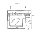
- This invention relates to means for displaying the heating condition of a heating cooking apparatus such as a microwave oven.
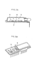
- a fluorescent display tube has a structure as shown in Figs. 2A and 2B, and thermions emitted from a cathode 5 are accelerated by a positive voltage applied across grids 6 and anodes 7 to stimulate and cause fluorescence of a fluorescent paint 8 coated on the anodes 7. The voltage is selectively applied across the grids 6 and the anodes 7 so as to display desired figures, characters, symbols and graphics.
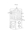
- Fig. 3 shows an example of a control panel in which two fluorescent display tubes are used.
- One of the fluorescent display tubes 9 includes a cooking mode display part 10 and a time display part 11, and the other fluorescent display tube 13 provides a temperature display part 14. Because of the provision of two fluorescent display tubes, the control part has been complex resulting in poor controllability.
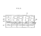
- Fig. 4 shows a connection pattern of a single multicolored fluorescent display tube 12 which includes therein a cooking mode display part 15, a time display part 16, a temperature display part 24 and a temperature . scale display part 23.
- a fluorescent paint whose fluorescent color is green is coated on characters "Hi” 19 (a display indicating a high microwave output), "Lo” 20 (a display indicating a low microwave output), "GRILL” 21 (cooking by a heater subsequent to cooking with a high microwave output), and segments of individual digits
- a fluorescent paint whose color is red is coated on characters "OVEN" 22 (cooking by the heater) and segments of the temperature scale display part 23 and temperature display part 24.
- the cathode of "OVEN” 22 and the cathode of the temperature scale display part 23 are connected within the display tube. Therefore, when the "OVEN" mode is selected, the "OVEN" display part 22 and the temperature scale display part 23 emit light simultaneously so that the purpose of demanding the temperature input can also be attained.
- the temperature display segments are controlled by signal conductors extending from terminals R 7 - R 10 and signal conductors extending from terminals R 3 - R ⁇ .
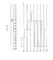
- Fig. 6 shows the timing chart of output voltage levels at the terminals R O - R 3 and terminals R 7 - R 10 when "200°C" is displayed.
- the fluorescent paint whose color is red is also coated on the anode segments of the temperature scale.
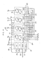
- Fig. 7 shows one form of an electrical circuit used for the practice of the present invention.
- a microcomputer 25 controls this systems.
- Current supply to the electric heater 4 is controlled by a triac 26 which is turned on-off by an output terminal R 5 of the microcomputer 25 and an electronic circuit 27.
- a thermistor 28 output terminals R 11 - R 15 of the microcomputer 25, a D-A converter 29 and a comparator 30 sense the temperature, and, on the basis thereof, the microcomputer 25 judges as to whether or not its output should appear at the terminal R 5 .
- excitation of the magnetron 1 is controlled by turning on and off the primary side of a high-voltage transformer 32 by an output terminal R 6 of the microcomputer 25 and an electronic circuit 31. As soon as the primary side is closed, a high voltage is induced in the secondary side thereby exciting the magnetron 1.
- the heater 4 is selected as the heating source, the temperature scale luminescens in red. No luminescence occurs when the magnetron 1 is selected.
- the grid voltage for a multicolored fluorescent display tube 33 is sequentially supplied from terminals R 3 - R of the microcomputer 25, and the anode voltage is supplied in parallel from terminals 0 0 - 0 7 .
- a temperature key 35 When a temperature key 35 is depressed after selection of "OVEN" by a cooking mode key 34, the number of times of depression or the duration of depression is counted to display the set temperature. After depression of a time key 36, a start key 37 is depressed.
- the signal output from the microcomputer 25 is controlled so that, with the rise of the internal temperature of the oven, the segments corresponding to the present internal temperature make flashing, and, thus, both of the set temperature and the present temperature are displayed on the same temperature display part.
- the segments corresponding to that temperature only are turned on or make flashing so as to display the oven internal temperature in the form of a bar.
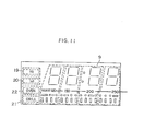
- Fig. 8 illustrates that a status part indicating the cooking condition is additionally disposed above the time display part.
- the color of light emitted from that part differs from those of the other display parts and differs also from that of the figure display part.
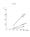
- Fig. 9 shows a circuit for driving the fluorescent display tube above described. Output voltages from terminals R 16 - R 20 and terminals 0 8 - O 11 are raised by drivers 39 and 40 before being applied to the multicolored fluorescent display tube. This is because the luminous efficacy differs depending on fluorescent paints as shown in Fig. 10, and it is therefore necessary to increase the luminance of a paint having a poor luminous efficacy.
- Fig. 11 shows another example in which the display parts emit different colors corresponding to the heating parameters.
- a single multicolored fluorescent display tube is employed to display in plural colors the cooking condition under microwave heating, the cooking condition under heating with the heater, the time setting and the temperature setting. Therefore, the present invention can provide a heating cooking apparatus in which the display is clearly visible and can be read without any error and which is free from mal- handling.
Landscapes
- Physics & Mathematics (AREA)
- Electromagnetism (AREA)
- Engineering & Computer Science (AREA)
- Human Computer Interaction (AREA)
- Chemical & Material Sciences (AREA)
- Combustion & Propulsion (AREA)
- Mechanical Engineering (AREA)
- General Engineering & Computer Science (AREA)
- Electric Ovens (AREA)
- Control Of Indicators Other Than Cathode Ray Tubes (AREA)
- Cathode-Ray Tubes And Fluorescent Screens For Display (AREA)
- Devices For Indicating Variable Information By Combining Individual Elements (AREA)
- Control Of High-Frequency Heating Circuits (AREA)
Abstract
Dans ce four de cuisson, un indicateur du mode de cuisson indique le mode de cuisson a la chaleur ou par micro-ondes, un indicateur d'echelle de temperature (23) indique la temperature de consigne de cuisson, un indicateur de temperature (24) indique la temperature de cuisson reelle, et un indicateur de temps (16) indique le temps de cuisson. La variete des informations est indiquee en plusieurs couleurs dans un tube d'affichage fluorescent multicolore permettant de les voir et les lire plus facilement et sans erreur dans un four de cuisson a micro-ondes ayant un dispositif de chauffage.
Applications Claiming Priority (2)
| Application Number | Priority Date | Filing Date | Title |
|---|---|---|---|
| JP118025/80 | 1980-08-19 | ||
| JP1980118025U JPS5740007U (fr) | 1980-08-19 | 1980-08-19 |
Publications (2)
| Publication Number | Publication Date |
|---|---|
| EP0057729A1 true EP0057729A1 (fr) | 1982-08-18 |
| EP0057729A4 EP0057729A4 (fr) | 1983-04-06 |
Family
ID=14726198
Family Applications (1)
| Application Number | Title | Priority Date | Filing Date |
|---|---|---|---|
| EP19810902251 Withdrawn EP0057729A4 (fr) | 1980-08-19 | 1981-08-17 | Indicateur d'etat de chauffage pour un four de cuisson utilisant un tube d'affichage fluorescent multicolore. |
Country Status (6)
| Country | Link |
|---|---|
| EP (1) | EP0057729A4 (fr) |
| JP (1) | JPS5740007U (fr) |
| KR (2) | KR830006632A (fr) |
| AU (1) | AU535857B2 (fr) |
| CA (1) | CA1183908A (fr) |
| WO (1) | WO1982000703A1 (fr) |
Cited By (2)
| Publication number | Priority date | Publication date | Assignee | Title |
|---|---|---|---|---|
| GB2240421A (en) * | 1989-12-28 | 1991-07-31 | Gold Star Co | Microwave oven |
| DE19724992A1 (de) * | 1997-06-13 | 1998-12-17 | Aeg Hausgeraete Gmbh | Kochfeld mit Vakuumfluoreszenzanzeige und Gargerät mit einem solchen Kochfeld |
Family Cites Families (12)
| Publication number | Priority date | Publication date | Assignee | Title |
|---|---|---|---|---|
| JPS586903B2 (ja) * | 1975-03-28 | 1983-02-07 | 株式会社日立製作所 | ブンセキソウチヨウサンプリングソウチ |
| US4162422A (en) * | 1975-10-31 | 1979-07-24 | Futaba Denshi Kogyo K.K. | Composite digital and analogue fluorescent display panel device |
| JPS5329270U (fr) * | 1976-08-20 | 1978-03-13 | ||
| US4158431A (en) * | 1976-12-10 | 1979-06-19 | Texas Instruments Incorporated | Self-test feature for appliances or electronic systems operated by microprocessor |
| DE2712325A1 (de) * | 1977-03-21 | 1978-09-28 | Siemens Ag | Optisches anzeigeelement |
| JPS5927924B2 (ja) * | 1977-11-15 | 1984-07-09 | 松下電器産業株式会社 | プログラムタイマ−付加熱装置 |
| JPS54148573A (en) * | 1978-05-15 | 1979-11-20 | Casio Comput Co Ltd | Electronic watch |
| JPS54156778A (en) * | 1978-05-30 | 1979-12-11 | Hitachi Netsu Kigu Kk | Food heater |
| JPS5517006A (en) * | 1978-07-19 | 1980-02-06 | Hitachi Heating Appliance Co Ltd | High frequency heater |
| US4303913A (en) * | 1978-08-25 | 1981-12-01 | Matsushita Electric Industrial Co., Ltd. | Fluorescent display device and display apparatus using the same |
| JPS5551892U (fr) * | 1978-10-03 | 1980-04-05 | ||
| JPS55103679U (fr) * | 1979-01-09 | 1980-07-19 |
-
1980
- 1980-08-19 JP JP1980118025U patent/JPS5740007U/ja active Pending
-
1981
- 1981-08-17 AU AU74560/81A patent/AU535857B2/en not_active Ceased
- 1981-08-17 WO PCT/JP1981/000179 patent/WO1982000703A1/fr not_active Ceased
- 1981-08-17 EP EP19810902251 patent/EP0057729A4/fr not_active Withdrawn
- 1981-08-17 KR KR1019810002973A patent/KR830006632A/ko not_active Withdrawn
- 1981-08-18 CA CA000384076A patent/CA1183908A/fr not_active Expired
-
1984
- 1984-09-14 KR KR2019840009033U patent/KR850000429Y1/ko not_active Expired
Cited By (3)
| Publication number | Priority date | Publication date | Assignee | Title |
|---|---|---|---|---|
| GB2240421A (en) * | 1989-12-28 | 1991-07-31 | Gold Star Co | Microwave oven |
| GB2240421B (en) * | 1989-12-28 | 1994-04-27 | Gold Star Co | Microwave oven |
| DE19724992A1 (de) * | 1997-06-13 | 1998-12-17 | Aeg Hausgeraete Gmbh | Kochfeld mit Vakuumfluoreszenzanzeige und Gargerät mit einem solchen Kochfeld |
Also Published As
| Publication number | Publication date |
|---|---|
| JPS5740007U (fr) | 1982-03-04 |
| EP0057729A4 (fr) | 1983-04-06 |
| WO1982000703A1 (fr) | 1982-03-04 |
| AU535857B2 (en) | 1984-04-05 |
| KR830006632A (ko) | 1983-09-28 |
| AU7456081A (en) | 1982-03-17 |
| KR850000429Y1 (ko) | 1985-03-18 |
| CA1183908A (fr) | 1985-03-12 |
Similar Documents
| Publication | Publication Date | Title |
|---|---|---|
| US4385260A (en) | Bargraph display | |
| GB2160694A (en) | Cooking apparatus | |
| EP0019276B1 (fr) | Appareil de chauffage avec minuterie programmable | |
| CA1130362A (fr) | Dispositif d'affichage fluorescent a melange de phosphore multichrome | |
| EP0057729A1 (fr) | Indicateur d'etat de chauffage pour un four de cuisson utilisant un tube d'affichage fluorescent multicolore | |
| KR900000669B1 (ko) | 방전등의 광도 제어용 작동장치 | |
| US4791337A (en) | Lighting method for vacuum fluorescent display with reduced flickering | |
| US4278917A (en) | Driving circuit for fluorescent display device | |
| US4326150A (en) | Cathode ray tube device for display system | |
| JPS59191816A (ja) | 加熱装置 | |
| JPH03111886A (ja) | Ledバックライト構造 | |
| US4987556A (en) | Heating cooking appliance with relay testing | |
| JP3382904B2 (ja) | 液晶表示装置 | |
| US4658186A (en) | Control apparatus for fluorescent display tube | |
| JPH026419B2 (fr) | ||
| KR200182551Y1 (ko) | 전자렌지의 조리시간 표시장치 | |
| JPS58220179A (ja) | 多色「けい」光表示装置 | |
| KR100274240B1 (ko) | 형광표시관 | |
| JPS5560258A (en) | Plural color fluorescent display tube | |
| JPH0590885U (ja) | マイクロ波加熱装置 | |
| JPS57124631A (en) | Heating cooker | |
| JPH05288352A (ja) | 加熱調理器 | |
| JPS58140526A (ja) | 調理器 | |
| JP2649754B2 (ja) | 情報表示装置 | |
| KR100484095B1 (ko) | 형광표시관 |
Legal Events
| Date | Code | Title | Description |
|---|---|---|---|
| PUAI | Public reference made under article 153(3) epc to a published international application that has entered the european phase |
Free format text: ORIGINAL CODE: 0009012 |
|
| 17P | Request for examination filed |
Effective date: 19820416 |
|
| AK | Designated contracting states |
Designated state(s): DE FR GB SE |
|
| STAA | Information on the status of an ep patent application or granted ep patent |
Free format text: STATUS: THE APPLICATION HAS BEEN WITHDRAWN |
|
| 18W | Application withdrawn |
Withdrawal date: 19841107 |
|
| RIN1 | Information on inventor provided before grant (corrected) |
Inventor name: NIWA, TAKASHI |