EP0057817A2 - Tachéographe - Google Patents
Tachéographe Download PDFInfo
- Publication number
- EP0057817A2 EP0057817A2 EP82100182A EP82100182A EP0057817A2 EP 0057817 A2 EP0057817 A2 EP 0057817A2 EP 82100182 A EP82100182 A EP 82100182A EP 82100182 A EP82100182 A EP 82100182A EP 0057817 A2 EP0057817 A2 EP 0057817A2
- Authority
- EP
- European Patent Office
- Prior art keywords
- speed
- pendulum
- tachograph
- vibrating
- vibrating pendulum
- Prior art date
- Legal status (The legal status is an assumption and is not a legal conclusion. Google has not performed a legal analysis and makes no representation as to the accuracy of the status listed.)
- Granted
Links
- 230000009471 action Effects 0.000 claims abstract description 8
- 230000001419 dependent effect Effects 0.000 claims description 4
- 230000005540 biological transmission Effects 0.000 claims description 3
- 230000010355 oscillation Effects 0.000 abstract description 2
- 238000010586 diagram Methods 0.000 description 8
- 230000007246 mechanism Effects 0.000 description 3
- 238000009434 installation Methods 0.000 description 2
- 210000000056 organ Anatomy 0.000 description 2
- 101000579647 Penaeus vannamei Penaeidin-2a Proteins 0.000 description 1
- 230000008901 benefit Effects 0.000 description 1
- 230000015572 biosynthetic process Effects 0.000 description 1
- 230000008859 change Effects 0.000 description 1
- 238000010276 construction Methods 0.000 description 1
- 230000000694 effects Effects 0.000 description 1
- 125000000524 functional group Chemical group 0.000 description 1
- 230000008439 repair process Effects 0.000 description 1
- 230000035945 sensitivity Effects 0.000 description 1
Images
Classifications
-
- G—PHYSICS
- G01—MEASURING; TESTING
- G01P—MEASURING LINEAR OR ANGULAR SPEED, ACCELERATION, DECELERATION, OR SHOCK; INDICATING PRESENCE, ABSENCE, OR DIRECTION, OF MOVEMENT
- G01P1/00—Details of instruments
- G01P1/12—Recording devices
- G01P1/122—Speed recorders
- G01P1/125—Speed recorders with recording discs
-
- G—PHYSICS
- G07—CHECKING-DEVICES
- G07C—TIME OR ATTENDANCE REGISTERS; REGISTERING OR INDICATING THE WORKING OF MACHINES; GENERATING RANDOM NUMBERS; VOTING OR LOTTERY APPARATUS; ARRANGEMENTS, SYSTEMS OR APPARATUS FOR CHECKING NOT PROVIDED FOR ELSEWHERE
- G07C5/00—Registering or indicating the working of vehicles
- G07C5/08—Registering or indicating performance data other than driving, working, idle, or waiting time, with or without registering driving, working, idle or waiting time
- G07C5/12—Registering or indicating performance data other than driving, working, idle, or waiting time, with or without registering driving, working, idle or waiting time in graphical form
Definitions
- the invention relates to a trip control device which can be used in tachographs and which has a vibrating pendulum which responds to operational vibrations of a motor vehicle.
- the task of a tachograph is to record, in addition to other variables that characterize the operating behavior of a motor vehicle, at least speeds, distances traveled and travel times, preferably in a visually recognizable manner, and, as is generally the case, to present the travel times in the form of bar graphs for better readability.
- the solution to this problem provides that the vibrating pendulum is mechanically operatively connected to the zero position of a registration element which is arranged in the tachograph and can be deflected in a speed-dependent manner
- a preferred embodiment which is advantageously applicable to tachographs with a gear wheel drives connected to the speed measuring device, whose zero stop is selected in such a way that in its zero position it is on the one hand unencumbered by the usual torque which serves to suppress a certain initial measuring range, and on the other hand the existing gear backlash by an appropriately dimensioned on the speed register g is balanced on the attacking spring, is characterized in that the vibrating pendulum is arranged such that it serves as a stop for the speed registration member which is under the action of the play compensation spring and is easily movable within the gear play.
- the recordings of the device according to the invention can be incomplete for the desired statement and no special conditions have to be set with regard to the registration width, the requirements regarding the sensitivity of the vibrating pendulum are relatively low, so that simple design and storage of the vibrating pendulum are selected and additional force-operated means for maintaining vibrations can be dispensed with.
- the vibrating pendulum if precautions have been taken for its storage, is an optional additional device that can be installed without special installation work, where it is irrelevant whether the speed control device is only effective in the zero position of the speed registration element, whether a straight-line slide or a rotatably mounted registration arm, which may be designed with a straight handlebar, is provided as the speed registration element.
- This gear play which arises from the fact that on the one hand a gear transmission is provided between the speed measuring device and the speed registration element, on the other hand the zero stop of the speed measuring element does not take place through the speed registration element, but is placed at the input of the gear train between the speed measuring element and the speed registration element, because it causes is only balanced by a weak spring that the speed registration element is particularly easy to move in the zero position and thus the vibrating pendulum is only slightly loaded within the limits of the gear play.
- the vibrating pendulum is preferably adjusted in this case in such a way that the speed registration element under the action of the play compensation spring does not abut the zero stop of the speed measuring device but is "raised” by it against a lifting arm designed on the vibrating pendulum or a suitable transmission element when the vibrating pendulum is in its rest position located. Otherwise, the gear play due to the used play compensation spring, which causes the speed registration member to move forward and backward no flank change takes place in the driving gear, can be enlarged due to incomplete tooth shapes.
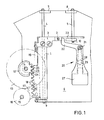
- FIG. 1 shows, in the tachograph in question, in which the trip control device according to the invention is designed, a speed registration element is provided, which in the form of a carriage 1, on which a holder 3 carrying a spring-loaded pen 2 is fastened, is slidably mounted on suitable guide rods 4 and 5 is.
- the guide rods 4 and 5, are held in a frame 6, which is essentially only indicated and freed from the elements not essential to the invention, or lugs 7, 8, 9 and 10 formed on the frame.
- FIG. 1 also shows that an axis 11 is fastened to the frame 6, which can be used in the tachograph as a prefabricated functional group together with the elements mounted or arranged on it.
- a gear set 12, 13 is mounted, which on the one hand engages via the gear 12 with a toothing 14 formed on the slide 1, and on the other hand is gearingly connected via the gear 13 to a gear 16 fastened on the measuring mechanism shaft 15
- Gear 16 formed flag 17 and a gear 13 The provided bolt 18 represents the means for a zero stop, which is movable in this embodiment, of a speed measuring device, not shown, which operates, for example, according to the eddy current principle.
- a vibrating pendulum 20, which is pivotally mounted on a further axis 21 fastened in the frame 6 and on which a lifting arm 22 is formed, can now be adjusted in such a way that the web 23 formed on the slide 1 in the illustrated rest position of the vibrating pendulum 2o its lifting arm 22 just touches when, as shown, the gear play between the gear 14 and the carriage 1 is balanced on one side.
- the vibrating pendulum 2o can also be adjusted such that it serves as a stop for the slide 1 which is under the action of the tension spring 19 and the gear play is averaged, for example.
- the gear play usable for the vibrating movement can be increased by incomplete formation of the teeth 24, 25, 26 of the slide toothing 14 (shown in broken lines), which due to the constant one-sided play compensation by the tension spring 19 increases the accuracy which would not affect speed records.
- the pendulum mass 27 of the vibrating pendulum 20 is associated with a leg spring 28 mounted on the axis 21, the legs of which alternately bear against a bolt 29 fastened to the frame 6 when the vibrating pendulum 20 swings.
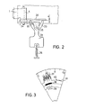
- a small play a is provided between the lever arms 32 and 33 and the actuating arm 3o, in order to assume that, in this exemplary embodiment, the slide 1 acts under the action of the measuring system spring (not shown) with a certain bias which serves to suppress a certain initial measuring range a stop 34 formed on the frame 6 rests to facilitate the swinging of the vibrating pendulum 31.
- the elastic member which cooperates with the vibrating pendulum 31, which is also pivotably mounted on an axis 35 fastened in the frame 6, in this case forms the tension spring 36.
- the section of the diagram (FIG. 3) shows, in addition to a properly recorded speed diagram 37, to which a travel time diagram 38 represented as a bar diagram and a route diagram 39 are assigned in the usual way, two of the zero lines superimposed by the speed registration element 4o and 41, which are used of the vehicle with interrupted drive connections to the tachograph.
Landscapes
- Physics & Mathematics (AREA)
- General Physics & Mathematics (AREA)
- Time Recorders, Dirve Recorders, Access Control (AREA)
- Recording Measured Values (AREA)
- Navigation (AREA)
Applications Claiming Priority (2)
| Application Number | Priority Date | Filing Date | Title |
|---|---|---|---|
| DE19813104480 DE3104480A1 (de) | 1981-02-09 | 1981-02-09 | Eine in fahrtschreibern anwendbare fahrtkontrollvorrichtung |
| DE3104480 | 1981-02-09 |
Publications (3)
| Publication Number | Publication Date |
|---|---|
| EP0057817A2 true EP0057817A2 (fr) | 1982-08-18 |
| EP0057817A3 EP0057817A3 (en) | 1982-09-01 |
| EP0057817B1 EP0057817B1 (fr) | 1987-04-08 |
Family
ID=6124376
Family Applications (1)
| Application Number | Title | Priority Date | Filing Date |
|---|---|---|---|
| EP82100182A Expired EP0057817B1 (fr) | 1981-02-09 | 1982-01-13 | Tachéographe |
Country Status (4)
| Country | Link |
|---|---|
| EP (1) | EP0057817B1 (fr) |
| JP (1) | JPH0120644Y2 (fr) |
| DE (2) | DE3104480A1 (fr) |
| ES (1) | ES509104A0 (fr) |
Cited By (2)
| Publication number | Priority date | Publication date | Assignee | Title |
|---|---|---|---|---|
| FR2585491A1 (fr) * | 1985-07-26 | 1987-01-30 | Mannesmann Kienzle Gmbh | Enregistreur de route |
| FR2728679A1 (fr) * | 1994-12-22 | 1996-06-28 | Vdo Schindling | Enregistreur de route avec un moteur pas a pas prevu dans le systeme d'inscription pour les enregistrements de vitesse |
Family Cites Families (6)
| Publication number | Priority date | Publication date | Assignee | Title |
|---|---|---|---|---|
| US3132916A (en) * | 1959-10-01 | 1964-05-12 | Kienzle Apparate Gmbh | Combined speed and idling recorder for automotive vehicles and the like |
| DE1128194B (de) * | 1961-01-31 | 1962-04-19 | Kienzle Apparate Gmbh | Anordnung in Geschwindigkeitsregistrier-geraeten zur Erzeugung einer Leitlinie |
| DE1232379B (de) * | 1965-04-23 | 1967-01-12 | Kienzle Apparate Gmbh | Ruettelvorrichtung fuer Fahrtschreiber und aehnliche Registriergeraete |
| DE2026513A1 (de) * | 1965-07-15 | 1971-12-09 | Kienzle Apparate Gmbh | Steuereinrichtung für den Rüttelantrieb von Registriermitteln in einem Fahrtschreiber oder ähnlichem Registriergerät |
| DE1260211B (de) * | 1965-07-15 | 1968-02-01 | Kienzle Apparate Gmbh | Steuereinrichtung fuer den Ruettelantrieb von Registriermitteln in einem Fahrtschreiber oder aehnlichem Registriergeraet |
| DE1673375A1 (de) * | 1967-05-12 | 1971-06-16 | Moto Meter Gmbh | Einrichtung in Geschwindigkeitsregistriergeraeten zum Kennzeichnen von Fahr-und Haltezeiten |
-
1981
- 1981-02-09 DE DE19813104480 patent/DE3104480A1/de not_active Withdrawn
-
1982
- 1982-01-13 EP EP82100182A patent/EP0057817B1/fr not_active Expired
- 1982-01-13 DE DE8282100182T patent/DE3276031D1/de not_active Expired
- 1982-01-27 ES ES509104A patent/ES509104A0/es active Granted
- 1982-02-08 JP JP1982015317U patent/JPH0120644Y2/ja not_active Expired
Cited By (2)
| Publication number | Priority date | Publication date | Assignee | Title |
|---|---|---|---|---|
| FR2585491A1 (fr) * | 1985-07-26 | 1987-01-30 | Mannesmann Kienzle Gmbh | Enregistreur de route |
| FR2728679A1 (fr) * | 1994-12-22 | 1996-06-28 | Vdo Schindling | Enregistreur de route avec un moteur pas a pas prevu dans le systeme d'inscription pour les enregistrements de vitesse |
Also Published As
| Publication number | Publication date |
|---|---|
| ES8301374A1 (es) | 1982-12-16 |
| EP0057817A3 (en) | 1982-09-01 |
| JPS57129113U (fr) | 1982-08-12 |
| JPH0120644Y2 (fr) | 1989-06-21 |
| DE3104480A1 (de) | 1982-08-19 |
| ES509104A0 (es) | 1982-12-16 |
| DE3276031D1 (en) | 1987-05-14 |
| EP0057817B1 (fr) | 1987-04-08 |
Similar Documents
| Publication | Publication Date | Title |
|---|---|---|
| EP0012223B1 (fr) | Enregistreur de route | |
| CH448578A (de) | Registriergerät in einem Fahrzeug | |
| EP0057817B1 (fr) | Tachéographe | |
| DE2249628C3 (de) | Vorrichtung zum Einwirken auf ein Registrierorgan in einem Fahrtschreiber | |
| EP0126374B1 (fr) | Dispositif d'enregistrement pour enregistreur de route | |
| EP0010644A1 (fr) | Dispositif d'effacement d'un support d'enregistrement qui fourniet, par l'action d'un organe d'enregistrement magnétique, des enregistrements visibles | |
| DE485355C (de) | Uhr mit doppelt wirkendem Pendelaufzug fuer Kraftfahrzeuge u. dgl. | |
| DE1817341C (de) | Fahrtschreiber für Fahrzeuge | |
| DE556505C (de) | Durchfahrtzeiten- und Geschwindigkeitsschreiber | |
| DE593880C (de) | Kontrollvorrichtung mit Schwingkoerper fuer Fahrzeuge | |
| DE484552C (de) | Federnde Abstuetzung der angetriebenen Hinterraeder von Motorschleppern | |
| AT148099B (de) | Registrierende Fahrtkontrollvorrichtung mit schwingendem Körper und Uhrwerk. | |
| DE593599C (de) | Elektromagnetische Vorrichtung zum Aufzeichnen der im Augenblick eines Zusammenstosses gefahrenen Geschwindigkeit | |
| DE611951C (de) | Lokomotivlenkgestell mit radial einstellbarer Laufachse und ideellem Drehpunkt | |
| DE393175C (de) | Registrierapparat | |
| DE3445581C1 (de) | Druckender Streckenzähler | |
| DE142967C (fr) | ||
| DE1176903B (de) | Tachograph fuer Fahrzeuge | |
| DE2943056A1 (de) | Registrieranordnung fuer fahrtschreiber zum aufzeichnen von dem geschwindigkeitsdiagramm ueberlagerten zeitmarken | |
| DE463679C (de) | Kontrollapparat fuer Kraftfahrzeuge zur UEberwachung der Versicherungs- oder Steuerbetraege nach Massgabe der von dem Fahrzeug zurueckgelegten Wegstrecken | |
| DE694768C (de) | Fahrueberwachungsvorrichtung, insbesondere fuer Kraftfahrzeuge | |
| DE714457C (de) | Fahrueberwachungsvorrichtung, insbesondere fuer Kraftfahrzeuge | |
| DE857396C (de) | Gleis-Anschlaghebelanordnung zur Bewegung von Betaetigungsorganen an Eisenbahn-Sicherungseinrichtungen | |
| DE558001C (de) | Registriervorrichtung fuer Fahrzeuge | |
| DE708046C (de) | Im Achslagergehaeuse von Fahrzeugen fest eingebautes Zaehlwerk zum Zaehlen der Achsenumdrehungen |
Legal Events
| Date | Code | Title | Description |
|---|---|---|---|
| PUAI | Public reference made under article 153(3) epc to a published international application that has entered the european phase |
Free format text: ORIGINAL CODE: 0009012 |
|
| PUAL | Search report despatched |
Free format text: ORIGINAL CODE: 0009013 |
|
| AK | Designated contracting states |
Designated state(s): CH DE FR GB IT LI |
|
| AK | Designated contracting states |
Designated state(s): CH DE FR GB IT LI |
|
| 17P | Request for examination filed |
Effective date: 19821216 |
|
| RAP1 | Party data changed (applicant data changed or rights of an application transferred) |
Owner name: MANNESMANN KIENZLE GMBH |
|
| GRAA | (expected) grant |
Free format text: ORIGINAL CODE: 0009210 |
|
| AK | Designated contracting states |
Kind code of ref document: B1 Designated state(s): CH DE FR GB IT LI |
|
| ITF | It: translation for a ep patent filed | ||
| REF | Corresponds to: |
Ref document number: 3276031 Country of ref document: DE Date of ref document: 19870514 |
|
| ET | Fr: translation filed | ||
| PLBE | No opposition filed within time limit |
Free format text: ORIGINAL CODE: 0009261 |
|
| STAA | Information on the status of an ep patent application or granted ep patent |
Free format text: STATUS: NO OPPOSITION FILED WITHIN TIME LIMIT |
|
| 26N | No opposition filed | ||
| REG | Reference to a national code |
Ref country code: GB Ref legal event code: 746 |
|
| ITPR | It: changes in ownership of a european patent |
Owner name: OFFERTA DI LICENZA AL PUBBLICO |
|
| REG | Reference to a national code |
Ref country code: FR Ref legal event code: DL |
|
| PGFP | Annual fee paid to national office [announced via postgrant information from national office to epo] |
Ref country code: FR Payment date: 19921212 Year of fee payment: 12 |
|
| PGFP | Annual fee paid to national office [announced via postgrant information from national office to epo] |
Ref country code: CH Payment date: 19921215 Year of fee payment: 12 |
|
| ITTA | It: last paid annual fee | ||
| PG25 | Lapsed in a contracting state [announced via postgrant information from national office to epo] |
Ref country code: LI Effective date: 19940131 Ref country code: CH Effective date: 19940131 |
|
| PGFP | Annual fee paid to national office [announced via postgrant information from national office to epo] |
Ref country code: DE Payment date: 19940223 Year of fee payment: 13 |
|
| PG25 | Lapsed in a contracting state [announced via postgrant information from national office to epo] |
Ref country code: FR Effective date: 19940930 |
|
| REG | Reference to a national code |
Ref country code: CH Ref legal event code: PL |
|
| REG | Reference to a national code |
Ref country code: FR Ref legal event code: ST |
|
| PG25 | Lapsed in a contracting state [announced via postgrant information from national office to epo] |
Ref country code: DE Effective date: 19951003 |
|
| PGFP | Annual fee paid to national office [announced via postgrant information from national office to epo] |
Ref country code: GB Payment date: 19971211 Year of fee payment: 17 |
|
| PG25 | Lapsed in a contracting state [announced via postgrant information from national office to epo] |
Ref country code: GB Free format text: LAPSE BECAUSE OF NON-PAYMENT OF DUE FEES Effective date: 19990113 |
|
| GBPC | Gb: european patent ceased through non-payment of renewal fee |
Effective date: 19990113 |