EP0057895A2 - Vorrichtung zur direkten Zündung von heizwertarmen pulverisierten festen Brennstoffen in kalten Brennkammern - Google Patents
Vorrichtung zur direkten Zündung von heizwertarmen pulverisierten festen Brennstoffen in kalten Brennkammern Download PDFInfo
- Publication number
- EP0057895A2 EP0057895A2 EP82100715A EP82100715A EP0057895A2 EP 0057895 A2 EP0057895 A2 EP 0057895A2 EP 82100715 A EP82100715 A EP 82100715A EP 82100715 A EP82100715 A EP 82100715A EP 0057895 A2 EP0057895 A2 EP 0057895A2
- Authority
- EP
- European Patent Office
- Prior art keywords
- ignition
- igniter
- air
- main
- combustion chamber
- Prior art date
- Legal status (The legal status is an assumption and is not a legal conclusion. Google has not performed a legal analysis and makes no representation as to the accuracy of the status listed.)
- Withdrawn
Links
Images



Classifications
-
- F—MECHANICAL ENGINEERING; LIGHTING; HEATING; WEAPONS; BLASTING
- F23—COMBUSTION APPARATUS; COMBUSTION PROCESSES
- F23C—METHODS OR APPARATUS FOR COMBUSTION USING FLUID FUEL OR SOLID FUEL SUSPENDED IN A CARRIER GAS OR AIR
- F23C1/00—Combustion apparatus specially adapted for combustion of two or more kinds of fuel simultaneously or alternately, at least one kind of fuel being either a fluid fuel or a solid fuel suspended in a carrier gas or air
- F23C1/12—Combustion apparatus specially adapted for combustion of two or more kinds of fuel simultaneously or alternately, at least one kind of fuel being either a fluid fuel or a solid fuel suspended in a carrier gas or air gaseous and pulverulent fuel
-
- F—MECHANICAL ENGINEERING; LIGHTING; HEATING; WEAPONS; BLASTING
- F23—COMBUSTION APPARATUS; COMBUSTION PROCESSES
- F23D—BURNERS
- F23D1/00—Burners for combustion of pulverulent fuel
-
- F—MECHANICAL ENGINEERING; LIGHTING; HEATING; WEAPONS; BLASTING
- F23—COMBUSTION APPARATUS; COMBUSTION PROCESSES
- F23D—BURNERS
- F23D17/00—Burners for combustion simultaneously or alternately of gaseous or liquid or pulverulent fuel
- F23D17/005—Burners for combustion simultaneously or alternately of gaseous or liquid or pulverulent fuel gaseous or pulverulent fuel
Definitions
- the present invention relates to a device for direct ignition of lean atomized solid fuels in cold combustion chambers.
- These poor fuels being either coals with an ash content of up to 50%, the volatile matter content is less than 20%, the lower calorific value is of the order of 8000 kilojoules per kilogram of fuel, or lignites and peat with a moisture content of up to 65% and a lower calorific value of the order of 6000 kilojoules per kilogram of fuel.
- the ignition of solid fuels pulverized during cold starts of steam generators and when running at low loads - the word load being synonymous with the degree of use of the boiler compared to its possibilities - is achieved by the flame from rich fuels such as liquid or gaseous hydrocarbons.
- the initial ignition can, for example be carried out with Meli Oil which is followed by Fuel Oil then the main solid fuel. This assistance can last, depending on the quality of the main solid fuel, up to three hours, the time necessary to reach charges of the order of 35% to 40%, making it possible to obtain suitable flame stability.
- the device of a known installation mainly comprises a liquid fuel storage tank, pumps and shut-off valves. distribution of liquid fuel to an ignition igniter forming part of an ignition burner upstream of a combustion chamber and generally disposed along the axis of the ignition burner whose peripheral ring allows the arrival of solid fuel pulverized mixed with said primary air under pressure, an inlet of said secondary air under pressure also intervening at the level of the combustion chamber.
- the prior art device using an extra ignition in liquid fuel particularly rich in calories therefore requires only an ignition igniter whose volume is relatively small. Likewise, the combustion air only intervenes at the level of the combustion chamber because the combustion support thus produced is then sufficient.
- the object of the present invention is to propose a device which makes it possible to ignite and support the combustion of pulverized solid fuels without the use of an auxiliary fuel rich in an expensive and sometimes random supply.
- the subject of the present invention is a device for direct ignition of lean atomized solid fuels in cold combustion chambers comprising at least one ignition burner comprising at least one ignition igniter and at least one main igniter supplied with lean atomized fuel , characterized in that said ignition igniter is supplied with lean gas from a gasification station of said lean fuel.
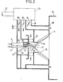
- the ignition device comprises in the same body a combustion chamber having a cylindrical-conical part, air distribution members to facilitate combustion, at least one burner ignition consisting of an ignition igniter and a main igniter, said main igniter being supplied by a pipe supplying air and atomized fuel and opening at one end, axially with respect to the cylindrical-conical part of the combustion chamber, and is characterized in that said igniter 4 'lean gas ignition is disposed upstream of said end of the piping of the atomized fuel in parallel and on the side of said piping.
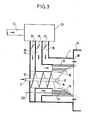
- the ignition device comprises in the same body a combustion chamber comprising a cylindrical-conical part, air distribution members to facilitate combustion, at least one burner d ignition consisting of an ignition igniter and a main igniter, said main igniter being supplied by a pipe supplying air and atomized fuel and opening out at one end, axially with respect to the cylindrical-conical part of the combustion chamber and is characterized in that at least one lean gas ignition igniter is arranged downstream of said end of the fuel spray pipe parallel to said pipe and opening onto a portion of the lateral surface of the cone belonging to said cylindro-conical surface.
- said air distribution members are preceded by an air heater operating on lean gas produced by said gasification station and supplying heated air to said ignition burner.
- said heated air supplies said ignition igniter at its inlet, at the same time as the lean gas and at its outlet, the air supplying the outlet called secondary air having been previously put into turbulence.
- the turbulence of said secondary air can be obtained by louvers for rotating said secondary air arranged perpendicular to the outlet of said lean gas ignition igniter.
- the turbulence of said secondary air is obtained by a helical ramp arranged concentrically around said piping of lean atomized fuel.
- a lean fuel gasification station 6 sends lean gas produced by transport pipes 7 to each of the ignition burners 1 through distribution valves such as 8.
- Transport pipes 7 whose flow rate is regulated by a valve regulator 9 is used to send lean gas which is burned in order to heat the air in an air heater 10 whose air is pulsed by a fan 11.
- the hot air thus produced is sent by the distribution sheaths 12 to the ignition burners 1 in order to provide them with heated combustion air since lean fuel installations require heated combustion air.
- the main burners 2 also include a circuit 13 for supplying combustion air which can possibly be heated in the same way.
- the fuel is gasified in station 6 and provides a quantity of gas whose combustion allows the ignition in a cold combustion chamber (during a cold start) or hot (during a start after a few hours off) , lean coal used in the boiler, as well as its combustion at very low loads without adding a rich fuel such as fuel oil.
- the burner 1 comprises a main igniter 16 supplied by the pipe 3 through which the lean pulverized fuel arrives mixed with primary air. This igniter is arranged at the end of the piping and it includes a diffusion cone 17. The axis of the main igniter 16 is that of the cylindro-conical part 15 and the atomized fuel is sprayed under pneumatic pressure in a cone 18 conforming to the walls of the conical part 15.
- the ignition burner 1 further comprises an actual igniter, make-up and ignition 19 supplied by the piping 7 with lean gas and by combustion air heated in from the distribution sheath 12.
- the ignition igniter 19 occupies a large volume since it operates on lean gas.
- it is placed away from the radiation of the chamber upstream from the end of the piping 3 terminated by the main igniter 16. Therefore the ignition igniter 19 is disposed in a surrounding ring sector. the main igniter 16, parallel to the axis thereof and on one side.
- the ignition igniter 19 has the particularity of being of lamellar distribution, the lean gas and the air being distributed in alternating compartments 20 and 21 (air compartment 20 and gas compartment.poor 21).
- the first ignition of the lean gas is carried out for a very short period of the order of one minute by a cane 22 supplied either by a rich gas such as propane, or by the lean gas originating from the gasification of the fuel itself .
- the air distribution members comprise a box 23 for distributing air from the distribution duct 12 for heated air, and an air distribution in ducts 24, 25, 26.
- the duct 24 is provided for transporting the air to the lean gas igniter 19 at its inlet.
- the duct 25 is provided for transporting air to the igniter 16 at its outlet.
- the duct 25 transporting the so-called secondary air also includes louvers 27 for rotating ensuring the turbulence of the secondary air.
- the duct 26 transports the so-called tertiary air opening into the combustion chamber 14 through the orifices such as 28.
- Louvre registers 29, 30, 31 make it possible to adjust the air flow rates of the conduits 24, 25, 26 respectively.
- the igniter 19 supplied with lean gas and located at the bottom of the cylindrical-conical chamber part 15 is completely protected from the radiation of the carbon flame by the secondary turbulent air during the periods when its use is not required.
- the air strips of the igniters 33, 34 allow, when these are out of service, to have an additional distribution of the combustion air of the pulverized fuel from the ignition burner.
- FIGS 4 and 5 show a possible arrangement of the burner blocks 50 consisting of an arrangement of main burners 2 arranged on either side of ignition burners 1.
- the burner blocks 50 are located in the corners of the combustion chamber. combustion 14, which is parallelepiped. Combustion air is distributed to the various burners from boxes such as 23.
- Figures 6 and 7 show another possible arrangement of the burners, the ignition burners 1 and the main burners 2 are located on a front of the combustion chamber 14.
- the combustion air from the ignition burners 1 is distributed to from the boxes 23.
- the combustion air of the main burners is distributed from boxes 230.
Landscapes
- Engineering & Computer Science (AREA)
- Chemical & Material Sciences (AREA)
- Combustion & Propulsion (AREA)
- Mechanical Engineering (AREA)
- General Engineering & Computer Science (AREA)
Applications Claiming Priority (2)
| Application Number | Priority Date | Filing Date | Title |
|---|---|---|---|
| FR8102383 | 1981-02-06 | ||
| FR8102383A FR2499681A1 (fr) | 1981-02-06 | 1981-02-06 | Dispositif d'allumage direct de combustibles solides pulverises pauvres dans des chambres de combustion froides |
Publications (2)
| Publication Number | Publication Date |
|---|---|
| EP0057895A2 true EP0057895A2 (de) | 1982-08-18 |
| EP0057895A3 EP0057895A3 (de) | 1983-04-06 |
Family
ID=9254928
Family Applications (1)
| Application Number | Title | Priority Date | Filing Date |
|---|---|---|---|
| EP82100715A Withdrawn EP0057895A3 (de) | 1981-02-06 | 1982-02-02 | Vorrichtung zur direkten Zündung von heizwertarmen pulverisierten festen Brennstoffen in kalten Brennkammern |
Country Status (5)
| Country | Link |
|---|---|
| US (1) | US4438707A (de) |
| EP (1) | EP0057895A3 (de) |
| BR (1) | BR8200538A (de) |
| FR (1) | FR2499681A1 (de) |
| ZA (1) | ZA82718B (de) |
Cited By (1)
| Publication number | Priority date | Publication date | Assignee | Title |
|---|---|---|---|---|
| EP0171788A1 (de) * | 1984-08-16 | 1986-02-19 | STEIN INDUSTRIE Société Anonyme dite: | Zündungs- und Erhaltungsbrenner für festen, fossilen und zerstäubten Brennstoff und Verbrennungskammer mit solchen Brennern |
Families Citing this family (10)
| Publication number | Priority date | Publication date | Assignee | Title |
|---|---|---|---|---|
| FR2581444B1 (fr) * | 1985-05-03 | 1988-11-10 | Charbonnages De France | Procede pour la combustion de combustibles fluides et bruleur a turbulence adapte a sa mise en oeuvre |
| GB2202234B (en) * | 1987-03-16 | 1991-09-18 | Shell Int Research | Method for starting up a partial combustion process |
| AU598147B2 (en) * | 1987-08-13 | 1990-06-14 | Connell Wagner Pty Ltd | Pulverised fuel burner |
| US5333574A (en) * | 1991-09-11 | 1994-08-02 | Mark Iv Transportation Products Corporation | Compact boiler having low NOX emissions |
| GB2348695A (en) * | 1999-04-06 | 2000-10-11 | James Engineering | Gas turbines |
| ITBO20030640A1 (it) * | 2003-10-30 | 2005-04-30 | Ampelio Lazzarin | Metodo ed impianto per l'immissione di una miscela di |
| DE202006020601U1 (de) * | 2006-06-28 | 2009-03-05 | Siemens Aktiengesellschaft | Vorrichtung für Flugstrom-Vergasungsreaktoren hoher Leistung mit Kombinationsbrenner und Mehrbrenneranordnung |
| CN101679885B (zh) | 2008-01-28 | 2013-03-27 | 国际壳牌研究有限公司 | 启动煤气化反应器的方法 |
| DE102011056655B4 (de) * | 2011-12-20 | 2013-10-31 | Alstom Technology Ltd. | Brenner zum Verbrennen eines staubförmigen Brennstoffes für einen Kessel mit Plasmazündbrenner |
| EP3130851B1 (de) * | 2015-08-13 | 2021-03-24 | General Electric Technology GmbH | System und verfahren zur bereitstellung von verbrennung in einem heizkessel |
Family Cites Families (13)
| Publication number | Priority date | Publication date | Assignee | Title |
|---|---|---|---|---|
| FR870016A (fr) * | 1940-02-08 | 1942-02-27 | Kohlenscheidungs Gmbh | Foyer à combustible pulvérisé |
| DE922297C (de) * | 1940-02-18 | 1955-01-13 | Babcock & Wilcox Dampfkessel W | Zuendbrenneranordnung bei Brennstaub-Eckenfeuerungen |
| FR871390A (fr) * | 1940-05-07 | 1942-04-22 | Kohlenscheidungs Gmbh | Foyer à poussier |
| DE928360C (de) * | 1940-05-08 | 1955-05-31 | Kohlenscheidungs Ges Mit Besch | Zuendmuffel fuer Staubfeuerungen |
| US3934522A (en) * | 1974-11-01 | 1976-01-27 | The Detroit Edison Company | Coal burning system |
| US4173189A (en) * | 1977-01-21 | 1979-11-06 | Combustion Engineering, Inc. | Boiler cold start using pulverized coal in ignitor burners |
| DE2806363C2 (de) * | 1977-02-18 | 1985-06-27 | Combustion Engineering, Inc., Windsor, Conn. | Verfahren zum Zünden der Verbrennung von Kohlenstaub |
| US4186669A (en) * | 1977-09-22 | 1980-02-05 | Cowan Frederick C | Coal burning process |
| US4150631A (en) * | 1977-12-27 | 1979-04-24 | Combustion Engineering, Inc. | Coal fired furance |
| US4221174A (en) * | 1978-05-16 | 1980-09-09 | Combustion Engineering, Inc. | Direct ignition of a fluctuating fuel stream |
| US4228747A (en) * | 1979-02-22 | 1980-10-21 | Combustion Engineering, Inc. | High energy arc ignition of pulverized coal |
| DE2933040C2 (de) * | 1979-08-16 | 1988-12-22 | L. & C. Steinmüller GmbH, 5270 Gummersbach | Verfahren zum Zünden einer Kohlenstaub-Rundbrennerflamme |
| US4241673A (en) * | 1979-11-05 | 1980-12-30 | Combustion Engineering, Inc. | Direct ignition of pulverized coal |
-
1981
- 1981-02-06 FR FR8102383A patent/FR2499681A1/fr active Granted
-
1982
- 1982-02-02 EP EP82100715A patent/EP0057895A3/de not_active Withdrawn
- 1982-02-02 BR BR8200538A patent/BR8200538A/pt unknown
- 1982-02-04 ZA ZA82718A patent/ZA82718B/xx unknown
- 1982-02-08 US US06/346,708 patent/US4438707A/en not_active Expired - Fee Related
Cited By (2)
| Publication number | Priority date | Publication date | Assignee | Title |
|---|---|---|---|---|
| EP0171788A1 (de) * | 1984-08-16 | 1986-02-19 | STEIN INDUSTRIE Société Anonyme dite: | Zündungs- und Erhaltungsbrenner für festen, fossilen und zerstäubten Brennstoff und Verbrennungskammer mit solchen Brennern |
| FR2569256A1 (fr) * | 1984-08-16 | 1986-02-21 | Stein Industrie | Bruleur d'allumage et de soutien de combustion pour combustible solide fossile pulverise, et chambre de combustion comportant de tels bruleurs |
Also Published As
| Publication number | Publication date |
|---|---|
| FR2499681A1 (fr) | 1982-08-13 |
| ZA82718B (en) | 1983-01-26 |
| US4438707A (en) | 1984-03-27 |
| EP0057895A3 (de) | 1983-04-06 |
| FR2499681B1 (de) | 1983-02-04 |
| BR8200538A (pt) | 1982-12-07 |
Similar Documents
| Publication | Publication Date | Title |
|---|---|---|
| EP1144915A1 (de) | Abfackelvorrichtung und verfahren zur gasverbrennung | |
| FR2499681A1 (fr) | Dispositif d'allumage direct de combustibles solides pulverises pauvres dans des chambres de combustion froides | |
| FR2499678A1 (fr) | Bruleur, chaudiere, ensemble les comprenant et procede pour bruler un combustible liquide | |
| CH639187A5 (fr) | Chaudiere, notamment pour installation de chauffage. | |
| EP0747462A1 (de) | Wirbelbettreaktor zur thermischen Behandlung von Abfällen | |
| EP0806609B1 (de) | Gasheizkessel mit schwingender Verbrennung | |
| FR3075932A1 (fr) | Procede d'optimisation de la limitation des emissions de poussieres pour les turbines a gaz alimentees au fioul lourd. | |
| FR3041689B1 (fr) | Dispositif de suppression, partielle voire totale, d'un panache de fumees, ainsi qu'installation de rejet de fumees a l'atmosphere comprenant un tel dispositif | |
| EP1426586B1 (de) | Turbomotor mit Holzgasgenerator | |
| FR2727747A1 (fr) | Equipement ameliore pour incineration de dechets humides | |
| FR2692966A1 (fr) | Dispositif de réchauffage par combustion de gaz chauds. | |
| FR2576395A1 (fr) | Dispositif pour la combustion de combustibles solides | |
| FR2489360A1 (fr) | Equipement auxiliaire pour gazogene a charbon | |
| WO1998044297A1 (fr) | Incinerateur et procede d'incineration de dechets liquides, pateux et solides | |
| EP0214010A1 (de) | Brenner mit Vergasungsstufe für Heizungsvorrichtung und mit einem solchen Brenner ausgerüstete Heizungsvorrichtung | |
| FR2608736A1 (fr) | Chaudiere de chauffage central a combustible solide | |
| FR2951525A1 (fr) | Procede de fonctionnement d'une chaudiere | |
| FR2710135A1 (fr) | Incinérateur à ordures ménagères et autres résidus. | |
| FR2955917A1 (fr) | Chambre de combustion pour combustibles solides, liquides, gazeux ou un melange de ceux-ci, du type torsionnelle a axe d'inclinaison variable | |
| CA1054380A (fr) | Procede pour la combustion continue de combustibles mineraux ou organiques et installation pour la mise en oeuvre de ce procede | |
| FR2515312A1 (fr) | Installation de recuperation de chaleur pour chaudiere a eau chaude et chaudiere a vapeur avec foyer a gaz | |
| BE431208A (de) | ||
| BE521336A (de) | ||
| FR1449478A (fr) | Perfectionnements apportés aux brûleurs à combustibles liquides | |
| BE516560A (de) |
Legal Events
| Date | Code | Title | Description |
|---|---|---|---|
| PUAI | Public reference made under article 153(3) epc to a published international application that has entered the european phase |
Free format text: ORIGINAL CODE: 0009012 |
|
| AK | Designated contracting states |
Designated state(s): BE DE FR GB IT NL |
|
| PUAL | Search report despatched |
Free format text: ORIGINAL CODE: 0009013 |
|
| AK | Designated contracting states |
Designated state(s): BE DE FR GB IT NL |
|
| 17P | Request for examination filed |
Effective date: 19831005 |
|
| STAA | Information on the status of an ep patent application or granted ep patent |
Free format text: STATUS: THE APPLICATION HAS BEEN WITHDRAWN |
|
| 18W | Application withdrawn |
Withdrawal date: 19841115 |
|
| RIN1 | Information on inventor provided before grant (corrected) |
Inventor name: ROBERT, JACQUES Inventor name: DELAPLACE, LUCIEN |