EP0057902A2 - Régulateur d'énergie électronique avec chauffage automatique pour commander la capacité de chauffe d'un élément de chauffage électrique - Google Patents
Régulateur d'énergie électronique avec chauffage automatique pour commander la capacité de chauffe d'un élément de chauffage électrique Download PDFInfo
- Publication number
- EP0057902A2 EP0057902A2 EP82100754A EP82100754A EP0057902A2 EP 0057902 A2 EP0057902 A2 EP 0057902A2 EP 82100754 A EP82100754 A EP 82100754A EP 82100754 A EP82100754 A EP 82100754A EP 0057902 A2 EP0057902 A2 EP 0057902A2
- Authority
- EP
- European Patent Office
- Prior art keywords
- integrated circuit
- switching
- energy controller
- electronic energy
- heating
- Prior art date
- Legal status (The legal status is an assumption and is not a legal conclusion. Google has not performed a legal analysis and makes no representation as to the accuracy of the status listed.)
- Withdrawn
Links
- 238000010438 heat treatment Methods 0.000 title claims abstract description 37
- 230000007774 longterm Effects 0.000 claims abstract 2
- 238000010411 cooking Methods 0.000 claims description 13
- 238000000034 method Methods 0.000 claims description 7
- 239000003990 capacitor Substances 0.000 claims description 5
- 239000004065 semiconductor Substances 0.000 claims description 4
- 230000004913 activation Effects 0.000 claims description 2
- 238000005485 electric heating Methods 0.000 abstract 1
- 239000004020 conductor Substances 0.000 description 2
- 230000000694 effects Effects 0.000 description 2
- 230000007935 neutral effect Effects 0.000 description 2
- 230000036962 time dependent Effects 0.000 description 2
- 230000002411 adverse Effects 0.000 description 1
- 230000001419 dependent effect Effects 0.000 description 1
- 230000005284 excitation Effects 0.000 description 1
- 239000002241 glass-ceramic Substances 0.000 description 1
- 238000009499 grossing Methods 0.000 description 1
- 238000009434 installation Methods 0.000 description 1
- 230000007257 malfunction Effects 0.000 description 1
- 238000013021 overheating Methods 0.000 description 1
- 230000002093 peripheral effect Effects 0.000 description 1
- 230000011664 signaling Effects 0.000 description 1
Images
Classifications
-
- H—ELECTRICITY
- H05—ELECTRIC TECHNIQUES NOT OTHERWISE PROVIDED FOR
- H05B—ELECTRIC HEATING; ELECTRIC LIGHT SOURCES NOT OTHERWISE PROVIDED FOR; CIRCUIT ARRANGEMENTS FOR ELECTRIC LIGHT SOURCES, IN GENERAL
- H05B1/00—Details of electric heating devices
- H05B1/02—Automatic switching arrangements specially adapted to apparatus ; Control of heating devices
- H05B1/0227—Applications
- H05B1/0252—Domestic applications
- H05B1/0258—For cooking
- H05B1/0261—For cooking of food
- H05B1/0266—Cooktops
-
- F—MECHANICAL ENGINEERING; LIGHTING; HEATING; WEAPONS; BLASTING
- F24—HEATING; RANGES; VENTILATING
- F24C—DOMESTIC STOVES OR RANGES ; DETAILS OF DOMESTIC STOVES OR RANGES, OF GENERAL APPLICATION
- F24C7/00—Stoves or ranges heated by electric energy
- F24C7/08—Arrangement or mounting of control or safety devices
- F24C7/087—Arrangement or mounting of control or safety devices of electric circuits regulating heat
-
- G—PHYSICS
- G05—CONTROLLING; REGULATING
- G05D—SYSTEMS FOR CONTROLLING OR REGULATING NON-ELECTRIC VARIABLES
- G05D23/00—Control of temperature
- G05D23/19—Control of temperature characterised by the use of electric means
- G05D23/1906—Control of temperature characterised by the use of electric means using an analogue comparing device
- G05D23/1913—Control of temperature characterised by the use of electric means using an analogue comparing device delivering a series of pulses
Definitions
- the invention relates to an electronic energy controller with automatic heating for controlling the heating power of an electrical heating element, e.g. a cooking device which consists of an electronic multivibrator circuit switching a load switching element, the pulse duty factor of which can be adjusted manually by means of a potentiometer coupled to a mains switch.
- an electrical heating element e.g. a cooking device which consists of an electronic multivibrator circuit switching a load switching element, the pulse duty factor of which can be adjusted manually by means of a potentiometer coupled to a mains switch.
- a device of this kind is e.g. made known by an electronic power controller according to DE-AS 25 49 535.
- This consists of an operational amplifier circuit that is constructed with analog and linear components.
- the object of the invention is to improve and design an electronic energy controller in such a way that it can be manufactured in a small space with simple components in such a way that energy savings in the operation of hotplates can be achieved by detecting residual heat without a special sensor Cooking area is enabled, which is automatically used by the energy controller for another cooking process without risk of overheating the cooking area. At the same time, an indication of the residual heat of the hotplate is achieved, by means of which the user is shown the risk of possible burns on hot hotplates.
- the multivibrator circuit consists of a digital integrated circuit which is constantly supplied with voltage for its direct current supply via a power supply unit, depending on the operating status of that Mains switch can be supplied via a resistor and is provided with a synchronization input for the synchronization and clocking of the switching processes, to which the mains frequency can be supplied via a resistor and that a thyristor for switching a signal lamp is dependent on the activation of the heating element and / or at least one other Switchable heating element that the signal lamp lights up briefly after switching on and goes out long after switching off.
- a so-called hot display in which it is possible to display the residual heat of a hotplate for safety reasons and to save energy, without the need for further switching elements.
- the hot signal is switched by the integrated circuit in times adapted to the respective purpose. For example, When used with electric cookers, the signal lights up 7 seconds after the hob is switched on and 30 minutes after the hob is switched off.
- a resistance combination is connected to the thyristor for actuation.
- a 220 V signal can be fed to the integrated circuit for influencing the thyristors T1 via a further power supply unit as a low-voltage direct voltage.
- the integrated circuit can be switched to zero potential with an input via a clock with a low-current or semiconductor switch.
- a time switch can be used for this purpose, which only has a low-current switch or a semiconductor switch. The switching of the load current is carried out by the load circuit of the electronic energy controller. A time switch with a complex contact system is therefore not necessary.
- a further embodiment of the invention consists in that the potentiometer is connected with its one resistance end to the supply voltage input of the integrated circuit and is connected with its other resistance end to another input of the integrated circuit, whereby a signal can be supplied to the integrated circuit in the event of a fault in the control circuit. that puts the thyristor in a running on-off state and the duty cycle controlling the load switching element in the minimum.
- a capacitor and / or resistor which shifts the time of the switching of the load switching element into the region of the voltage zero crossing is provided.
- an automatic, assigned heating-up period can be switched digitally, taking into account a residual heat of the heating element, depending on the duty cycle set by the potentiometer.
- the heating period can be switched off by the integrated circuit depending on the setting of the potentiometer in the direction of lower heating power and can be switched on again in the direction of higher heating power.
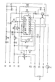
- the electronic energy controller is shown in the drawing using an exemplary embodiment.
- the neutral conductor of the network is at terminal N 1.
- integrated circuit 1 receives the network frequency at a connection 1.6 of a synchronization input for synchronizing and clocking the time sequences.
- the integrated circuit 1 is thus constantly energized, so that it is constantly on standby for its function of the switching operations described below, which it enables.
- the integrated circuit 1 detects the operating state ON or OFF via the power switch 2, which connects the terminal P 1.1 of the heating element to the phase P 1 of the network and applies the resistor R 1 to voltage.
- the desired heating output is set via the center tap of a potentiometer R 3, which is coupled to the power switch 2 in a rotationally locking manner.
- the potentiometer R 3 is connected to the power supply of the integrated circuit 1 at the terminal 1.16.
- a thyristor T 2 is driven via the resistor R 9, which excites the coil circuit of a relay 5 which acts as a load switching element.
- the excitation energy of relay 5 is limited by resistor R 10, rectified by thyristor T 2 and smoothed by capacitor C 2.
- the heating element 3 is connected with its terminal N 2 to the neutral conductor of the network, and a signal circuit can also be switched via the terminals P 2 and P 2.1 of the mains switch 2.
- a hot indicator is connected to the integrated circuit 1 via the resistors R 6 and R 7 and the thyristor T 1, whereby a signal lamp located between the terminal H 1 and the phase of the network is controlled.
- the resistors R 6 and R 7 serve as control resistors, namely R 6 in the case of the 0 state and R 7 in the case of the L state at the output 1.11 of the integrated circuit 1.
- the integrated circuit 1 can be connected to zero potential at its input 1.5 via a time switch 4, as a result of which the power controller function is blocked. This makes it possible to carry out fully automatic, time-dependent cooking processes which run automatically at a given time after the mains switch 2 has been switched on and the time switch 4 has been set. Since the switching of the load current is also taken over by the load switching element 5 of the circuit, only a low-voltage or semiconductor switch is required in the time switch 4. The output power of a digital clock IC is also sufficient for time-dependent signaling.
- potentiometer R 3 While the potentiometer R 3 has one resistance end connected to the supply voltage input 1.16 of the integrated circuit 1, its other resistance end is connected to another input 1.3 of the integrated circuit 1. If the control circuit of the circuit malfunctions, e.g. Interruption, signals are thus supplied to the integrated circuit 1, as a result of which the thyristor T 1 is set in a running on-off state, so that the signal lamp of the so-called hot display is switched to a flashing mode. With this signal, the output power of the circuit is simultaneously reduced to the minimum, e.g. 3% down. In this way, faults that occur are easily recognized and adverse effects on the cooking device are avoided.
- the control circuit of the circuit malfunctions, e.g. Interruption, signals are thus supplied to the integrated circuit 1, as a result of which the thyristor T 1 is set in a running on-off state, so that the signal lamp of the so-called hot display is switched to a flashing mode. With this signal, the output power of the
- the integrated circuit 1 depending on the duty cycle, which can be set manually by means of the potentiometer R 3, can be used to digitally switch an automatic heating period associated with the respectively set duty cycle.
- the residual heat present in the heating element 3 is automatically taken into account if this was previously switched on for a cooking process.
- the integrated circuit 1 is designed so that its output signal has a clock cycle of 30 seconds. This corresponds to an optimal time ratio for switching on cooktops heated with radiant heaters, eg glass ceramic cooktops. In the case of radiators with low inertia, this makes it possible to switch constant temperatures in the power levels set in each case and the service life of the power switching element 5 which switches the power adapted a cooker life provided.
- the integrated circuit is designed in such a way that a minimum heating-up period of 1 minute is maintained in every switch-on position of the energy controller. During this time, only a change in the duty cycle is possible. This changed setting only takes effect after this time has elapsed, in that the heating period and continued cooking power assigned to the changed duty cycle are then set. After the minimum heating period of 1 min has elapsed, the heating period set can be switched off by adjusting the potentiometer R 3 in the direction of lower heating power and switched on again in the direction of higher heating power.
- the integrated circuit 1 is designed so that it has a temperature resistance up to max. 125 0 . Furthermore, it is characterized by its special design for its extremely versatile control processes due to its minimal size.
Landscapes
- Engineering & Computer Science (AREA)
- Chemical & Material Sciences (AREA)
- Combustion & Propulsion (AREA)
- Mechanical Engineering (AREA)
- General Engineering & Computer Science (AREA)
- Food Science & Technology (AREA)
- Physics & Mathematics (AREA)
- General Physics & Mathematics (AREA)
- Automation & Control Theory (AREA)
- Control Of Resistance Heating (AREA)
- Control Of Temperature (AREA)
Applications Claiming Priority (2)
| Application Number | Priority Date | Filing Date | Title |
|---|---|---|---|
| DE3104837 | 1981-02-11 | ||
| DE19813104837 DE3104837A1 (de) | 1981-02-11 | 1981-02-11 | Elektrtonischer energiesteller mit anheizautomatik zur steuerung der heizleistung eines elektrischen heizelementes |
Publications (2)
| Publication Number | Publication Date |
|---|---|
| EP0057902A2 true EP0057902A2 (fr) | 1982-08-18 |
| EP0057902A3 EP0057902A3 (fr) | 1984-02-22 |
Family
ID=6124570
Family Applications (1)
| Application Number | Title | Priority Date | Filing Date |
|---|---|---|---|
| EP82100754A Withdrawn EP0057902A3 (fr) | 1981-02-11 | 1982-02-03 | Régulateur d'énergie électronique avec chauffage automatique pour commander la capacité de chauffe d'un élément de chauffage électrique |
Country Status (2)
| Country | Link |
|---|---|
| EP (1) | EP0057902A3 (fr) |
| DE (1) | DE3104837A1 (fr) |
Cited By (2)
| Publication number | Priority date | Publication date | Assignee | Title |
|---|---|---|---|---|
| AT390536B (de) * | 1986-02-11 | 1990-05-25 | Acotronic Elektronische Appara | Schaltung zur verkehrsmessung in waehlaemtern des fernsprechverkehrs |
| FR2739176A1 (fr) * | 1995-09-27 | 1997-03-28 | Seb Sa | Appareil de cuisson d'un produit alimentaire par rayonnement infrarouge |
Families Citing this family (5)
| Publication number | Priority date | Publication date | Assignee | Title |
|---|---|---|---|---|
| DE3240547A1 (de) * | 1982-11-03 | 1984-06-14 | Diehl Gmbh & Co | Schaltungsanordnung zum umschalten der leistungszufuhr zu elektrischen verbrauchern |
| DE8817041U1 (de) * | 1988-07-22 | 1992-02-20 | Bosch-Siemens Hausgeräte GmbH, 8000 München | Schaltungsanordnung für Elektroherde |
| DE4038167B4 (de) * | 1989-12-15 | 2005-10-20 | Bernhard Rall | Anordnung zur Beheizung von flexiblen Matten, Textilien oder dergleichen |
| DE4029181A1 (de) * | 1990-09-14 | 1992-03-19 | Miele & Cie | Beheizung von backoefen |
| DE19941299A1 (de) * | 1999-08-31 | 2001-03-01 | Eckhard Wahl | Steuerung der Wärmeregelung einer Kochplatte am E-Herd mit elektronischem Zeitschaltglied, kombiniert mit Wärmefühler |
Family Cites Families (7)
| Publication number | Priority date | Publication date | Assignee | Title |
|---|---|---|---|---|
| BE757721A (fr) * | 1969-10-27 | 1971-04-01 | Telemecanique Electrique | Dispositif electrique de mesure et de regulation de la temperature |
| US3873853A (en) * | 1973-08-09 | 1975-03-25 | Rca Corp | Comparator-keyed oscillator |
| US3982098A (en) * | 1974-12-23 | 1976-09-21 | Trostler Richard M | Heater and control system |
| DE2549535B2 (de) * | 1975-11-05 | 1980-05-29 | Brown, Boveri & Cie Ag, 6800 Mannheim | Elektronischer Leistungssteiler |
| FR2385135A1 (fr) * | 1977-03-25 | 1978-10-20 | Radiotechnique Compelec | Programmateur journalier, notamment pour economie d'energie par modulation de chauffage |
| JPS54138978A (en) * | 1978-04-20 | 1979-10-27 | Matsushita Electric Ind Co Ltd | Temperature controller |
| US4222037A (en) * | 1978-12-05 | 1980-09-09 | General Electric Company | Cooking cycle timer |
-
1981
- 1981-02-11 DE DE19813104837 patent/DE3104837A1/de not_active Withdrawn
-
1982
- 1982-02-03 EP EP82100754A patent/EP0057902A3/fr not_active Withdrawn
Cited By (2)
| Publication number | Priority date | Publication date | Assignee | Title |
|---|---|---|---|---|
| AT390536B (de) * | 1986-02-11 | 1990-05-25 | Acotronic Elektronische Appara | Schaltung zur verkehrsmessung in waehlaemtern des fernsprechverkehrs |
| FR2739176A1 (fr) * | 1995-09-27 | 1997-03-28 | Seb Sa | Appareil de cuisson d'un produit alimentaire par rayonnement infrarouge |
Also Published As
| Publication number | Publication date |
|---|---|
| EP0057902A3 (fr) | 1984-02-22 |
| DE3104837A1 (de) | 1982-08-26 |
Similar Documents
| Publication | Publication Date | Title |
|---|---|---|
| DE69832329T2 (de) | Verfahren und Vorrichtung zur Regelung eines elektrischen Heizelementes | |
| DE4022846C2 (de) | Vorrichtung zur Leistungssteuerung und -begrenzung bei einer Heizfläche aus Glaskeramik oder einem vergleichbaren Material | |
| DE2836882C2 (de) | Steuergerät für Elektrokochplatten | |
| EP1838137B1 (fr) | Procédé et circuit destinés à la commande d'au moins un élément de chauffe d'un appareil de chauffage | |
| EP0213442B1 (fr) | Disposition pour commander des fours à micro-ondes et/ou à énergie calorifique | |
| EP0057902A2 (fr) | Régulateur d'énergie électronique avec chauffage automatique pour commander la capacité de chauffe d'un élément de chauffage électrique | |
| EP0789504A2 (fr) | Dispositif de mesure de la température pour le circuit de contrÔle d'un radiateur électrique | |
| EP0828406B1 (fr) | Dispositif pour limiter et distribuer la puissance électrique consommée par une cuisinière | |
| EP0031516B1 (fr) | Appareil de commande pour appareils de chauffage électrique | |
| DE4016525A1 (de) | Steuerschaltkreis fuer einen heizer | |
| DE3737712C2 (fr) | ||
| EP0582795B1 (fr) | Configuration de circuit pour appareils électriques de chauffage | |
| US2218778A (en) | Control system for electric cooking ovens | |
| DE4224666C2 (de) | Schaltung eines Strahlungsheizkörpers | |
| DE1941338A1 (de) | Elektrische Schaltung fuer einen selbstreinigenden Ofen | |
| DE1565816B2 (de) | Steuereinrichtung zum kochen braten und backen | |
| DE3108640A1 (de) | Meldeeinrichtung zur anzeige des temperaturzustandes von kochgeraeten | |
| DE3516788A1 (de) | Strahlungsheizeinrichtung fuer kochgeraete, insbesondere fuer glaskeramik-kochmulden | |
| AT393583B (de) | Temperatursteuereinrichtung fuer einen backofen | |
| DE3908242A1 (de) | Heizeinrichtung | |
| DE4407741A1 (de) | Sensorschalter-Einrichtung zum Ein- und Ausschalten eines elektrischen Verbrauchers | |
| DE19620567A1 (de) | Regelelektronik mit einem Strahlungsheizkörper | |
| DE2348154C3 (fr) | ||
| DE19820562A1 (de) | Gargerät | |
| DE102019216955A1 (de) | Gargerätesteuerung mit Betriebsartenschalter und Schaltuhr |
Legal Events
| Date | Code | Title | Description |
|---|---|---|---|
| PUAI | Public reference made under article 153(3) epc to a published international application that has entered the european phase |
Free format text: ORIGINAL CODE: 0009012 |
|
| AK | Designated contracting states |
Designated state(s): AT CH FR GB IT SE |
|
| PUAL | Search report despatched |
Free format text: ORIGINAL CODE: 0009013 |
|
| AK | Designated contracting states |
Designated state(s): AT CH FR GB IT LI SE |
|
| 17P | Request for examination filed |
Effective date: 19840803 |
|
| STAA | Information on the status of an ep patent application or granted ep patent |
Free format text: STATUS: THE APPLICATION IS DEEMED TO BE WITHDRAWN |
|
| 18D | Application deemed to be withdrawn |
Effective date: 19860831 |
|
| RIN1 | Information on inventor provided before grant (corrected) |
Inventor name: THORWEST, JOACHIM, ING.GRAD. Inventor name: ZAPP, ROBERT, ING.GRAD. |