EP0058039B1 - Gyrotron - Google Patents
Gyrotron Download PDFInfo
- Publication number
- EP0058039B1 EP0058039B1 EP82300526A EP82300526A EP0058039B1 EP 0058039 B1 EP0058039 B1 EP 0058039B1 EP 82300526 A EP82300526 A EP 82300526A EP 82300526 A EP82300526 A EP 82300526A EP 0058039 B1 EP0058039 B1 EP 0058039B1
- Authority
- EP
- European Patent Office
- Prior art keywords
- electrons
- waveguide
- axis
- magnetic field
- gyrotron
- Prior art date
- Legal status (The legal status is an assumption and is not a legal conclusion. Google has not performed a legal analysis and makes no representation as to the accuracy of the status listed.)
- Expired
Links
- 238000010894 electron beam technology Methods 0.000 claims description 7
- 238000002347 injection Methods 0.000 claims description 6
- 239000007924 injection Substances 0.000 claims description 6
- 230000001154 acute effect Effects 0.000 claims 1
- 230000005684 electric field Effects 0.000 description 7
- 230000003993 interaction Effects 0.000 description 5
- 230000007423 decrease Effects 0.000 description 4
- 230000000979 retarding effect Effects 0.000 description 2
- 230000001419 dependent effect Effects 0.000 description 1
- 230000004048 modification Effects 0.000 description 1
- 238000012986 modification Methods 0.000 description 1
- 239000003607 modifier Substances 0.000 description 1
- 230000007704 transition Effects 0.000 description 1
Images
Classifications
-
- H—ELECTRICITY
- H01—ELECTRIC ELEMENTS
- H01J—ELECTRIC DISCHARGE TUBES OR DISCHARGE LAMPS
- H01J23/00—Details of transit-time tubes of the types covered by group H01J25/00
- H01J23/02—Electrodes; Magnetic control means; Screens
- H01J23/06—Electron or ion guns
- H01J23/07—Electron or ion guns producing a hollow cylindrical beam
-
- H—ELECTRICITY
- H01—ELECTRIC ELEMENTS
- H01J—ELECTRIC DISCHARGE TUBES OR DISCHARGE LAMPS
- H01J25/00—Transit-time tubes, e.g. klystrons, travelling-wave tubes, magnetrons
- H01J25/02—Tubes with electron stream modulated in velocity or density in a modulator zone and thereafter giving up energy in an inducing zone, the zones being associated with one or more resonators
- H01J25/025—Tubes with electron stream modulated in velocity or density in a modulator zone and thereafter giving up energy in an inducing zone, the zones being associated with one or more resonators with an electron stream following a helical path
Definitions
- the present invention relates to a gyrotron device, for example a gyrotron amplifier or a gyrotron oscillator.
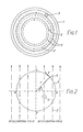
- a conventional gyrotron device comprises a circular waveguide 1 dimensioned to operate in the TE o1 mode at a chosen RF frequency.
- the TE o1 mode electric field is shown by dashed lines 2 in Figure 1.
- An axial magnetic field 3 of strength B is applied to the waveguide and a hollow electron beam, the inner and outer bounds of which are indicated by thick lines 4, is passed along the waveguide.
- an individual electron 6 is caused to gyrate under the influence of the magnetic field.
- e is the electronic charge
- B is the magnetic field strength
- m the relativistic mass of the electron.
- the radius of the orbit is given by where v is the tangential velocity of the electron.
- ⁇ o is the angular r.f. frequency.
- ⁇ c the angular frequency of the electron, ⁇ c , is equal to the angular frequency of the applied r.f. field ⁇ o , then the electron that started at A will now be at B, and once again experiencing a retarding field, whereas the electron that started at B will now be at A and once again experiencing and acclerating field.
- electrons in the beam have, at least when they are initially in the waveguide, many different phases relative to the RF field.
- Electrons in this sector will therefore advance in phase, moving cycle by cycle, towards point C. Also from equation (ii), as the electron's mass and velocity decreases, so its radius of gyration will decrease.
- the cyclotron frequency ⁇ c is slightly less than the angular RF frequency ⁇ o , e.g. and the phase of the bunched electrons relative to the field is adjusted so that the electrons give up nett energy to the RF field in excess of cavity losses so output power is available.
- the output power is dependent on the numbers of electrons bunched in the appropriate phase to give up energy to the RF field.
- a gyrotron oscillator comprising,
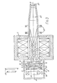
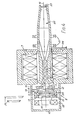
- FIG. 3 which shows a gyrotron oscillator the circular waveguide 1, defines an interaction region which is dimensioned as a resonant cavity to operate in the fundamental TE o , mode at the desired RF frequency ⁇ o whereby a standing wave is set up in the cavity.
- the axial magnetic field of strength B is produced by a solenoid 7 surrounding the waveguide.
- the hollow electron beam 4 is produced by injection means 8.
- the means 8 comprises an annular thermionic cathode, of triangular cross-section, coaxial with the axis 10 of the waveguide 1, the cathode 9 having a flat annular emissive surface 11 facing the axis 10, the normal 12 to the surface 11 having an angle of incidence a to the axis.
- An annular heater 13 is provided for the cathode 9.
- a control grid 14 is annular and spaced from, and parallel to, the emissive surface 11 of the cathode, being in the form of a truncated hollow cone having many apertures 15 in it for the passage of electrons therethrough.
- An annular anode 16 having apertures 17 in it for the electrons is also provided.
- the electrons in the beam are constrained to follow the normal 12 by producing a magnetic field directed parallel to the normal 12.
- This field is produced by modifying the lines of force of the magnetic field of the solenoid using some form of magnetic field modifier.
- an annular magnetic coil 18 on that side of the cathode 9 remote from the solenoid is used.
- the modification produces a magnetic field which is as nearly parallel to the normal 12 as possible with an abrupt transition to parallel to the axis 10.
- an additional annular electrode is provided on the grid 14.
- This additional electrode may take the form of two annular wires 19 positioned at the respective sides of the grid 14. Each wire may be replaced by an annular electrode having a humped cross-section as shown at 20.
- the potentials applied to the cathode 9, the control grid 14, the additional electrode 19 or 20 and the anode 16 are chosen to produce a beam having a desired beam current and a desired beam velocity.
- the beam velocity and angle ⁇ of incidence to the axis 10 is chosen so that: the component of velocity normal to the axis produces gyration of the electrons in the beam at the cyclotron frequency, required for interaction with the RF field of frequency co o ; and
- the component of velocity parallel to the axis is such that a plurality of complete cycles of the gyrating beam exist in the interaction region.
- the interaction region is dimensioned as a resonant cavity supporting an RF standing wave at the desired frequency ⁇ o .
- the electron beam forms a standing wave in the cavity which in turn generates an RF standing wave, at the frequency ⁇ o .
- the electron beam passes along the waveguide 1 it progressively interacts with, and gives up energy to, the RF field.
- the beam is finally diverged by magnetic coils 21 into the collector region in the output waveguide 22 which is sealed by a window 23.
- the interaction region is dimensioned so as not to resonate at the frequency ⁇ o and, as shown in Figure 4, a waveguide feed 24 is provided to introduce RF energy, of frequency ⁇ o , into the cavity.
- the amplifier and oscillator are identical.
Landscapes
- Microwave Tubes (AREA)
Claims (5)
Applications Claiming Priority (2)
| Application Number | Priority Date | Filing Date | Title |
|---|---|---|---|
| GB8104066 | 1981-02-10 | ||
| GB8104066 | 1981-02-10 |
Publications (3)
| Publication Number | Publication Date |
|---|---|
| EP0058039A2 EP0058039A2 (fr) | 1982-08-18 |
| EP0058039A3 EP0058039A3 (en) | 1982-09-08 |
| EP0058039B1 true EP0058039B1 (fr) | 1985-02-20 |
Family
ID=10519586
Family Applications (1)
| Application Number | Title | Priority Date | Filing Date |
|---|---|---|---|
| EP82300526A Expired EP0058039B1 (fr) | 1981-02-10 | 1982-02-02 | Gyrotron |
Country Status (3)
| Country | Link |
|---|---|
| US (1) | US4482843A (fr) |
| EP (1) | EP0058039B1 (fr) |
| DE (1) | DE3262358D1 (fr) |
Families Citing this family (11)
| Publication number | Priority date | Publication date | Assignee | Title |
|---|---|---|---|---|
| GB2096392B (en) * | 1981-04-06 | 1985-04-03 | Varian Associates | Collector-output for hollow beam electron tubes |
| GB2109986A (en) * | 1981-11-13 | 1983-06-08 | Emi Varian Ltd | Gyro amplifier |
| US4562380A (en) * | 1983-06-13 | 1985-12-31 | Raytheon Company | Tilt-angle electron gun |
| US4621219A (en) * | 1984-07-17 | 1986-11-04 | Varian Associates, Inc. | Electron beam scrambler |
| US4897609A (en) * | 1987-12-28 | 1990-01-30 | Raytheon Company | Axially coupled gyrotron and gyro TWTA |
| JPH0642568B2 (ja) * | 1989-07-13 | 1994-06-01 | 住友重機械工業株式会社 | シンクロトロン放射光励起レーザ装置 |
| JP3444999B2 (ja) * | 1994-03-17 | 2003-09-08 | 三菱電機株式会社 | ジャイロトロン装置 |
| JPH09223850A (ja) * | 1996-02-19 | 1997-08-26 | Kagaku Gijutsu Shinko Jigyodan | スーパーハードレーザーの発生方法及びその装置 |
| FR2756970B1 (fr) * | 1996-12-10 | 2003-03-07 | Thomson Tubes Electroniques | Tube hyperfrequence a interaction longitudinale a cavite a sortie au dela du collecteur |
| US8642959B2 (en) * | 2007-10-29 | 2014-02-04 | Micron Technology, Inc. | Method and system of performing three-dimensional imaging using an electron microscope |
| US9520263B2 (en) | 2013-02-11 | 2016-12-13 | Novaray Medical Inc. | Method and apparatus for generation of a uniform-profile particle beam |
Family Cites Families (7)
| Publication number | Priority date | Publication date | Assignee | Title |
|---|---|---|---|---|
| US2812467A (en) * | 1952-10-10 | 1957-11-05 | Bell Telephone Labor Inc | Electron beam system |
| NL275577A (fr) * | 1961-03-06 | |||
| US3315110A (en) * | 1963-08-12 | 1967-04-18 | Sperry Rand Corp | Shaped-field hollow beam electron gun having high beam perveance and high beam convergence ratio |
| US3631315A (en) * | 1969-10-20 | 1971-12-28 | Raytheon Co | Broadband traveling wave device having a logarithmically varying bidimensional interaction space |
| FR2401508A1 (fr) * | 1977-06-27 | 1979-03-23 | Commissariat Energie Atomique | Injecteur d'electrons pour generateur hyperfrequence |
| US4224576A (en) * | 1978-09-19 | 1980-09-23 | The United States Of America As Represented By The Secretary Of The Navy | Gyrotron travelling-wave amplifier |
| US4393332A (en) * | 1980-09-05 | 1983-07-12 | Varian Associates, Inc. | Gyrotron transverse energy equalizer |
-
1982
- 1982-02-02 DE DE8282300526T patent/DE3262358D1/de not_active Expired
- 1982-02-02 EP EP82300526A patent/EP0058039B1/fr not_active Expired
- 1982-02-05 US US06/346,201 patent/US4482843A/en not_active Expired - Fee Related
Also Published As
| Publication number | Publication date |
|---|---|
| EP0058039A3 (en) | 1982-09-08 |
| EP0058039A2 (fr) | 1982-08-18 |
| US4482843A (en) | 1984-11-13 |
| DE3262358D1 (de) | 1985-03-28 |
Similar Documents
| Publication | Publication Date | Title |
|---|---|---|
| EP0058039B1 (fr) | Gyrotron | |
| EP0934599B1 (fr) | Collecteur multi-etage deprime pour gyrotrons a petite orbite | |
| JP3121157B2 (ja) | マイクロトロン電子加速器 | |
| US4345220A (en) | High power microwave generator using relativistic electron beam in waveguide drift tube | |
| US2591350A (en) | Traveling-wave electron reaction device | |
| US4199709A (en) | Injection of an electron beam | |
| US4370621A (en) | High efficiency gyrotron oscillator and amplifier | |
| EP0475199B1 (fr) | Source pour la production d'un faisceau d'atomer rapides | |
| US3450931A (en) | Cyclotron motion linear accelerator | |
| US4571524A (en) | Electron accelerator and a millimeter-wave and submillimeter-wave generator equipped with said accelerator | |
| US4621219A (en) | Electron beam scrambler | |
| US5440211A (en) | Electron accelerator having a coaxial cavity | |
| EP3488668B1 (fr) | Appareil de production d'ondes électromagnétiques | |
| CA1053312A (fr) | Dispositif de concentration d'un faisceau de particules chargees accelerees par un cyclotron | |
| US20020060521A1 (en) | Apparatus for bunching relativistic electrons | |
| US2593845A (en) | Apparatus for the acceleration of electrons | |
| Akimov et al. | High-power X-band pulse magnicon | |
| JP2569812B2 (ja) | 高エネルギイオン注入装置 | |
| US2931903A (en) | Acceleration and application of high intensity electron beams for radiation processing | |
| GB2109986A (en) | Gyro amplifier | |
| US2853645A (en) | Electron concentrating and energy transducing device | |
| JPH0697640B2 (ja) | 高周波四重極加速器における加速エネルギ制御方法 | |
| EP0367155A2 (fr) | Oscillateur à hautes fréquences | |
| JP3027822B2 (ja) | 荷電粒子ビームのマイクロバンチング方法及びそのための装置 | |
| US4520293A (en) | High frequency amplifier |
Legal Events
| Date | Code | Title | Description |
|---|---|---|---|
| PUAI | Public reference made under article 153(3) epc to a published international application that has entered the european phase |
Free format text: ORIGINAL CODE: 0009012 |
|
| PUAL | Search report despatched |
Free format text: ORIGINAL CODE: 0009013 |
|
| AK | Designated contracting states |
Designated state(s): DE FR GB |
|
| AK | Designated contracting states |
Designated state(s): DE FR GB |
|
| 17P | Request for examination filed |
Effective date: 19821018 |
|
| GRAA | (expected) grant |
Free format text: ORIGINAL CODE: 0009210 |
|
| AK | Designated contracting states |
Designated state(s): DE FR GB |
|
| REF | Corresponds to: |
Ref document number: 3262358 Country of ref document: DE Date of ref document: 19850328 |
|
| ET | Fr: translation filed | ||
| PLBE | No opposition filed within time limit |
Free format text: ORIGINAL CODE: 0009261 |
|
| STAA | Information on the status of an ep patent application or granted ep patent |
Free format text: STATUS: NO OPPOSITION FILED WITHIN TIME LIMIT |
|
| 26N | No opposition filed | ||
| PG25 | Lapsed in a contracting state [announced via postgrant information from national office to epo] |
Ref country code: DE Effective date: 19871103 |
|
| GBPC | Gb: european patent ceased through non-payment of renewal fee | ||
| PG25 | Lapsed in a contracting state [announced via postgrant information from national office to epo] |
Ref country code: FR Free format text: LAPSE BECAUSE OF NON-PAYMENT OF DUE FEES Effective date: 19881028 |
|
| PG25 | Lapsed in a contracting state [announced via postgrant information from national office to epo] |
Ref country code: GB Free format text: LAPSE BECAUSE OF NON-PAYMENT OF DUE FEES Effective date: 19881121 |
|
| REG | Reference to a national code |
Ref country code: FR Ref legal event code: ST |