EP0058050A1 - Procédé de mesure de fréquence - Google Patents
Procédé de mesure de fréquence Download PDFInfo
- Publication number
- EP0058050A1 EP0058050A1 EP82300552A EP82300552A EP0058050A1 EP 0058050 A1 EP0058050 A1 EP 0058050A1 EP 82300552 A EP82300552 A EP 82300552A EP 82300552 A EP82300552 A EP 82300552A EP 0058050 A1 EP0058050 A1 EP 0058050A1
- Authority
- EP
- European Patent Office
- Prior art keywords
- frequency
- input
- circuit
- sampling
- detection system
- Prior art date
- Legal status (The legal status is an assumption and is not a legal conclusion. Google has not performed a legal analysis and makes no representation as to the accuracy of the status listed.)
- Granted
Links
Images

Classifications
-
- G—PHYSICS
- G01—MEASURING; TESTING
- G01R—MEASURING ELECTRIC VARIABLES; MEASURING MAGNETIC VARIABLES
- G01R23/00—Arrangements for measuring frequencies; Arrangements for analysing frequency spectra
- G01R23/02—Arrangements for measuring frequency, e.g. pulse repetition rate; Arrangements for measuring period of current or voltage
Definitions
- This invention relates to a frequency detection system for detecting the frequencycf for example, an electric power system by digitally processing an electrical quantity, for example a voltage magnitude thereof.
- a conventional frequency detection system counts pulses during half cycles of the a.c. in an electric power system, and compares the count with a frequency in a binary form set in a setting circuit to determine whether the frequency of the electric power system is higher or lower than that set in the setting circuit. Such a system is not able to detect the absolute value of the frequency.
- an AC input having a frequency to be detected is sampled with a predetermined constant sampling period to form four consecutive samples from which is calculated a quantity dependent only on and constituting a measure of the frequency.
- the present invention provides a frequency detection system comprising sampling means for sampling an AC input V(t) having a frequency to be detected, with a predetermined constant sampling period h to form sampled values V(t 0 - 2h), V(t 0 - h), V(t o + h) and V(t 0 + 2h) where to designates any desired time point, and calculating means for calculating to provide a measure of the frequency of the AC input.
- the frequency detection system comprises another calculating means for calculating an arccosine function of y(h) so as to determine the absolute value of the frequency of the AC input.
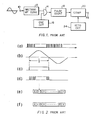
- Figure 1 shows a conventional frequency detection system.
- the arrangement illustrated comprises an AC input terminal 10, a rectangular waveform converter circuit 12 connected to the input terminal 10, and an "AND" circuit 14 with one input connected to the output of rectangular waveform converter circuit 12, the other input connected to the output of an oscillation circuit 16, and an output connected to a binary counter 18.
- the binary counter 18 is connected to one input of a comparator circuit 20 with an output terminal 22.
- the comparator circuit 20 has another input connected to a setting circuit 24 in which is set a binary number representing a predetermined frequency with which the frequency of the AC input is to be compared.
- the rectangular waveform converter circuit 12 receives via the input terminal 10 an AC input represented by the sinusoidal wave (b) in Figure 2, having a period T.
- the AC input is also shown beside the input terminal 10 in Figure 1 as a sinusoidal wave.
- the converter circuit 12 converts the'positive half cycle of the AC input to a rectangular waveform having a duration equal to T/2 namely the direction of the positive half cycle, as shown at waveform (c) in Figure 2.
- That rectangular waveform (c) is applied to one input of the "AND" circuit 14, whose other input receives a train of rectangular pulses from the oscillation circuit 16 at a much higher frequency than the AC input.
- the train of rectangular pulses generated by the oscillation circuit 16 has a predetermined pulse repection frequency, as shown at waveform (a) in Figure 2.
- the "AND" circuit 14 forms the logical sum of the rectangular waveform from the converter circuit 12 and rectangular pulses from the oscillator circuit 16 and delivers to the binary counter 18 a pulse sequence as shown at waveform (d) in Figure 2, comprising a number of pulses dependent on the duration T/2 and therefore on the AC frequency.
- the binary counter 18 counts the pulses included in the pulse sequence applied thereto and supplied its count in binary form to the comparator circuit 20.
- the count from the counter 18 is shown at (e) as being a binary number (1001......01).
- the setting circuit 24 contains a binary value set to represent that frequency with which the actual frequency of the AC input is to be compared.
- the set value is a binary number (1101 /01) as shown at (f) in Figure 2.
- the comparator circuit 20 compares the count from the binary counter 18 with the set reference value from the setting circuit 24 to determine which of the two is larger.
- n designates the set value from the setting circuit 24 and 4f designates the pulse repetition frequency of the pulses generated by the oscillation circuit 16
- the frequency f of the AC input may be expressed by
- the comparator circuit 20 can determine whether the frequency of the AC input is larger or smaller than the set value from the setting circuit 24.
- the frequency of the AC input is higher than the set value as will readily be understood from the binary numbers shown at the rows
- Figure 3 shows the manner in which the AC input is sampled in accordance with the present invention while Figure 4 is a block diagram of an embodiment of the present invention.
- the uppermost portion (a) shows an AC input in the form of a sinusoidal wave having a frequency to be determined
- the intermediate portion (b) shows sampling positions disposed at predetermined equal intervals h along the time axis t
- the lowest portion (c) shows values of the AC input sampled at the sampling positions.
- V(t) is expressed by where V designates the peak value of the AC input and designates the angular frequency thereof.
- the AC input is sampled at time points t - 2h, t - h, t + h and t o + 2h respectively where t o designates any desired time point.
- the sampled values may be expressed by and respectively.
- the sampled values are used to form quantity y(h) defined as: therefore:
- Figure 4 shows one embodiment of the frequency detection system of the present invention, for effecting the sampling and calculations as described above.
- the arrangement illustrated comprises an analog filter 40, a sampling and holding circuit 42 and an analog-to digital converter circuit 44 serially interconnected in the named order.
- An AC input such as shown at waveform (a) in Figure 3 is passed through the analog filter 40 which eliminates folding error from the sampling and holding circuit 42 and is then sampled with the sampling period h to form sampled values V(t - 2h), V(t o - h), V(t o + h) and V(t o + 2h) as described above in conjunction with Figure 3.
- the converted digital values are supplied to an input circuit 46 forming a computer with a calculating circuit 48 and an output circuit 50 connected in series with each other.
- the calculating circuit 48 receives the digital values through the input circuit 46 and uses them to effect calculations in accordance with the above expressions (5) and (6) to detect or determine the frequency of the AC input. The frequency thus detected or determined is delivered via the output circuit 50 to an output connected to the latter.
- the components 42, 44, 46, 48 and 50 are connected to a control circuit 52 to be controlled thereby.
Landscapes
- Physics & Mathematics (AREA)
- General Physics & Mathematics (AREA)
- Measuring Frequencies, Analyzing Spectra (AREA)
Applications Claiming Priority (2)
| Application Number | Priority Date | Filing Date | Title |
|---|---|---|---|
| JP56018609A JPS57133362A (en) | 1981-02-10 | 1981-02-10 | Frequency detector |
| JP18609/81 | 1981-02-10 |
Publications (2)
| Publication Number | Publication Date |
|---|---|
| EP0058050A1 true EP0058050A1 (fr) | 1982-08-18 |
| EP0058050B1 EP0058050B1 (fr) | 1985-05-15 |
Family
ID=11976374
Family Applications (1)
| Application Number | Title | Priority Date | Filing Date |
|---|---|---|---|
| EP82300552A Expired EP0058050B1 (fr) | 1981-02-10 | 1982-02-03 | Procédé de mesure de fréquence |
Country Status (4)
| Country | Link |
|---|---|
| US (1) | US4437057A (fr) |
| EP (1) | EP0058050B1 (fr) |
| JP (1) | JPS57133362A (fr) |
| DE (1) | DE3263464D1 (fr) |
Cited By (8)
| Publication number | Priority date | Publication date | Assignee | Title |
|---|---|---|---|---|
| FR2535462A1 (fr) * | 1982-10-29 | 1984-05-04 | Labo Electronique Physique | Circuit numerique de mesure de la frequence instantanee d'un signal module ou non en frequence, ainsi que recepteur de television ou de radio equipe d'un tel circuit |
| GB2144288A (en) * | 1983-07-29 | 1985-02-27 | Rca Corp | Method and apparatus for fm demodulation |
| US4633516A (en) * | 1985-05-30 | 1986-12-30 | United States Of America As Represented By The Secretary Of The Air Force | Instantaneous frequency measurement receiver with digital processing |
| US4910469A (en) * | 1989-05-02 | 1990-03-20 | Rca Licensing Corporation | Demodulator for sampled data FM signals |
| EP0392582A1 (fr) * | 1989-04-03 | 1990-10-17 | Koninklijke Philips Electronics N.V. | Procédé de différenciation de fréquences |
| EP0373802A3 (fr) * | 1988-12-10 | 1991-05-29 | THORN EMI plc | Mesure de fréquence |
| EP0638811A3 (fr) * | 1993-08-12 | 1996-04-10 | Rockwell International Corp | Dispositif d'estimation de l'amplitude et de la fréquence d'un signal sinusoidal bruité et polarisé à partir de brefs paquets d'échantillons. |
| US10296305B2 (en) | 2013-09-27 | 2019-05-21 | Rudolf Markus PETRI | Method and device for the automated production and provision of at least one software application |
Families Citing this family (3)
| Publication number | Priority date | Publication date | Assignee | Title |
|---|---|---|---|---|
| JP2520713B2 (ja) * | 1988-11-05 | 1996-07-31 | 三菱電機株式会社 | デジタル保護継電器 |
| JP3119541B2 (ja) * | 1993-03-25 | 2000-12-25 | 株式会社東芝 | 周波数検出方式 |
| SE512369C2 (sv) | 1998-07-03 | 2000-03-06 | Foersvarets Forskningsanstalt | Sätt att mäta frekvensen hos en sinusformad signal |
Family Cites Families (4)
| Publication number | Priority date | Publication date | Assignee | Title |
|---|---|---|---|---|
| US2280524A (en) | 1940-11-01 | 1942-04-21 | Gen Electric | Electrical wave analysis |
| US2995727A (en) | 1957-10-29 | 1961-08-08 | Ibm | Means for comparing wave shapes |
| US3454876A (en) | 1967-03-02 | 1969-07-08 | Teledyne Ind | Spectral analysis of events of finite record length |
| JPS5112166A (ja) * | 1974-07-22 | 1976-01-30 | Tokyo Electric Power Co | Shuhasukenshutsuhoshiki |
-
1981
- 1981-02-10 JP JP56018609A patent/JPS57133362A/ja active Pending
-
1982
- 1982-01-26 US US06/342,917 patent/US4437057A/en not_active Expired - Lifetime
- 1982-02-03 DE DE8282300552T patent/DE3263464D1/de not_active Expired
- 1982-02-03 EP EP82300552A patent/EP0058050B1/fr not_active Expired
Non-Patent Citations (2)
| Title |
|---|
| Electronics Letters, Vol. 14, No. 12, June 1978, Hitchin M.J. UNDERHILL et al. "Fast-Sampling Frequency Meter" pages 366, 367 * complete article * * |
| Frequenz, Vol. 27, No. 11, 1973 Berlin K.-H. JUTZI "Frequenzbestimmung durch Signalabtastung" pages 309 to 311 * complete article * * |
Cited By (10)
| Publication number | Priority date | Publication date | Assignee | Title |
|---|---|---|---|---|
| FR2535462A1 (fr) * | 1982-10-29 | 1984-05-04 | Labo Electronique Physique | Circuit numerique de mesure de la frequence instantanee d'un signal module ou non en frequence, ainsi que recepteur de television ou de radio equipe d'un tel circuit |
| EP0107884A1 (fr) * | 1982-10-29 | 1984-05-09 | Laboratoires D'electronique Et De Physique Appliquee L.E.P. | Circuit numérique de mesure de la fréquence instantanée d'un signal modulé ou non en fréquence, ainsi que récepteur de télévision ou de radio équipé d'un tel circuit |
| GB2144288A (en) * | 1983-07-29 | 1985-02-27 | Rca Corp | Method and apparatus for fm demodulation |
| US4547737A (en) * | 1983-07-29 | 1985-10-15 | Rca Corporation | Demodulator of sampled data FM signals from sets of four successive samples |
| US4633516A (en) * | 1985-05-30 | 1986-12-30 | United States Of America As Represented By The Secretary Of The Air Force | Instantaneous frequency measurement receiver with digital processing |
| EP0373802A3 (fr) * | 1988-12-10 | 1991-05-29 | THORN EMI plc | Mesure de fréquence |
| EP0392582A1 (fr) * | 1989-04-03 | 1990-10-17 | Koninklijke Philips Electronics N.V. | Procédé de différenciation de fréquences |
| US4910469A (en) * | 1989-05-02 | 1990-03-20 | Rca Licensing Corporation | Demodulator for sampled data FM signals |
| EP0638811A3 (fr) * | 1993-08-12 | 1996-04-10 | Rockwell International Corp | Dispositif d'estimation de l'amplitude et de la fréquence d'un signal sinusoidal bruité et polarisé à partir de brefs paquets d'échantillons. |
| US10296305B2 (en) | 2013-09-27 | 2019-05-21 | Rudolf Markus PETRI | Method and device for the automated production and provision of at least one software application |
Also Published As
| Publication number | Publication date |
|---|---|
| EP0058050B1 (fr) | 1985-05-15 |
| US4437057A (en) | 1984-03-13 |
| JPS57133362A (en) | 1982-08-18 |
| DE3263464D1 (en) | 1985-06-20 |
Similar Documents
| Publication | Publication Date | Title |
|---|---|---|
| US4356553A (en) | Method for the measuring of electrical power | |
| EP0058050A1 (fr) | Procédé de mesure de fréquence | |
| US4224568A (en) | Frequency to digital converter | |
| US4291377A (en) | Apparatus for measuring electrical power | |
| EP0047090B1 (fr) | Méthode et appareil pour la conversion d'une tension analogique en une représentation numérique | |
| US4006348A (en) | Apparatus for monitoring two electric quantities by combining three consecutive samples of each quantity | |
| US4075697A (en) | Apparatus for monitoring two electric quantities by combining three consecutive samples of each quantity | |
| EP0535124B1 (fr) | Convertisseur analogique-numerique | |
| KR840002376B1 (ko) | 전자식 피상 전력량계 | |
| SU1262399A2 (ru) | Устройство дл измерени амплитуды синусоидального напр жени | |
| SU661378A1 (ru) | Цифровой измеритель мощности | |
| SU1732287A1 (ru) | Способ измерени относительной разности амплитуд двух гармонических напр жений | |
| RU2153679C2 (ru) | Способ комплексного определения параметров переменного напряжения или тока синусоидальной формы | |
| SU999155A1 (ru) | Устройство дл измерени амплитуды высокочастотных сигналов | |
| JPH0629722Y2 (ja) | Ae計測装置 | |
| RU2017161C1 (ru) | Устройство для измерения электрических параметров | |
| US4984469A (en) | Amplitude measurement device for viscoelasticity analysis | |
| SU1190277A1 (ru) | Устройство дл измерени электрических параметров пороговых элементов | |
| SU1486944A1 (ru) | Устройство для индикации отклонения переменного напряжения | |
| SU1651240A1 (ru) | Способ определени параметров экспоненциальных радиоимпульсов и видеоимпульсов и устройство дл его осуществлени | |
| SU1367155A1 (ru) | Аналого-цифровой преобразователь с самоконтролем | |
| SU884910A1 (ru) | Устройство дл автоматического измерени энергии при стыковой сварке | |
| SU1308937A1 (ru) | Устройство дл измерени сопротивлени обмоток электрооборудовани переменного тока | |
| SU851342A1 (ru) | Устройство дл измерени и контрол пАРАМЕТРОВ | |
| SU871087A2 (ru) | Измерительный преобразователь переменного напр жени в посто нное |
Legal Events
| Date | Code | Title | Description |
|---|---|---|---|
| PUAI | Public reference made under article 153(3) epc to a published international application that has entered the european phase |
Free format text: ORIGINAL CODE: 0009012 |
|
| AK | Designated contracting states |
Designated state(s): CH DE GB SE |
|
| 17P | Request for examination filed |
Effective date: 19821104 |
|
| GRAA | (expected) grant |
Free format text: ORIGINAL CODE: 0009210 |
|
| AK | Designated contracting states |
Designated state(s): CH DE GB LI SE |
|
| REF | Corresponds to: |
Ref document number: 3263464 Country of ref document: DE Date of ref document: 19850620 |
|
| PLBE | No opposition filed within time limit |
Free format text: ORIGINAL CODE: 0009261 |
|
| STAA | Information on the status of an ep patent application or granted ep patent |
Free format text: STATUS: NO OPPOSITION FILED WITHIN TIME LIMIT |
|
| 26N | No opposition filed | ||
| EAL | Se: european patent in force in sweden |
Ref document number: 82300552.5 |
|
| PGFP | Annual fee paid to national office [announced via postgrant information from national office to epo] |
Ref country code: GB Payment date: 19960125 Year of fee payment: 15 |
|
| PGFP | Annual fee paid to national office [announced via postgrant information from national office to epo] |
Ref country code: SE Payment date: 19960215 Year of fee payment: 15 Ref country code: DE Payment date: 19960215 Year of fee payment: 15 |
|
| PGFP | Annual fee paid to national office [announced via postgrant information from national office to epo] |
Ref country code: CH Payment date: 19960306 Year of fee payment: 15 |
|
| PG25 | Lapsed in a contracting state [announced via postgrant information from national office to epo] |
Ref country code: GB Effective date: 19970203 |
|
| PG25 | Lapsed in a contracting state [announced via postgrant information from national office to epo] |
Ref country code: SE Effective date: 19970204 |
|
| PG25 | Lapsed in a contracting state [announced via postgrant information from national office to epo] |
Ref country code: LI Effective date: 19970228 Ref country code: CH Effective date: 19970228 |
|
| GBPC | Gb: european patent ceased through non-payment of renewal fee |
Effective date: 19970203 |
|
| REG | Reference to a national code |
Ref country code: CH Ref legal event code: PL |
|
| PG25 | Lapsed in a contracting state [announced via postgrant information from national office to epo] |
Ref country code: DE Effective date: 19971101 |
|
| EUG | Se: european patent has lapsed |
Ref document number: 82300552.5 |