EP0058351B1 - Verbindungsvorrichtung für Wicklungsanfänge und Wicklungsenden der Induktionsmotorläuferwicklung eines elektrischen Motors - Google Patents
Verbindungsvorrichtung für Wicklungsanfänge und Wicklungsenden der Induktionsmotorläuferwicklung eines elektrischen Motors Download PDFInfo
- Publication number
- EP0058351B1 EP0058351B1 EP82100810A EP82100810A EP0058351B1 EP 0058351 B1 EP0058351 B1 EP 0058351B1 EP 82100810 A EP82100810 A EP 82100810A EP 82100810 A EP82100810 A EP 82100810A EP 0058351 B1 EP0058351 B1 EP 0058351B1
- Authority
- EP
- European Patent Office
- Prior art keywords
- winding
- switching ring
- induction motor
- coils
- rotor
- Prior art date
- Legal status (The legal status is an assumption and is not a legal conclusion. Google has not performed a legal analysis and makes no representation as to the accuracy of the status listed.)
- Expired
Links
- 238000004804 winding Methods 0.000 title claims abstract description 147
- 230000006698 induction Effects 0.000 title claims abstract description 30
- 238000003475 lamination Methods 0.000 claims abstract 6
- 239000004020 conductor Substances 0.000 claims abstract 2
- 239000011248 coating agent Substances 0.000 claims description 3
- 238000000576 coating method Methods 0.000 claims description 3
- RYGMFSIKBFXOCR-UHFFFAOYSA-N Copper Chemical compound [Cu] RYGMFSIKBFXOCR-UHFFFAOYSA-N 0.000 claims description 2
- 229910052802 copper Inorganic materials 0.000 claims description 2
- 239000010949 copper Substances 0.000 claims description 2
- 238000004519 manufacturing process Methods 0.000 description 8
- 238000000034 method Methods 0.000 description 6
- 238000010586 diagram Methods 0.000 description 3
- 238000005266 casting Methods 0.000 description 2
- 239000000463 material Substances 0.000 description 2
- 238000003825 pressing Methods 0.000 description 2
- 239000011347 resin Substances 0.000 description 2
- 229920005989 resin Polymers 0.000 description 2
- 229910000679 solder Inorganic materials 0.000 description 2
- 230000002411 adverse Effects 0.000 description 1
- 230000001427 coherent effect Effects 0.000 description 1
- 150000001875 compounds Chemical class 0.000 description 1
- 238000009826 distribution Methods 0.000 description 1
- 238000005516 engineering process Methods 0.000 description 1
- 230000002349 favourable effect Effects 0.000 description 1
- 238000002347 injection Methods 0.000 description 1
- 239000007924 injection Substances 0.000 description 1
- 230000001681 protective effect Effects 0.000 description 1
- 239000000243 solution Substances 0.000 description 1
- 230000007704 transition Effects 0.000 description 1
- 238000009423 ventilation Methods 0.000 description 1
- 238000005406 washing Methods 0.000 description 1
Images

Classifications
-
- H—ELECTRICITY
- H02—GENERATION; CONVERSION OR DISTRIBUTION OF ELECTRIC POWER
- H02K—DYNAMO-ELECTRIC MACHINES
- H02K3/00—Details of windings
- H02K3/46—Fastening of windings on the stator or rotor structure
- H02K3/50—Fastening of winding heads, equalising connectors, or connections thereto
- H02K3/51—Fastening of winding heads, equalising connectors, or connections thereto applicable to rotors only
-
- H—ELECTRICITY
- H02—GENERATION; CONVERSION OR DISTRIBUTION OF ELECTRIC POWER
- H02K—DYNAMO-ELECTRIC MACHINES
- H02K17/00—Asynchronous induction motors; Asynchronous induction generators
- H02K17/02—Asynchronous induction motors
- H02K17/16—Asynchronous induction motors having rotors with internally short-circuited windings, e.g. cage rotors
-
- H—ELECTRICITY
- H02—GENERATION; CONVERSION OR DISTRIBUTION OF ELECTRIC POWER
- H02K—DYNAMO-ELECTRIC MACHINES
- H02K99/00—Subject matter not provided for in other groups of this subclass
- H02K99/20—Motors
-
- Y—GENERAL TAGGING OF NEW TECHNOLOGICAL DEVELOPMENTS; GENERAL TAGGING OF CROSS-SECTIONAL TECHNOLOGIES SPANNING OVER SEVERAL SECTIONS OF THE IPC; TECHNICAL SUBJECTS COVERED BY FORMER USPC CROSS-REFERENCE ART COLLECTIONS [XRACs] AND DIGESTS
- Y02—TECHNOLOGIES OR APPLICATIONS FOR MITIGATION OR ADAPTATION AGAINST CLIMATE CHANGE
- Y02P—CLIMATE CHANGE MITIGATION TECHNOLOGIES IN THE PRODUCTION OR PROCESSING OF GOODS
- Y02P10/00—Technologies related to metal processing
- Y02P10/25—Process efficiency
Definitions
- the invention relates to a connecting device for winding starts and winding ends of the induction motor rotor winding of an electric motor of the type specified in the first part of claim 1.
- a connecting device is used in a motor winding known from DE-B-2 530 294.
- the strands forming the two coil groups each consist of six coils, each of which is connected in series; each winding start of such a series connection is then additionally connected to a winding end of this series connection directly in the sense of a short circuit. This requires a connecting device that ensures that the winding starts and ends that occur during winding, depending on the number of groups of coils, are correctly connected to one another.
- the switching ring provided according to the invention with the switching ring hooks wrapped by the winding allows coherent production of the entire induction motor rotor winding uninterrupted winding wire, for example by means of a so-called flyer, which wraps around one of the switching ring hooks of the switching ring during the winding process in each case at the transition from the coil end of one coil group to the coil start of the other coil group.
- connections of the winding starts and winding ends in their correct connection can be established and positioned during the winding process by means of a fully mechanizable production; after the winding process, the final electrical contact and speed-fixed mechanical fixation can then be carried out by simply hot caulking the switching ring hook with the hooked-in winding wires.
- the switching ring Since the switching ring is arranged in front of the winding head of the induction motor winding, which faces away from the collector connected to the universal motor winding alone, it can be prevented with certainty that the mechanized winding processes of the universal motor winding to be contacted with the commutator, on the one hand, and that with the Switching ring to be contacted induction motor winding on the other hand mutually. Because the switching ring is provided with a plurality of switching ring hooks, which are evenly distributed around its circumference and the number of which is at least equal to the number of connections to be made, distribution of the winding connections over the entire circumference is possible on the one hand in the sense of low imbalance and is achieved on the other hand, that only one wire is to be contacted on each switching ring hook.
- the shortest possible front wire connections between the coil groups and the switching ring hooks are obtained by arranging the switching ring hooks contacted or wrapped by a winding end and a subsequent winding start in their tangential position to the rotor laminated core approximately in the middle between the slot opening of the winding end and the slot opening of the winding start are.
- the switching ring can be encapsulated in an at least two-part, insulating cassette, the first of which, initially axially slidable over the shaft, serves as a carrier for the switching ring concentrically surrounding it and the second, from Closing part of the cassette which can be pushed over the shaft of the rotor is designed in the form of a cover bell which is open to the end face of the rotor laminated core and protects the switching ring from the outside.
- the outer part of the cassette can also serve to accommodate a fan wheel, which is either attached to the outer part of the cassette or manufactured in one piece with it, in particular injection molded.
- FIGS. 1 and 2 each show in a longitudinal section two different embodiments of the switching ring S which is encapsulated in a divisible cassette 8 on the left end face of the rotor.
- the two-pole universal motor winding is initially radially on the inside 1 and radially outside the eight-pole induction motor winding shown in FIG. 2 with respect to its connection and winding scheme, the winding head of which projects axially beyond the rotor laminated core 9 has the reference number 5.
- the windings are insulated from the face of the laminated laminated core 9 and from the shaft 7 by an insulating washer 12.
- the switching ring S shown in a top view in FIG.
- switching ring hooks S1 to S9 distributed over its circumference. These switching ring hooks can be molded onto the switching ring S either radially (FIGS. 6 through 6) or axially (FIGS. 7, 8) in accordance with the various embodiments according to FIGS.
- the choice of the respective different switch ring hook designs can be determined by various parameters, such as. B. the wire thickness, the operational mechanical stress of the winding, the direction of wire pulling during winding, the necessary contact area between the switching ring hook and wire, etc. can be determined.
- the switching ring S z. B. on the previously pushed onto the shaft 7 first cassette part 81 of the divisible cassette 8 and held in the press fit.
- this press-fit holder between the inner cassette part 81 and the switching ring S it could also be provided in a production-technically advantageous manner to keep the switching ring embedded in the inner cassette part 81 as a preferably open ring.
- the inner cassette part 81 is preferably made of a material which is temperature-resistant with regard to the hot caulking process. As such, the inner cassette part 81 could also be integrated in one piece with the insulating end plate 12, but in such a case the insulating end plate 12 would also require increased temperature resistance and thus a higher material expenditure.
- Fig. 1, 2 the position of the switching ring hook S6 after hot caulking is shown in broken lines, in which the insulating coating of the winding wire 13 is removed by heat and the winding wire itself is clearly mechanically fixed in the switching ring hook. It is advantageously provided that the connections of the winding starts and winding ends to the switching ring hook as a whole and thus in particular the outer surface of the switching ring hook remain free of an insulating coating; this means in particular that when the winding heads are impregnated with casting resin, no casting resin compound reaches the switching ring hook. In this way, e.g. B. a winding tester from the outside to the switching ring and thus connected to the winding.
- the switching ring S with its switching ring hooks S1 to S9 can be encapsulated in an insulated and protected manner after such a test run in that the second cassette part 82 in the form of an open to the winding head of the rotor winding, the switching ring in its end position outside protective cover bell is.
- this cover hole can also be provided as a hub dome for a fan wheel 11 which is connected separately or in one piece to the second cassette part.
- the bell wall of the second cassette part 82 also has a pressure part which is axially directed onto the winding wire 13 and which fixes the otherwise free winding wire 13 between the winding head 5 and the switching ring hook S6; for this purpose, a corresponding contact shoulder 811 is formed on the first cassette part 81 as a counterpart to the pressure part of the second cassette part 82.
- the pressing part of the second cassette part 82 is an axially directed pressing lug 821 that is particularly easy to manufacture in terms of production technology, according to the exemplary embodiment according to FIG supporting and covering pressure plate 822 which is advantageously provided with ventilation openings 823.
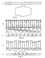
- FIGS. 10 and 11 show two advantageous windings for the motor mentioned at the outset, the manufacture of which is made considerably easier with the aid of the switching ring, in the case of FIG. 10 this is only possible for economical use as a mass product.
- the coil width w which corresponds to the coils of an eight-pole induction motor winding, is as precise as possible on the basis of this number of uses.
- the spatial angular distance between two successive coils of a coil group is, as is readily apparent from FIG. 10, 180 ° geometrically.
- Fig. 1 shows the two-pole universal motor winding arranged in the slots N1 to N18 of the rotor assembly, which are also provided for the induction motor winding, only a single loop winding of this winding being connected to the lamellae C6, C7 of the collector C being shown.
- the switching ring S By arranging the switching ring S on the underside of the induction motor winding shown in FIGS. 10 and 11 on the one hand and the collector C on the top of the universal motor winding shown in FIG. 1, it is to be indicated that in particular for the mechanical production of the two windings Collector C and switching ring S are advantageously to be arranged on opposite end faces of the rotor laminated core 9.
- the eight-pole induction motor winding shown in FIG. 10 can be machined with the aid of the electrically conductive switching ring S advantageous for this winding and provided with new hooks S1 to S9, as follows, for example. B. with the help of a flyer, in a simple and reliable manner: The beginning of the uninterrupted winding wire is z. B.
- Each coil group consists of three pairs of coils, each with three coils connected in series.
- a first pair of coils comprises e.g. B. the coils N1, N4; N7, N10; N13, N16.
- the series connections are each held together to form short-circuit circuits via the connections of the switching ring hooks S1 to S4, the entire winding also being able to be progressively wound with an uninterrupted winding wire in the case according to FIG. 11.
- the switching ring S the same switching ring type is used as a unit component in FIGS. 10 and 11.
Landscapes
- Engineering & Computer Science (AREA)
- Power Engineering (AREA)
- Windings For Motors And Generators (AREA)
- Insulation, Fastening Of Motor, Generator Windings (AREA)
- Manufacture Of Motors, Generators (AREA)
- Power Steering Mechanism (AREA)
Priority Applications (1)
| Application Number | Priority Date | Filing Date | Title |
|---|---|---|---|
| AT82100810T ATE13733T1 (de) | 1981-02-13 | 1982-02-04 | Verbindungsvorrichtung fuer wicklungsanfaenge und wicklungsenden der induktionsmotorlaeuferwicklung eines elektrischen motors. |
Applications Claiming Priority (2)
| Application Number | Priority Date | Filing Date | Title |
|---|---|---|---|
| DE3105318 | 1981-02-13 | ||
| DE3105318A DE3105318C2 (de) | 1981-02-13 | 1981-02-13 | Anordnung zum Kurzschließen der Anfänge und Enden der Spulengruppen einer Induktionsmotor-Läuferwicklung eines elektrischen Zweimotorenantriebs |
Publications (2)
| Publication Number | Publication Date |
|---|---|
| EP0058351A1 EP0058351A1 (de) | 1982-08-25 |
| EP0058351B1 true EP0058351B1 (de) | 1985-06-05 |
Family
ID=6124824
Family Applications (1)
| Application Number | Title | Priority Date | Filing Date |
|---|---|---|---|
| EP82100810A Expired EP0058351B1 (de) | 1981-02-13 | 1982-02-04 | Verbindungsvorrichtung für Wicklungsanfänge und Wicklungsenden der Induktionsmotorläuferwicklung eines elektrischen Motors |
Country Status (8)
| Country | Link |
|---|---|
| EP (1) | EP0058351B1 (cs) |
| AT (1) | ATE13733T1 (cs) |
| CS (1) | CS235007B2 (cs) |
| DD (1) | DD209328A5 (cs) |
| DE (2) | DE3105318C2 (cs) |
| DK (1) | DK58082A (cs) |
| HU (1) | HU183821B (cs) |
| PL (1) | PL136486B1 (cs) |
Families Citing this family (5)
| Publication number | Priority date | Publication date | Assignee | Title |
|---|---|---|---|---|
| DE19832680C2 (de) * | 1998-07-21 | 2001-03-29 | Sachsenwerk Gmbh | Variable Schaltverbindung für die Wicklungsanfänge und -enden einer Läuferwicklung einer drehenden elektrischen Maschine |
| US6147423A (en) * | 1999-09-30 | 2000-11-14 | Reliance Electric Technologies, Llc | Electric motor having improved rotor assembly, and method by which the rotor assembly is made |
| AU782017B2 (en) * | 1999-10-18 | 2005-06-30 | Lg Electronics Inc. | A driving unit for a drum type washing machine |
| EP1815581A1 (en) * | 2004-11-26 | 2007-08-08 | Matsushita Electric Industrial Co., Ltd. | Commutator motor and method of manufacturing the same |
| CN108599496B (zh) * | 2018-05-08 | 2019-07-23 | 刘建平 | 双定子永磁异步电动机及其调速控制电路 |
Family Cites Families (8)
| Publication number | Priority date | Publication date | Assignee | Title |
|---|---|---|---|---|
| DE276610C (cs) * | ||||
| US1803493A (en) * | 1927-11-12 | 1931-05-05 | Volet Rene Alfred Laurent | Rotor |
| FR740581A (fr) * | 1931-08-03 | 1933-01-27 | Brown | Moteur à induit à double cage d'écureuil |
| US3144572A (en) * | 1962-03-26 | 1964-08-11 | Smader Charles Louis | Terminal construction for electric motors |
| FR2247842A1 (en) * | 1973-10-10 | 1975-05-09 | Ferodo Sa | Rotor design for low power electric motor - ends of winding slot walls have winding guide discs with inclined fingers |
| DE2530294C3 (de) * | 1975-07-07 | 1982-10-28 | Siemens AG, 1000 Berlin und 8000 München | Elektrischer Waschautomatenantrieb |
| DE2643904C3 (de) * | 1976-09-29 | 1979-03-15 | Siemens Ag, 1000 Berlin Und 8000 Muenchen | Induktionsmotor mit einer gewickelten, in Läufernuten eingebrachten Läuferwicklung |
| DE2744419C2 (de) * | 1977-10-03 | 1985-02-21 | Siemens AG, 1000 Berlin und 8000 München | Hakenkommutator |
-
1981
- 1981-02-13 DE DE3105318A patent/DE3105318C2/de not_active Expired
-
1982
- 1982-02-04 EP EP82100810A patent/EP0058351B1/de not_active Expired
- 1982-02-04 AT AT82100810T patent/ATE13733T1/de not_active IP Right Cessation
- 1982-02-04 DE DE8282100810T patent/DE3263972D1/de not_active Expired
- 1982-02-04 CS CS82788A patent/CS235007B2/cs unknown
- 1982-02-05 DD DD82237226A patent/DD209328A5/de not_active IP Right Cessation
- 1982-02-11 DK DK58082A patent/DK58082A/da not_active Application Discontinuation
- 1982-02-12 HU HU82444A patent/HU183821B/hu not_active IP Right Cessation
- 1982-02-12 PL PL1982235047A patent/PL136486B1/pl unknown
Also Published As
| Publication number | Publication date |
|---|---|
| PL235047A1 (cs) | 1982-09-13 |
| EP0058351A1 (de) | 1982-08-25 |
| CS235007B2 (en) | 1985-04-16 |
| HU183821B (en) | 1984-06-28 |
| DD209328A5 (de) | 1984-04-25 |
| ATE13733T1 (de) | 1985-06-15 |
| DE3105318A1 (de) | 1982-08-19 |
| DE3105318C2 (de) | 1983-10-06 |
| DK58082A (da) | 1982-08-14 |
| DE3263972D1 (en) | 1985-07-11 |
| PL136486B1 (en) | 1986-02-28 |
Similar Documents
| Publication | Publication Date | Title |
|---|---|---|
| DE60119051T2 (de) | Elektromotor | |
| DE2211184C3 (de) | Scheibenanker | |
| DE10056555A1 (de) | Stator für dynamo-elektrische Maschinen | |
| DE19917579A1 (de) | Dynamo-elektrische Maschine und Verfahren zu ihrer Herstellung | |
| DE2744419A1 (de) | Elektromotor mit hakenkommutator | |
| DE102014217289A1 (de) | Wicklungsanordnung und Verfahren zur Herstellung einer Wicklungsanordnung | |
| EP2994980B1 (de) | Durchgehende, auf spulenträger gewickelte statorwicklung | |
| EP0058351B1 (de) | Verbindungsvorrichtung für Wicklungsanfänge und Wicklungsenden der Induktionsmotorläuferwicklung eines elektrischen Motors | |
| WO2009000586A2 (de) | Wickelkörper für einen elektromotor und verfahren zur herstellung eines wickelkörpers für einen elektromotor | |
| DE19757279C1 (de) | Kommutatormotor, insbesondere zum Antrieb eines Kraftfahrzeug-Servoantriebes, und Verfahren zu dessen Herstellung | |
| DE102012223668B4 (de) | Stator für eine elektrische Maschine und Verfahren zur Herstellung des Stators | |
| DE2117048C3 (de) | Verfahren zum Herstellen einer scheibenförmigen Wellenwicklung aus isoliertem Draht für eine elektrische Axialluftspaltmaschine | |
| WO2019057597A1 (de) | Elektrische maschine | |
| DE3105300C2 (de) | Elektrischer Zweimotorenantrieb, insbesondere zum Antrieb eines Waschautomaten | |
| DE8104018U1 (de) | Verbindungsvorrichtung mit in bestimmter weise angeschlossenen wicklungsanfaengen und wicklungsenden der induktionsmotor-laeuferwicklung eines elektrischen zweimotorenantriebs | |
| DE3012506C2 (de) | Kommutatormotor mit zwei Kommutatoren | |
| DE102020114065A1 (de) | Stator für einen Elektromotor | |
| DE2134490C3 (de) | Spaltpolmotor | |
| DE102009001543A1 (de) | Elektrische Maschine und Verfahren zur Herstellung einer elektrischen Maschine | |
| DE2609776C2 (de) | Ausgleichsleiteranordnung für Ankerwicklungen | |
| DE8104002U1 (de) | Elektrischer zweimotorenantrieb, insbesondere zum antrieb eines waschautomaten | |
| DE1613787A1 (de) | Einphasen-Asynchronmotor | |
| DE202010002424U1 (de) | Vorrichtung zum Wandeln von elektrischer in mechanische Energie und/oder umgekehrt sowie Wickelkörper für eine solche Vorrichtung | |
| DE2746995A1 (de) | Elektromotor mit hakenkommutator | |
| DE102020107909A1 (de) | Verfahren zum Herstellen einer Drahtspule, entsprechende Drahtspule sowie Verfahren zum Herstellen einer elektrischen Maschine |
Legal Events
| Date | Code | Title | Description |
|---|---|---|---|
| PUAI | Public reference made under article 153(3) epc to a published international application that has entered the european phase |
Free format text: ORIGINAL CODE: 0009012 |
|
| AK | Designated contracting states |
Designated state(s): AT BE CH DE FR GB IT NL SE |
|
| 17P | Request for examination filed |
Effective date: 19820916 |
|
| ITF | It: translation for a ep patent filed | ||
| GRAA | (expected) grant |
Free format text: ORIGINAL CODE: 0009210 |
|
| AK | Designated contracting states |
Designated state(s): AT BE CH DE FR GB IT LI NL SE |
|
| REF | Corresponds to: |
Ref document number: 13733 Country of ref document: AT Date of ref document: 19850615 Kind code of ref document: T |
|
| REF | Corresponds to: |
Ref document number: 3263972 Country of ref document: DE Date of ref document: 19850711 |
|
| ET | Fr: translation filed | ||
| PLBE | No opposition filed within time limit |
Free format text: ORIGINAL CODE: 0009261 |
|
| STAA | Information on the status of an ep patent application or granted ep patent |
Free format text: STATUS: NO OPPOSITION FILED WITHIN TIME LIMIT |
|
| 26N | No opposition filed | ||
| PGFP | Annual fee paid to national office [announced via postgrant information from national office to epo] |
Ref country code: CH Payment date: 19890524 Year of fee payment: 8 |
|
| PG25 | Lapsed in a contracting state [announced via postgrant information from national office to epo] |
Ref country code: LI Effective date: 19900228 Ref country code: CH Effective date: 19900228 |
|
| PGFP | Annual fee paid to national office [announced via postgrant information from national office to epo] |
Ref country code: NL Payment date: 19900228 Year of fee payment: 9 |
|
| PGFP | Annual fee paid to national office [announced via postgrant information from national office to epo] |
Ref country code: BE Payment date: 19900301 Year of fee payment: 9 |
|
| REG | Reference to a national code |
Ref country code: CH Ref legal event code: PL |
|
| PGFP | Annual fee paid to national office [announced via postgrant information from national office to epo] |
Ref country code: GB Payment date: 19910118 Year of fee payment: 10 |
|
| PGFP | Annual fee paid to national office [announced via postgrant information from national office to epo] |
Ref country code: SE Payment date: 19910222 Year of fee payment: 10 |
|
| ITTA | It: last paid annual fee | ||
| PG25 | Lapsed in a contracting state [announced via postgrant information from national office to epo] |
Ref country code: BE Effective date: 19910228 |
|
| PG25 | Lapsed in a contracting state [announced via postgrant information from national office to epo] |
Ref country code: NL Effective date: 19910901 |
|
| NLV4 | Nl: lapsed or anulled due to non-payment of the annual fee | ||
| PGFP | Annual fee paid to national office [announced via postgrant information from national office to epo] |
Ref country code: AT Payment date: 19920129 Year of fee payment: 11 |
|
| PG25 | Lapsed in a contracting state [announced via postgrant information from national office to epo] |
Ref country code: GB Effective date: 19920204 |
|
| PG25 | Lapsed in a contracting state [announced via postgrant information from national office to epo] |
Ref country code: SE Effective date: 19920205 |
|
| PGFP | Annual fee paid to national office [announced via postgrant information from national office to epo] |
Ref country code: FR Payment date: 19920220 Year of fee payment: 11 |
|
| GBPC | Gb: european patent ceased through non-payment of renewal fee | ||
| PG25 | Lapsed in a contracting state [announced via postgrant information from national office to epo] |
Ref country code: AT Effective date: 19930204 |
|
| PG25 | Lapsed in a contracting state [announced via postgrant information from national office to epo] |
Ref country code: FR Effective date: 19931029 |
|
| REG | Reference to a national code |
Ref country code: FR Ref legal event code: ST |
|
| PGFP | Annual fee paid to national office [announced via postgrant information from national office to epo] |
Ref country code: DE Payment date: 19940419 Year of fee payment: 13 |
|
| EUG | Se: european patent has lapsed |
Ref document number: 82100810.9 Effective date: 19920904 |
|
| PG25 | Lapsed in a contracting state [announced via postgrant information from national office to epo] |
Ref country code: DE Effective date: 19951101 |