EP0058754A2 - Dispositif pour l'injection de signaux numériques dans un système filaire - Google Patents
Dispositif pour l'injection de signaux numériques dans un système filaire Download PDFInfo
- Publication number
- EP0058754A2 EP0058754A2 EP81108638A EP81108638A EP0058754A2 EP 0058754 A2 EP0058754 A2 EP 0058754A2 EP 81108638 A EP81108638 A EP 81108638A EP 81108638 A EP81108638 A EP 81108638A EP 0058754 A2 EP0058754 A2 EP 0058754A2
- Authority
- EP
- European Patent Office
- Prior art keywords
- digital signals
- line system
- output
- transformer
- frequency
- Prior art date
- Legal status (The legal status is an assumption and is not a legal conclusion. Google has not performed a legal analysis and makes no representation as to the accuracy of the status listed.)
- Granted
Links
Images
Classifications
-
- H—ELECTRICITY
- H04—ELECTRIC COMMUNICATION TECHNIQUE
- H04B—TRANSMISSION
- H04B3/00—Line transmission systems
- H04B3/54—Systems for transmission via power distribution lines
- H04B3/56—Circuits for coupling, blocking, or by-passing of signals
-
- H—ELECTRICITY
- H04—ELECTRIC COMMUNICATION TECHNIQUE
- H04L—TRANSMISSION OF DIGITAL INFORMATION, e.g. TELEGRAPHIC COMMUNICATION
- H04L27/00—Modulated-carrier systems
- H04L27/02—Amplitude-modulated carrier systems, e.g. using on-off keying; Single sideband or vestigial sideband modulation
- H04L27/04—Modulator circuits; Transmitter circuits
-
- H—ELECTRICITY
- H04—ELECTRIC COMMUNICATION TECHNIQUE
- H04B—TRANSMISSION
- H04B2203/00—Indexing scheme relating to line transmission systems
- H04B2203/54—Aspects of powerline communications not already covered by H04B3/54 and its subgroups
- H04B2203/5404—Methods of transmitting or receiving signals via power distribution lines
- H04B2203/5416—Methods of transmitting or receiving signals via power distribution lines by adding signals to the wave form of the power source
-
- H—ELECTRICITY
- H04—ELECTRIC COMMUNICATION TECHNIQUE
- H04B—TRANSMISSION
- H04B2203/00—Indexing scheme relating to line transmission systems
- H04B2203/54—Aspects of powerline communications not already covered by H04B3/54 and its subgroups
- H04B2203/5429—Applications for powerline communications
- H04B2203/5458—Monitor sensor; Alarm systems
-
- H—ELECTRICITY
- H04—ELECTRIC COMMUNICATION TECHNIQUE
- H04B—TRANSMISSION
- H04B2203/00—Indexing scheme relating to line transmission systems
- H04B2203/54—Aspects of powerline communications not already covered by H04B3/54 and its subgroups
- H04B2203/5462—Systems for power line communications
- H04B2203/5483—Systems for power line communications using coupling circuits
Definitions
- the invention relates to a device for feeding digital signals into a line system in the form of an amplitude-modulated AC voltage.
- Devices of this type are used, for example, in the context of ripple control systems.
- the digital signals representing a pulse telegram are fed into the public power supply network as a line system with a sound-frequency alternating voltage as a carrier.
- Elaborate inverters preferably pulse inverters, are used for amplitude modulation of the audio frequency alternating voltage between a fixed amplitude value and zero amplitude value.
- ripple control technology since the digital signals must have a considerable range in order to reach ripple control receivers that are far apart. Such an effort is not justified for small transmission ranges.
- the invention has for its object to provide a device of the type mentioned, which can be produced inexpensively with little effort when limited to a small range.
- short range is understood to mean a range that allows receivers to be addressed within a building or within several neighboring buildings.
- the object is achieved in that the digital signals are led to one input of an exclusive-OR gate, the second input of which is connected to the output of a frequency generator, the periodic output signal of which is unipolar and of a higher frequency than the maximum repetition frequency of the digital signals that the primary winding of a transmitter is on the one hand the output of the Fre q uenzgenerators, on the other hand connected to the output of the exclusive-OR gate and in that the secondary winding of the transformer on two lines of the line system is connected.
- the device according to the invention can thus be constructed from inexpensive commercially available components.
- the carrier frequency for the digital signals is supplied by the frequency generator.
- the level of the carrier frequency depends on the conditions of the line system and the frequency and shape requirements of the digital signals.
- the shape of the output signals of the frequency generator is arbitrary within wide limits, so they can be, for example, sinusoidal, triangular, rectangular or trapezoidal. It is essential that these output signals are unipolar, i.e. that they are only on one side of the voltage zero line and preferably oscillate between a positive voltage value and the voltage value zero.
- a transformer with a ferrite core is used as the transformer.
- Such a transmitter allows a relatively distortion-free transmission of the input signals.
- the secondary winding of the transformer is connected to the line system via at least one capacitor.
- a high permeability for the amplitude-modulated alternating voltage on the other hand a good blocking effect against effects caused by the mains frequency.
- a frequency generator is used, the output signal of which is a pulse train consisting of rectangular pulses.
- An astable multi-vibrator can be used as such a frequency generator, for example, as a particularly inexpensive functional element.
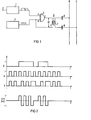
- the reference numeral 1 denotes an encoder which on the output side supplies as a digital signal information coded as a pulse train which is present at its input terminal 2, for example as an analog signal.
- analog signals can be, for example, temperature values of a heating system to be transmitted to another location in a building, a BCD-coded time of day or simply switch-on or switch-off commands for lighting fixtures distributed in a house.
- the output signal of encoder 1 is fed to input A of an exclusive OR gate 3.
- the second input B of the exclusive OR gate 3 is connected to the output of a frequency generator 4.
- the frequency generator 4 supplies a periodic output signal, the frequency of which - as is customary in the case of amplitude modulation - must be considerably higher than the maximum repetition frequency of the digital signals of the encoder 1, since the output signal of the frequency generator 4 represents the carrier frequency for the transmission of the digital signals.
- the frequency generator 4 is designed as a square-wave generator, the output signal of which represents a positive square-wave voltage without a further DC voltage component.
- the primary winding 5 of a transformer 6 is connected on the one hand to the output C of the exclusive OR gate 3 and on the other hand to the output of the frequency generator 4.
- the voltage U1 which corresponds to the difference between the instantaneous voltage values of the signals present at input B and output C of the exclusive OR gate 3, is thus present at this primary winding 5.
- the capacitors 8 and 9 block the backflow of line-frequency signals into the transformer 6, but on the other hand, because of their dimensioning, allow the signals to be fed into the line system from a frequency which is considerably higher than the line frequency into the line system.
- the coded signal at the input A of the exclusive OR gate 3, which contains the information to be transmitted, is shown in the first line.
- the second line below shows the unipolar periodic output signal of the frequency generator 4, which is present at the input B of the exclusive OR gate.
- This rectangular signal has a duty cycle of 1: 1 and fluctuates between the two fixed levels L and zero.
- the third line of FIG. 2 is the signal that is generated at output C of the exclusive OR gate represents.
Landscapes
- Engineering & Computer Science (AREA)
- Computer Networks & Wireless Communication (AREA)
- Signal Processing (AREA)
- Power Engineering (AREA)
- Dc Digital Transmission (AREA)
- Cable Transmission Systems, Equalization Of Radio And Reduction Of Echo (AREA)
- Digital Transmission Methods That Use Modulated Carrier Waves (AREA)
Applications Claiming Priority (2)
| Application Number | Priority Date | Filing Date | Title |
|---|---|---|---|
| DE19813106669 DE3106669A1 (de) | 1981-02-23 | 1981-02-23 | Einrichtung zur einspeisung von digitalen signalen in ein leitungssystem |
| DE3106669 | 1981-02-23 |
Publications (3)
| Publication Number | Publication Date |
|---|---|
| EP0058754A2 true EP0058754A2 (fr) | 1982-09-01 |
| EP0058754A3 EP0058754A3 (en) | 1983-08-17 |
| EP0058754B1 EP0058754B1 (fr) | 1985-06-26 |
Family
ID=6125524
Family Applications (1)
| Application Number | Title | Priority Date | Filing Date |
|---|---|---|---|
| EP81108638A Expired EP0058754B1 (fr) | 1981-02-23 | 1981-10-21 | Dispositif pour l'injection de signaux numériques dans un système filaire |
Country Status (4)
| Country | Link |
|---|---|
| EP (1) | EP0058754B1 (fr) |
| JP (1) | JPS57154963A (fr) |
| DE (2) | DE3106669A1 (fr) |
| ES (1) | ES509797A0 (fr) |
Cited By (4)
| Publication number | Priority date | Publication date | Assignee | Title |
|---|---|---|---|---|
| FR2567341A1 (fr) * | 1984-07-03 | 1986-01-10 | Charbonnages De France | Procede et equipement pour le transfert de signaux concernant une machine electrique munie d'un cable triphase d'alimentation |
| EP0156557A3 (fr) * | 1984-03-06 | 1987-07-15 | Controlonics Corporation | Emetteur-récepteur pour réseau local à stations multiples |
| WO2001069776A1 (fr) * | 2000-03-14 | 2001-09-20 | Gemplus | Dispositif de modulation d'amplitude, notamment pour lecteur sans contact, et procede de mise en oeuvre |
| FR2891070A1 (fr) * | 2005-09-16 | 2007-03-23 | Siemens Vdo Automotive Sas | Procede de calibration d'un systeme electronique integrant une unite de calcul embarquee |
Families Citing this family (3)
| Publication number | Priority date | Publication date | Assignee | Title |
|---|---|---|---|---|
| US4794620A (en) * | 1984-07-06 | 1988-12-27 | International Anasazi, Inc. | Radio frequency modem and method |
| JPS63234652A (ja) * | 1987-03-23 | 1988-09-29 | Fujitsu Ltd | 交番信号発生回路 |
| DE29701412U1 (de) * | 1997-01-28 | 1998-05-28 | Zumtobel Licht Gmbh, Dornbirn | Vorrichtung zum Übertragen von Informationen über Spannungsversorgungsleitungen |
Family Cites Families (4)
| Publication number | Priority date | Publication date | Assignee | Title |
|---|---|---|---|---|
| US2599675A (en) * | 1950-12-14 | 1952-06-10 | Rca Corp | Tone keyer |
| US3846705A (en) * | 1973-08-16 | 1974-11-05 | Sperry Rand Corp | Pulse amplitude modulated signal generator |
| US4092599A (en) * | 1976-11-26 | 1978-05-30 | Werner Yee | Annunciator communication system |
| DE2825240C2 (de) * | 1978-06-08 | 1983-09-22 | Siemens AG, 1000 Berlin und 8000 München | Rundsteueranlage |
-
1981
- 1981-02-23 DE DE19813106669 patent/DE3106669A1/de not_active Withdrawn
- 1981-10-21 DE DE8181108638T patent/DE3171137D1/de not_active Expired
- 1981-10-21 EP EP81108638A patent/EP0058754B1/fr not_active Expired
-
1982
- 1982-02-05 JP JP57017382A patent/JPS57154963A/ja active Pending
- 1982-02-22 ES ES509797A patent/ES509797A0/es active Granted
Cited By (8)
| Publication number | Priority date | Publication date | Assignee | Title |
|---|---|---|---|---|
| EP0156557A3 (fr) * | 1984-03-06 | 1987-07-15 | Controlonics Corporation | Emetteur-récepteur pour réseau local à stations multiples |
| FR2567341A1 (fr) * | 1984-07-03 | 1986-01-10 | Charbonnages De France | Procede et equipement pour le transfert de signaux concernant une machine electrique munie d'un cable triphase d'alimentation |
| EP0171302A1 (fr) * | 1984-07-03 | 1986-02-12 | Etablissement public dit: CHARBONNAGES DE FRANCE | Procédé et équipement pour le transfert de signaux concernant une machine électrique munie d'un câble triphasé d'alimentation |
| AU583522B2 (en) * | 1984-07-03 | 1989-05-04 | Charbonnages De France | Signal transfer method and equipment for electric machine equipped with three-phase power supply cable |
| US4862157A (en) * | 1984-07-03 | 1989-08-29 | Charbonnages De France | Signal transfer method and equipment for electric machine equipped with three-phase power supply cable |
| WO2001069776A1 (fr) * | 2000-03-14 | 2001-09-20 | Gemplus | Dispositif de modulation d'amplitude, notamment pour lecteur sans contact, et procede de mise en oeuvre |
| FR2806563A1 (fr) * | 2000-03-14 | 2001-09-21 | Gemplus Card Int | Procede de modulation d'amplitude, notamment pour lecteur sans contact, et dispositif de mise en oeuvre |
| FR2891070A1 (fr) * | 2005-09-16 | 2007-03-23 | Siemens Vdo Automotive Sas | Procede de calibration d'un systeme electronique integrant une unite de calcul embarquee |
Also Published As
| Publication number | Publication date |
|---|---|
| DE3106669A1 (de) | 1982-09-09 |
| DE3171137D1 (en) | 1985-08-01 |
| EP0058754A3 (en) | 1983-08-17 |
| EP0058754B1 (fr) | 1985-06-26 |
| ES8303857A1 (es) | 1983-02-01 |
| JPS57154963A (en) | 1982-09-24 |
| ES509797A0 (es) | 1983-02-01 |
Similar Documents
| Publication | Publication Date | Title |
|---|---|---|
| DE69611202T2 (de) | Infrarotzwischenverstärker | |
| EP0223315A2 (fr) | Disposition de circuit pour produire une tension continue à partir d'une tension d'entrée sinusoidale | |
| DE2932068C2 (de) | Schaltungsanordnung zum ständigen Erzeugen eines Rufwechselstromsignals vorgegebener Frequenz und Amplitude | |
| DE2644767C3 (de) | Schaltungsanordnung für einen Rundsteuerempfänger | |
| EP0058754B1 (fr) | Dispositif pour l'injection de signaux numériques dans un système filaire | |
| DE2922219C3 (de) | Elektronischer Sensor-Ein/Aus-Schalter | |
| DE2456344B2 (de) | Tonfrequenz-Rundsteueranlage | |
| DE2633876A1 (de) | Schaltungsanordnung zur erzeugung einer geregelten ausgangsspannung aus einer eingangsgleichspannung | |
| DE2807916B2 (de) | Wecksignalgenerator zur Verwendung in einer Teilnehmerverbindungsschaltung | |
| DE2903860C2 (de) | Einrichtung zur Gleichstromversorgung eines Verbrauchers und zur gleichzeitigen Informationsübertragung über ein Aderpaar | |
| EP0171470B1 (fr) | Dispositif d'alimentation d'émetteurs et de récepteurs d'un système de transmission de signaux | |
| DE2228008C3 (de) | Verfahren und Vorrichtung zur Erzeugung eines Sendesignals mit einer in einem starren Verhältnis zur Netzfrequenz des Stromversorgungsnetzes stehenden Sendefrequenz und Anwendung dieses Verfahrens | |
| AT401210B (de) | Schaltungsanordnung zur übertragung von kleinen, energiearmen und grossen, wesentlich energiereicheren signalen | |
| DE2130916B2 (de) | Übertragungsschaltung für digitale Signale | |
| DE1275637B (de) | Vielkanal-Modulations-Signaluebertragungssystem | |
| EP0089641B1 (fr) | Récepteur de télécommande,notamment pour commander des appareils électriques | |
| DE2254009A1 (de) | Energieversorgungskreis | |
| DE2718999A1 (de) | Spannungs- oder stromgeregelter spannungswandler | |
| EP0319104A2 (fr) | Générateur de signaux carrés | |
| DE2902443A1 (de) | Elektrischer wechselstromschalter, insbesondere fuer hausinstallationen | |
| DE3600170A1 (de) | Induktionsheizgeraet | |
| DE859032C (de) | Schaltung zur Erzeugung von Stromstoessen mit Hilfe eines gepolten Relais | |
| DE3533798A1 (de) | Trennuebertrager | |
| DE1413496C (de) | Schaltungsanordnung zur Umformung einer Gleichspannung in eine Wechselspannung beliebiger Kurvenform und veränderbarer Frequenz | |
| DE1914767C3 (de) | Rundsteuerempfangseinrichtung mit elektrischem Bandfilter |
Legal Events
| Date | Code | Title | Description |
|---|---|---|---|
| PUAI | Public reference made under article 153(3) epc to a published international application that has entered the european phase |
Free format text: ORIGINAL CODE: 0009012 |
|
| 17P | Request for examination filed |
Effective date: 19811021 |
|
| AK | Designated contracting states |
Designated state(s): CH DE FR GB IT |
|
| PUAL | Search report despatched |
Free format text: ORIGINAL CODE: 0009013 |
|
| AK | Designated contracting states |
Designated state(s): CH DE FR GB IT LI |
|
| ITF | It: translation for a ep patent filed | ||
| GRAA | (expected) grant |
Free format text: ORIGINAL CODE: 0009210 |
|
| AK | Designated contracting states |
Designated state(s): CH DE FR GB IT LI |
|
| REF | Corresponds to: |
Ref document number: 3171137 Country of ref document: DE Date of ref document: 19850801 |
|
| ET | Fr: translation filed | ||
| PLBE | No opposition filed within time limit |
Free format text: ORIGINAL CODE: 0009261 |
|
| STAA | Information on the status of an ep patent application or granted ep patent |
Free format text: STATUS: NO OPPOSITION FILED WITHIN TIME LIMIT |
|
| 26N | No opposition filed | ||
| PG25 | Lapsed in a contracting state [announced via postgrant information from national office to epo] |
Ref country code: LI Effective date: 19881031 Ref country code: CH Effective date: 19881031 |
|
| REG | Reference to a national code |
Ref country code: CH Ref legal event code: PL |
|
| PG25 | Lapsed in a contracting state [announced via postgrant information from national office to epo] |
Ref country code: DE Effective date: 19890701 |
|
| PG25 | Lapsed in a contracting state [announced via postgrant information from national office to epo] |
Ref country code: GB Effective date: 19891021 |
|
| GBPC | Gb: european patent ceased through non-payment of renewal fee | ||
| PG25 | Lapsed in a contracting state [announced via postgrant information from national office to epo] |
Ref country code: FR Effective date: 19900629 |
|
| REG | Reference to a national code |
Ref country code: FR Ref legal event code: ST |