EP0319104A2 - Générateur de signaux carrés - Google Patents
Générateur de signaux carrés Download PDFInfo
- Publication number
- EP0319104A2 EP0319104A2 EP88202730A EP88202730A EP0319104A2 EP 0319104 A2 EP0319104 A2 EP 0319104A2 EP 88202730 A EP88202730 A EP 88202730A EP 88202730 A EP88202730 A EP 88202730A EP 0319104 A2 EP0319104 A2 EP 0319104A2
- Authority
- EP
- European Patent Office
- Prior art keywords
- voltage
- pulse
- operational amplifier
- input
- inverting input
- Prior art date
- Legal status (The legal status is an assumption and is not a legal conclusion. Google has not performed a legal analysis and makes no representation as to the accuracy of the status listed.)
- Withdrawn
Links
- 239000003990 capacitor Substances 0.000 claims description 2
- 238000012216 screening Methods 0.000 claims description 2
- 238000007873 sieving Methods 0.000 abstract 1
- 230000005540 biological transmission Effects 0.000 description 7
- 238000005259 measurement Methods 0.000 description 2
- 230000010363 phase shift Effects 0.000 description 2
- 238000006243 chemical reaction Methods 0.000 description 1
- 238000010586 diagram Methods 0.000 description 1
- 238000002955 isolation Methods 0.000 description 1
- 238000012423 maintenance Methods 0.000 description 1
- 230000036962 time dependent Effects 0.000 description 1
- 230000001960 triggered effect Effects 0.000 description 1
Images
Classifications
-
- H—ELECTRICITY
- H03—ELECTRONIC CIRCUITRY
- H03K—PULSE TECHNIQUE
- H03K12/00—Producing pulses by distorting or combining sinusoidal waveforms
-
- H—ELECTRICITY
- H03—ELECTRONIC CIRCUITRY
- H03K—PULSE TECHNIQUE
- H03K5/00—Manipulating of pulses not covered by one of the other main groups of this subclass
- H03K5/01—Shaping pulses
- H03K5/08—Shaping pulses by limiting; by thresholding; by slicing, i.e. combined limiting and thresholding
- H03K5/082—Shaping pulses by limiting; by thresholding; by slicing, i.e. combined limiting and thresholding with an adaptive threshold
Definitions
- the invention relates to a square-wave generator with an operational amplifier for generating a square-wave pulse from an AC voltage.
- Intermediate amplifiers or regenerators for which a power supply is to be provided, are required at certain intervals for the transmission of messages via lines. For this purpose, it is common to supply a number of repeater positions remotely from a terminal.
- transformer constants are switched on between the supplying network and the transmission line to be supplied, which on the one hand achieves galvanic isolation from the supplying network and on the other hand the voltage fed into the transmission line becomes independent of line voltage fluctuations.
- branched cable networks it can happen that a cable route is unintentionally connected to two constants at the same time, because a further route is not only looped through for the message, but there is also a connection for the remote supply voltage.
- a device which, when a constant is disconnected from the mains, recognizes that voltage is still present from the other side and causes the constant to be switched off automatically from the transmission line.
- a phase angle measurement is carried out because the phase angle between current and voltage changes by approximately +90 degrees or -90 degrees when voltage is fed back on the line, and this change is used as a criterion for the switchover.
- the phase angle measurement it is necessary to derive rectangular pulses from the current and voltage values of the AC voltage.
- the invention is based on the object of specifying a square-wave generator which generates square-wave pulses from an AC voltage, whose pulse / pause ratio can be set and remains constant even with different amplitude values of the AC voltage.
- This object is achieved according to the invention with a rectangular generator with an operational amplifier in that a DC voltage obtained by rectification and screening from the AC voltage is present at the inverting input and a further voltage derived from the AC voltage is present at the non-inverting input.
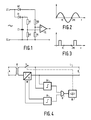
- a sinusoidal AC voltage is present at the input terminals E1 and E2, the course of which is shown in FIG. 2.
- the non-inverting input of an operational amplifier IC is connected via a rectifier diode D2 and a resistor R3 to the input terminal E1 and via a resistor R4 to the input terminal E2.
- the two resistors R3 and R4 form a voltage divider, so that only a proportion of the rectified input AC voltage which can be determined by the resistance ratio is supplied to the non-inverting input of the operational amplifier IC.
- the reference voltage is present at the inverting input of the operational amplifier IC.
- it is also connected to the input terminal E1 via a rectifier diode D1 and a resistor R1 in series therewith and via a resistor R2 to the input terminal E2.
- the two resistors R1 and R2 also form a voltage divider.
- a capacitor C1 is arranged in parallel with this voltage divider.
- the comparison voltage and thus the trigger threshold of the comparator formed with the operational amplifier IC in this circuit configuration can be set by appropriately dimensioning the resistors R1 and R2 of the voltage divider.
- the trigger threshold determines the pulse / pause ratio of the output pulse shown in FIG. 3.
- the arrangement shown ensures that only after a time dependent on the pulse / pause ratio of the output-side pulse train after the zero crossing of the AC sine voltage present at the input, the leading edge of the associated square-wave pulse arises at the output of the operational amplifier IC.
- the rear flank also appears at a corresponding time interval before the next zero crossing of the input sine AC voltage.
- Fig. 4 shows an embodiment for an application already described in the introduction.
- AC voltage is fed into a transmission line L via a transformer constant K, the public supply voltage network, for example, being connected to the pair of primary terminals A of the constant K.
- the intermediate amplifiers to be supplied are connected in parallel to the transmission line and are not shown in FIG. 4 for reasons of clarity.
- a square-wave generator Gu a square-wave pulse is derived from the AC voltage on line L, which pulse is applied to an input of AND circuit U.
- a further rectangular pulse Gi is derived, which is fed to a second input of the AND circuit U by a further rectangular generator Gi.
Landscapes
- Physics & Mathematics (AREA)
- Nonlinear Science (AREA)
- Amplifiers (AREA)
- Generation Of Surge Voltage And Current (AREA)
Applications Claiming Priority (2)
| Application Number | Priority Date | Filing Date | Title |
|---|---|---|---|
| DE3740894 | 1987-12-03 | ||
| DE19873740894 DE3740894A1 (de) | 1987-12-03 | 1987-12-03 | Rechteckgenerator |
Publications (2)
| Publication Number | Publication Date |
|---|---|
| EP0319104A2 true EP0319104A2 (fr) | 1989-06-07 |
| EP0319104A3 EP0319104A3 (fr) | 1990-04-25 |
Family
ID=6341757
Family Applications (1)
| Application Number | Title | Priority Date | Filing Date |
|---|---|---|---|
| EP88202730A Withdrawn EP0319104A3 (fr) | 1987-12-03 | 1988-11-30 | Générateur de signaux carrés |
Country Status (2)
| Country | Link |
|---|---|
| EP (1) | EP0319104A3 (fr) |
| DE (1) | DE3740894A1 (fr) |
Cited By (2)
| Publication number | Priority date | Publication date | Assignee | Title |
|---|---|---|---|---|
| US5821790A (en) * | 1996-04-24 | 1998-10-13 | Paragon Electric Company, Inc. | Power line synchronization conditioner |
| KR100424311B1 (ko) * | 2001-12-17 | 2004-03-24 | 엘지전자 주식회사 | 구형파 발생기 및 그 발생방법 |
Families Citing this family (3)
| Publication number | Priority date | Publication date | Assignee | Title |
|---|---|---|---|---|
| DE8905412U1 (de) * | 1989-04-28 | 1989-06-22 | Coufal, Hans-Peter, Wolfhalden | Elektronisches Gerät zur Entfeuchtung von Mauerwerk |
| CN110244609A (zh) * | 2019-05-31 | 2019-09-17 | 西安交通大学 | 一种消除半导体激光器干涉信号幅值调制的硬件电路 |
| CN110672891A (zh) * | 2019-11-07 | 2020-01-10 | 云南电网有限责任公司电力科学研究院 | 一种用于分压器标定的方波发生器 |
Family Cites Families (2)
| Publication number | Priority date | Publication date | Assignee | Title |
|---|---|---|---|---|
| US2952811A (en) * | 1956-06-14 | 1960-09-13 | Itt | Modulation synchronizing pulse generator |
| US4399414A (en) * | 1981-06-16 | 1983-08-16 | Bird David A | Low-noise pulse conditioner |
-
1987
- 1987-12-03 DE DE19873740894 patent/DE3740894A1/de not_active Withdrawn
-
1988
- 1988-11-30 EP EP88202730A patent/EP0319104A3/fr not_active Withdrawn
Cited By (2)
| Publication number | Priority date | Publication date | Assignee | Title |
|---|---|---|---|---|
| US5821790A (en) * | 1996-04-24 | 1998-10-13 | Paragon Electric Company, Inc. | Power line synchronization conditioner |
| KR100424311B1 (ko) * | 2001-12-17 | 2004-03-24 | 엘지전자 주식회사 | 구형파 발생기 및 그 발생방법 |
Also Published As
| Publication number | Publication date |
|---|---|
| DE3740894A1 (de) | 1989-06-15 |
| EP0319104A3 (fr) | 1990-04-25 |
Similar Documents
| Publication | Publication Date | Title |
|---|---|---|
| EP1058093A1 (fr) | Procédé et circuit d'alimentation et de surveillance du fonctionnement d'au moins un capteur | |
| DE2011483A1 (fr) | ||
| DE10207560A1 (de) | Verfahren zum Überwachen von dezentralen Energieerzegungsanlagen | |
| DE69613445T2 (de) | Anordnung zur fernsteuerung und fernüberwachung einer entladungslampe | |
| EP0631360B1 (fr) | Dispositif et procédé de surveillance de la position d'un commutateur | |
| DE2310885B2 (de) | Verfahren zur Gleichstromfernspeisung in einem System zur Übertragung und Verteilung von Hochfrequenz-Energie | |
| DE3049741C2 (de) | Einrichtung zur Versorgung und zur Überwachung des richtigen Arbeitens eines Eisenbahnsignals | |
| DE2152997B2 (de) | Elektronische Schaltanordnung mit optischen Signalkopplern | |
| EP0319104A2 (fr) | Générateur de signaux carrés | |
| DE2338882A1 (de) | Verfahren und fernwirksystem zum einund ausschalten von elektrischen verbrauchern | |
| DE3701046A1 (de) | Verfahren und vorrichtung zum synchronisieren von alarmanlagen | |
| DE2242458A1 (de) | Vorrichtung zur ununterbrochenen stromversorgung einer last durch zwei oder mehr gleichstromquellen | |
| DE2903860C2 (de) | Einrichtung zur Gleichstromversorgung eines Verbrauchers und zur gleichzeitigen Informationsübertragung über ein Aderpaar | |
| DE3428444A1 (de) | Ueberwachungseinrichtung fuer verkehrssignalanlagen | |
| DE3541549C2 (fr) | ||
| EP0058754B1 (fr) | Dispositif pour l'injection de signaux numériques dans un système filaire | |
| DE3430337C2 (de) | Einrichtung zur gleichzeitigen Speisung von voneinander unabhängigen Sendern und Empfängern eines Signalübertragungssystems | |
| DE2702551C2 (de) | Schaltung zum Überwachen von Signalen | |
| EP0222682B1 (fr) | Système de transmission de signaux pour un dispositif de protection à comparaison | |
| DE3330465A1 (de) | Spannungswandler | |
| DE3211815C2 (de) | Schaltungsanordnung zur Überwachung der Phasenfolge eines Drehstromnetzes | |
| DE3723877A1 (de) | Schaltungsanordnung zur gleisfreimeldung | |
| DE4218832A1 (de) | Verfahren zum Erkennen des Ausfalls einer Wechselspannung | |
| DE2405167C3 (de) | Schaltungsanordnung zur Überwachung einer einphasigen sinusförmigen Wechselspannung | |
| DE1102890B (de) | Schutzeinrichtung fuer Hochspannungsleitungen |
Legal Events
| Date | Code | Title | Description |
|---|---|---|---|
| PUAI | Public reference made under article 153(3) epc to a published international application that has entered the european phase |
Free format text: ORIGINAL CODE: 0009012 |
|
| AK | Designated contracting states |
Kind code of ref document: A2 Designated state(s): DE FR GB SE |
|
| PUAL | Search report despatched |
Free format text: ORIGINAL CODE: 0009013 |
|
| AK | Designated contracting states |
Kind code of ref document: A3 Designated state(s): DE FR GB SE |
|
| 17P | Request for examination filed |
Effective date: 19901023 |
|
| 17Q | First examination report despatched |
Effective date: 19920507 |
|
| STAA | Information on the status of an ep patent application or granted ep patent |
Free format text: STATUS: THE APPLICATION IS DEEMED TO BE WITHDRAWN |
|
| 18D | Application deemed to be withdrawn |
Effective date: 19930614 |