EP0059339A2 - Assemblage d'un essieu et d'une fusée des roues motrices des véhicules automobiles - Google Patents
Assemblage d'un essieu et d'une fusée des roues motrices des véhicules automobiles Download PDFInfo
- Publication number
- EP0059339A2 EP0059339A2 EP82100903A EP82100903A EP0059339A2 EP 0059339 A2 EP0059339 A2 EP 0059339A2 EP 82100903 A EP82100903 A EP 82100903A EP 82100903 A EP82100903 A EP 82100903A EP 0059339 A2 EP0059339 A2 EP 0059339A2
- Authority
- EP
- European Patent Office
- Prior art keywords
- journal
- locking ring
- support assembly
- cavities
- teeth
- Prior art date
- Legal status (The legal status is an assumption and is not a legal conclusion. Google has not performed a legal analysis and makes no representation as to the accuracy of the status listed.)
- Withdrawn
Links
Images
Classifications
-
- F—MECHANICAL ENGINEERING; LIGHTING; HEATING; WEAPONS; BLASTING
- F16—ENGINEERING ELEMENTS AND UNITS; GENERAL MEASURES FOR PRODUCING AND MAINTAINING EFFECTIVE FUNCTIONING OF MACHINES OR INSTALLATIONS; THERMAL INSULATION IN GENERAL
- F16C—SHAFTS; FLEXIBLE SHAFTS; ELEMENTS OR CRANKSHAFT MECHANISMS; ROTARY BODIES OTHER THAN GEARING ELEMENTS; BEARINGS
- F16C19/00—Bearings with rolling contact, for exclusively rotary movement
- F16C19/02—Bearings with rolling contact, for exclusively rotary movement with bearing balls essentially of the same size in one or more circular rows
- F16C19/14—Bearings with rolling contact, for exclusively rotary movement with bearing balls essentially of the same size in one or more circular rows for both radial and axial load
- F16C19/18—Bearings with rolling contact, for exclusively rotary movement with bearing balls essentially of the same size in one or more circular rows for both radial and axial load with two or more rows of balls
- F16C19/181—Bearings with rolling contact, for exclusively rotary movement with bearing balls essentially of the same size in one or more circular rows for both radial and axial load with two or more rows of balls with angular contact
- F16C19/183—Bearings with rolling contact, for exclusively rotary movement with bearing balls essentially of the same size in one or more circular rows for both radial and axial load with two or more rows of balls with angular contact with two rows at opposite angles
- F16C19/184—Bearings with rolling contact, for exclusively rotary movement with bearing balls essentially of the same size in one or more circular rows for both radial and axial load with two or more rows of balls with angular contact with two rows at opposite angles in O-arrangement
- F16C19/187—Bearings with rolling contact, for exclusively rotary movement with bearing balls essentially of the same size in one or more circular rows for both radial and axial load with two or more rows of balls with angular contact with two rows at opposite angles in O-arrangement with all four raceways integrated on parts other than race rings, e.g. fourth generation hubs
-
- B—PERFORMING OPERATIONS; TRANSPORTING
- B60—VEHICLES IN GENERAL
- B60B—VEHICLE WHEELS; CASTORS; AXLES FOR WHEELS OR CASTORS; INCREASING WHEEL ADHESION
- B60B27/00—Hubs
- B60B27/0005—Hubs with ball bearings
-
- B—PERFORMING OPERATIONS; TRANSPORTING
- B60—VEHICLES IN GENERAL
- B60B—VEHICLE WHEELS; CASTORS; AXLES FOR WHEELS OR CASTORS; INCREASING WHEEL ADHESION
- B60B35/00—Axle units; Parts thereof ; Arrangements for lubrication of axles
- B60B35/12—Torque-transmitting axles
- B60B35/18—Arrangement of bearings
-
- B—PERFORMING OPERATIONS; TRANSPORTING
- B60—VEHICLES IN GENERAL
- B60K—ARRANGEMENT OR MOUNTING OF PROPULSION UNITS OR OF TRANSMISSIONS IN VEHICLES; ARRANGEMENT OR MOUNTING OF PLURAL DIVERSE PRIME-MOVERS IN VEHICLES; AUXILIARY DRIVES FOR VEHICLES; INSTRUMENTATION OR DASHBOARDS FOR VEHICLES; ARRANGEMENTS IN CONNECTION WITH COOLING, AIR INTAKE, GAS EXHAUST OR FUEL SUPPLY OF PROPULSION UNITS IN VEHICLES
- B60K17/00—Arrangement or mounting of transmissions in vehicles
- B60K17/30—Arrangement or mounting of transmissions in vehicles the ultimate propulsive elements, e.g. ground wheels, being steerable
-
- F—MECHANICAL ENGINEERING; LIGHTING; HEATING; WEAPONS; BLASTING
- F16—ENGINEERING ELEMENTS AND UNITS; GENERAL MEASURES FOR PRODUCING AND MAINTAINING EFFECTIVE FUNCTIONING OF MACHINES OR INSTALLATIONS; THERMAL INSULATION IN GENERAL
- F16C—SHAFTS; FLEXIBLE SHAFTS; ELEMENTS OR CRANKSHAFT MECHANISMS; ROTARY BODIES OTHER THAN GEARING ELEMENTS; BEARINGS
- F16C19/00—Bearings with rolling contact, for exclusively rotary movement
- F16C19/02—Bearings with rolling contact, for exclusively rotary movement with bearing balls essentially of the same size in one or more circular rows
- F16C19/14—Bearings with rolling contact, for exclusively rotary movement with bearing balls essentially of the same size in one or more circular rows for both radial and axial load
- F16C19/18—Bearings with rolling contact, for exclusively rotary movement with bearing balls essentially of the same size in one or more circular rows for both radial and axial load with two or more rows of balls
- F16C19/181—Bearings with rolling contact, for exclusively rotary movement with bearing balls essentially of the same size in one or more circular rows for both radial and axial load with two or more rows of balls with angular contact
- F16C19/183—Bearings with rolling contact, for exclusively rotary movement with bearing balls essentially of the same size in one or more circular rows for both radial and axial load with two or more rows of balls with angular contact with two rows at opposite angles
- F16C19/184—Bearings with rolling contact, for exclusively rotary movement with bearing balls essentially of the same size in one or more circular rows for both radial and axial load with two or more rows of balls with angular contact with two rows at opposite angles in O-arrangement
- F16C19/186—Bearings with rolling contact, for exclusively rotary movement with bearing balls essentially of the same size in one or more circular rows for both radial and axial load with two or more rows of balls with angular contact with two rows at opposite angles in O-arrangement with three raceways provided integrally on parts other than race rings, e.g. third generation hubs
-
- F—MECHANICAL ENGINEERING; LIGHTING; HEATING; WEAPONS; BLASTING
- F16—ENGINEERING ELEMENTS AND UNITS; GENERAL MEASURES FOR PRODUCING AND MAINTAINING EFFECTIVE FUNCTIONING OF MACHINES OR INSTALLATIONS; THERMAL INSULATION IN GENERAL
- F16C—SHAFTS; FLEXIBLE SHAFTS; ELEMENTS OR CRANKSHAFT MECHANISMS; ROTARY BODIES OTHER THAN GEARING ELEMENTS; BEARINGS
- F16C35/00—Rigid support of bearing units; Housings, e.g. caps, covers
- F16C35/04—Rigid support of bearing units; Housings, e.g. caps, covers in the case of ball or roller bearings
- F16C35/06—Mounting or dismounting of ball or roller bearings; Fixing them onto shaft or in housing
- F16C35/063—Fixing them on the shaft
- F16C35/0635—Fixing them on the shaft the bore of the inner ring being of special non-cylindrical shape which co-operates with a complementary shape on the shaft, e.g. teeth, polygonal sections
-
- F—MECHANICAL ENGINEERING; LIGHTING; HEATING; WEAPONS; BLASTING
- F16—ENGINEERING ELEMENTS AND UNITS; GENERAL MEASURES FOR PRODUCING AND MAINTAINING EFFECTIVE FUNCTIONING OF MACHINES OR INSTALLATIONS; THERMAL INSULATION IN GENERAL
- F16D—COUPLINGS FOR TRANSMITTING ROTATION; CLUTCHES; BRAKES
- F16D1/00—Couplings for rigidly connecting two coaxial shafts or other movable machine elements
- F16D1/10—Quick-acting couplings in which the parts are connected by simply bringing them together axially
- F16D1/108—Quick-acting couplings in which the parts are connected by simply bringing them together axially having retaining means rotating with the coupling and acting by interengaging parts, i.e. positive coupling
-
- F—MECHANICAL ENGINEERING; LIGHTING; HEATING; WEAPONS; BLASTING
- F16—ENGINEERING ELEMENTS AND UNITS; GENERAL MEASURES FOR PRODUCING AND MAINTAINING EFFECTIVE FUNCTIONING OF MACHINES OR INSTALLATIONS; THERMAL INSULATION IN GENERAL
- F16D—COUPLINGS FOR TRANSMITTING ROTATION; CLUTCHES; BRAKES
- F16D3/00—Yielding couplings, i.e. with means permitting movement between the connected parts during the drive
- F16D3/16—Universal joints in which flexibility is produced by means of pivots or sliding or rolling connecting parts
- F16D3/20—Universal joints in which flexibility is produced by means of pivots or sliding or rolling connecting parts one coupling part entering a sleeve of the other coupling part and connected thereto by sliding or rolling members
- F16D3/22—Universal joints in which flexibility is produced by means of pivots or sliding or rolling connecting parts one coupling part entering a sleeve of the other coupling part and connected thereto by sliding or rolling members the rolling members being balls, rollers, or the like, guided in grooves or sockets in both coupling parts
- F16D3/223—Universal joints in which flexibility is produced by means of pivots or sliding or rolling connecting parts one coupling part entering a sleeve of the other coupling part and connected thereto by sliding or rolling members the rolling members being balls, rollers, or the like, guided in grooves or sockets in both coupling parts the rolling members being guided in grooves in both coupling parts
-
- F—MECHANICAL ENGINEERING; LIGHTING; HEATING; WEAPONS; BLASTING
- F16—ENGINEERING ELEMENTS AND UNITS; GENERAL MEASURES FOR PRODUCING AND MAINTAINING EFFECTIVE FUNCTIONING OF MACHINES OR INSTALLATIONS; THERMAL INSULATION IN GENERAL
- F16B—DEVICES FOR FASTENING OR SECURING CONSTRUCTIONAL ELEMENTS OR MACHINE PARTS TOGETHER, e.g. NAILS, BOLTS, CIRCLIPS, CLAMPS, CLIPS OR WEDGES; JOINTS OR JOINTING
- F16B2200/00—Constructional details of connections not covered for in other groups of this subclass
- F16B2200/40—Clamping arrangements where clamping parts are received in recesses of elements to be connected
- F16B2200/403—Threaded clamping parts
-
- F—MECHANICAL ENGINEERING; LIGHTING; HEATING; WEAPONS; BLASTING
- F16—ENGINEERING ELEMENTS AND UNITS; GENERAL MEASURES FOR PRODUCING AND MAINTAINING EFFECTIVE FUNCTIONING OF MACHINES OR INSTALLATIONS; THERMAL INSULATION IN GENERAL
- F16C—SHAFTS; FLEXIBLE SHAFTS; ELEMENTS OR CRANKSHAFT MECHANISMS; ROTARY BODIES OTHER THAN GEARING ELEMENTS; BEARINGS
- F16C2326/00—Articles relating to transporting
- F16C2326/01—Parts of vehicles in general
- F16C2326/02—Wheel hubs or castors
-
- F—MECHANICAL ENGINEERING; LIGHTING; HEATING; WEAPONS; BLASTING
- F16—ENGINEERING ELEMENTS AND UNITS; GENERAL MEASURES FOR PRODUCING AND MAINTAINING EFFECTIVE FUNCTIONING OF MACHINES OR INSTALLATIONS; THERMAL INSULATION IN GENERAL
- F16D—COUPLINGS FOR TRANSMITTING ROTATION; CLUTCHES; BRAKES
- F16D3/00—Yielding couplings, i.e. with means permitting movement between the connected parts during the drive
- F16D3/16—Universal joints in which flexibility is produced by means of pivots or sliding or rolling connecting parts
- F16D3/20—Universal joints in which flexibility is produced by means of pivots or sliding or rolling connecting parts one coupling part entering a sleeve of the other coupling part and connected thereto by sliding or rolling members
- F16D3/22—Universal joints in which flexibility is produced by means of pivots or sliding or rolling connecting parts one coupling part entering a sleeve of the other coupling part and connected thereto by sliding or rolling members the rolling members being balls, rollers, or the like, guided in grooves or sockets in both coupling parts
- F16D3/223—Universal joints in which flexibility is produced by means of pivots or sliding or rolling connecting parts one coupling part entering a sleeve of the other coupling part and connected thereto by sliding or rolling members the rolling members being balls, rollers, or the like, guided in grooves or sockets in both coupling parts the rolling members being guided in grooves in both coupling parts
- F16D2003/22326—Attachments to the outer joint member, i.e. attachments to the exterior of the outer joint member or to the shaft of the outer joint member
Definitions
- This invention relates to a support assembly for road vehicle wheels, and in particular to a support assembly for the drive wheels of motor vehicles.
- a support assembly for motor vehicle wheels is known to usually comprise a hub for the wheels, a shaft, a spindle and a bearing with a structure which is very integrated with the rest of the mechanical members of the support, so as to reduce the number of necessary members and their weights, and to simplify the structure and construction of the wheel support assembly.
- the rolling bearing of the drive wheels performs various functions, acting simultaneously as a hub for the wheels, as a bearing, as a shaft and as a spindle, by virtue of its special structure.
- the said bearing which is usually of the mixed type consisting of two rows of oblique balls, comprises a substantially cylindrical inner race provided at one end with a flange for fixing to a vehicle wheel and with an inner surface in which a splined coupling is formed, and a substantially cylindrical outer race provided, at the opposite end to said end of the inner race, with a flange for fixing to the upright of a suspension for said wheel.
- the rolling bodies slidable in suitable tracks, are disposed in the cavity lying between the inner race and outer race, and are isolated from the environment external to said cavity by means of known seal assemblies of the type consisting of a single or double sliding lip and a slinger shield, disposed between the inner race and outer race.
- the described structural design is not without drawbacks.
- the need to transmit the torque from the ball joint to the wheel by way of the inner race of the bearing means that a very accurate splined coupling must be provided between the joint and the inner race, with consequent considerable machining difficulties and high cost.
- This is because very narrow tolerances are required, with perfect centering between the axis of the inner race and the axis of the splined coupling.
- the presence of the flanges on the opposite ends of the outer race and inner race makes it very difficult to insert the rolling bodies and to assemble the tearing, so making it necessary to limit the maximum number of rolling bodies which can be inserted. This means that the bearings must be over-sized in order to prevent overloading.
- the object of the present invention is to provide a support assembly for vehicle drive wheels which is free from the aforesaid drawbacks.
- a support assembly for a vehicle drive wheel comprising at least one inner race provided with a fixing flange for said wheel, and an outer race provided with a flange for fixing to an upright of a suspension for said wheel, and two rows of rolling bodies disposed between said two races and arranged to roll on tracks of said races, said inner race being torsionally rigid with a ball joint element arranged to transmit motion to said wheel, characterised in that said joint element is provided with a journal having a cylindrical surface arranged to engage with the inner surface of said inner race, and by comprising a locking ring provided with teeth arranged to engage with a first set of cavities provided in an end portion of said journal and a second set of cavities provided in said inner race, and axial thrust means for said locking ring arranged to keep said teeth of said locking ring engaged with said cavities.
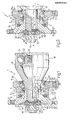
- the reference numeral 1 indicates overall a support assembly for motor vehicle driving wheels, comprising an outer race 2, an inner race 3 and two rows 4 of balls 5 which roll between annular tracks 6 provided in the inner surface 7 of the outer race 2, and annular tracks 8 and 11 provided respectively in the outer surface 12 of the inner race 3 and in the outer surface 13 of a journal 15 pertaining to a ball joint 16 of known type.
- the tracks 6 are offset relative to the tracks 8 and 11, which are spaced apart by a distance greater than the distance between the tracks 6 of the outer race 2, such that the balls 5 can absorb both radial and axial loads.
- the first inner race 3 is provided with a flange 18 formed in one piece therewith at an end 20, and arranged to connect the race 3 to a vehicle wheel (not shown).
- the journal 15 is formed in one piece with an outer member 21 of the ball joint 16, which also comprises an inner member 22 housed in the member 21 and provided with a bore in which a splined coupling 23 is provided, and balls 24 disposed between the outer member 21 and inner member 22.
- the outer race 3 is slidably mounted over the journal 15 until it rests against a shoulder 25 of the journal 15 by way of that end 26 distant from the end 20.
- the outer race 2 is also provided with a substantially quadrangular flange "ormed in one piece therewith on that end 28 facing the ball joint 16.
- the flange 27 is arranged to be connected to an upright of a suspension (not shown) by means of threaded bores 29 provided at the corners of the flange 26.
- the flange 18 also possesses a set of threaded bores 31 for its fixing to said wheel, not shown, and also possesses at least one threaded bore 32 for a reference pin, not shown.
- the balls 5 of each row 4 are retained by a spacer cage 33, contained together with said balls 5 in an annular cavity 34 lying between the outer race 2 and inner race 3.
- the cavity 34 is closed at its ends by two seal assemblies of the known sliding lip type, so as to isolate the balls 5 from any contaminants external to the cavity 34, and to retain the necessary lubricant therein.
- a tight shield 38 At the opposite end 28 of the outer race 2 there is disposed a tight shield 38, of which the lip 39 slides on the surface 13 of the journal 15.
- a slinger shield 40 is also keyed on the journal 15 externally to the outer race 2, in a position facing the shield 38.
- the journal 15 has a threaded end 41, and an end portion 4la provided with a toothed frusto-conical surface 42, which is faced by a toothed frusto-conical surface 43 with internal toothing provided in a shallow recess 44 formed in the race 3 in the front surface 45 of the flange 18.
- a locking ring 46 On the threaded end 41 of the journal 15 there is also slidably mounted a locking ring 46 provided with an outer toothed frusto-conical surface 47 arranged to engage with the toothed surface 43, and with an inner toothed frusto-conical surface 48 provided in a shallow recess 49 in the ring 46, and arranged to engage with the toothed surface 42.
- the locking ring 46 is urged against the toothed surfaces 42 and 43 by means of a nut 50 which is screwed on to the threaded ('od 41 such that teeth 51 of the toothed surfaces 47 and 48 engage with cavities 52 and 53 of the toothed surfaces 42 and 43 respectively.
- the support assembly 1 is disposed between the wheel and the axle shaft of a vehicle by fixing the flange 18 to the wheel, the flange 27 to the vehicle suspension upright, and the splined coupling 32 to the axle shaft.
- the torque is transmitted by the axle shaft to the wheel by way of the joint 16 followed by the flange 18 of the inner race 3 by virtue of the locking ring 46, of which the teeth 51 simultaneously engage the cavities 52 and 53 of the toothed surfaces 42 and 43 provided on the journal 15 and in the shallow recess 44 of the inner race 3.
- Figure 2 shows a modification of the support assembly of Figure 1, in which the track 11 is not formed on the journal 15, but on a second inner race 54 slidably mounted on the journal 15 in a like manner to the first inner race 3.
- the races 3 and 54 are in this case locked axially by a shoulder 25a provided on one end of the outer member 21 of the joint 16.
- the nut 50 also locks both the races 3 and 54, and keeps the locking ring 46 engaged with the journal 15 and race 3.
- the remaining components of the support assembly 1 of Figure 2 are completely identical to those already described, and are indicated by the same reference numerals.
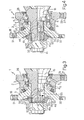
- FIGS 3 and 4 show two further modifications of the support assembly of Figure 1, common parts being indicated by the same reference numerals.
- the assembly 1 of Figure 3 is similar to the already described assembly of Figure 1, from which it differs only by the system for locking the race 3 on to the journal 15.
- the journal 15 comprises a splined area 55 provided externally to the race 3 in the outer surface 56 of the journal 15.
- the race 3 comprises a toothed surface 57 with front toothing provided on the flat base wall 58 of the shallow recess 44 and substantially perpendicular to the axis of the journal 15.
- the ring 46 also comprises a front toothed surface 61 substantially perpendicular to the journal 15 and arranged to engage with the toothed surface 57 against which the ring 46 is urged by a nut 50 screwed on to the threaded end 41.
- the teeth 51 of the splined area 60 and of the toothed surface 61 engage with the corresponding cavities 52 and 53 of the splined area 50 of the journal 15 and of the toothed surface 57 of the inner race 3 respectively, to transmit the drive torque from the journal 15 to the flange 1 8.
- the journal 15 comprises on its end portion 4la a splined area 55 external to the race 3, and this latter comprises a frusto-conical toothed surface with internal toothing 43, facing the splined area 55 and provided on the shallow recess 44.
- the locking ring 46 is keyed on to the journal 15 by means of a splined area 60 provided in its inner surface 59 and engaged with the splined area 55, and comprises a frusto-conical toothed surface with external toothing 47 arranged to engage with the toothed surface 43 under the thrust of a nut 50 screwed on to the end 41.
- the teeth 51 of the ring 46 engaged in the corresponding cavities 52 and 53 of the splined area 55 and toothed surface 43 enable the' drive torque to be transmitted from the journal 15 to the race 3 and then to the vehicle wheels.
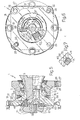
- FIGS. 5 and 6 illustrate a further embodiment of the support assembly 1, in which the parts common to the embodiments already illustrated are indicated by the same reference numerals.
- the support assembly illustrated in Figures 5 and 6 is similar to the assemblies of Figures 1, 3 and 4, from which it differs by the manner in which the race 3 is locked to the journal 15.
- This latter possesses a threaded end 41 having an outer diameter less than that of the remainder of the journal 15, and bounded by a groove 62.
- In the outer surface 56 of the end portion 4la there are provided three equidistant cavities 63, each of which when viewed in plan is of substantially parabolic shape, and comprises a base surface 64 which is inclined to the axis of the journal 15.
- three equidistant cavities 65 comprising an inclined base wall 66 with its slope in the opposite direction to that of the surface 64, these having a substantially rectangular shape when viewed in cross-section ( Figure 7).
- a nut 67 On the threaded end 41 there is screwed a nut 67, in the front surface 68 of which there is provided a cavity 69 housing a locking ring 70 which tapers outwards and is provided with three substantially parallelepiped equidistant teeth 71 arranged to engage with the facing seats 63 and 65.
- each tooth 71 is provided with two inclined surfaces 72 and 73 of opposite slope, arranged to adhere by friction to the corresponding inclined surfaces 64 and 66 of the facing seats 63 and 65 respectively.
- the ring 70 is urged by the nut 67 against the race 3 along the journal 15, so rigidly keying the former to the latter by virtue of the teeth 71 which behave as keys, to transmit the drive torque by friction.
- the threaded end 41 is clinched over the nut 67 by means of a punch (not shown), in order to create a bulge 74 for locking the nut 67.
Landscapes
- Engineering & Computer Science (AREA)
- General Engineering & Computer Science (AREA)
- Mechanical Engineering (AREA)
- Chemical & Material Sciences (AREA)
- Combustion & Propulsion (AREA)
- Transportation (AREA)
- Rolling Contact Bearings (AREA)
- Vehicle Body Suspensions (AREA)
Applications Claiming Priority (2)
| Application Number | Priority Date | Filing Date | Title |
|---|---|---|---|
| IT67267/81A IT1144121B (it) | 1981-02-27 | 1981-02-27 | Complesso di supporto per le ruote di veicoli |
| IT6726781 | 1981-02-27 |
Publications (2)
| Publication Number | Publication Date |
|---|---|
| EP0059339A2 true EP0059339A2 (fr) | 1982-09-08 |
| EP0059339A3 EP0059339A3 (fr) | 1983-04-27 |
Family
ID=11300990
Family Applications (1)
| Application Number | Title | Priority Date | Filing Date |
|---|---|---|---|
| EP82100903A Withdrawn EP0059339A3 (fr) | 1981-02-27 | 1982-02-09 | Assemblage d'un essieu et d'une fusée des roues motrices des véhicules automobiles |
Country Status (4)
| Country | Link |
|---|---|
| US (1) | US4433877A (fr) |
| EP (1) | EP0059339A3 (fr) |
| JP (1) | JPS57158103A (fr) |
| IT (1) | IT1144121B (fr) |
Cited By (9)
| Publication number | Priority date | Publication date | Assignee | Title |
|---|---|---|---|---|
| DE3246233A1 (de) * | 1982-12-14 | 1984-06-14 | Uni-Cardan Ag, 5200 Siegburg | Vorrichtung zum uebertragen eines drehmomentes |
| DE3435853A1 (de) * | 1984-09-29 | 1986-04-10 | SKF GmbH, 8720 Schweinfurt | Verdrehsichere befestigung eines maschinenelements |
| EP0237794A3 (en) * | 1986-03-15 | 1988-02-03 | Werner Jacob | Bearing assembly for the driven wheels of an automotive vehicle |
| DE3907105A1 (de) * | 1989-03-04 | 1990-09-13 | Kugelfischer G Schaefer & Co | Radlagerung fuer angetriebene raeder |
| GB2233404A (en) * | 1989-06-21 | 1991-01-09 | Kugelfischer G Schaefer & Co | A wheel-bearing for a motor vehicle |
| CN101132885B (zh) * | 2005-03-01 | 2010-05-19 | 温克铸型两合公司 | 在第一部件和至少另一部件间建立螺钉连接的装置和方法 |
| EP2045464B2 (fr) † | 2007-10-01 | 2016-08-24 | Siemens Aktiengesellschaft | Palier pour pales à pas d'éolienne |
| FR3052103A1 (fr) * | 2016-06-04 | 2017-12-08 | Ntn-Snr Roulements | Assemblage de roue motrice de vehicule automobile |
| DE102017124694A1 (de) | 2017-10-23 | 2019-04-25 | Avl Emission Test Systems Gmbh | Steuerschrankanordnung |
Families Citing this family (34)
| Publication number | Priority date | Publication date | Assignee | Title |
|---|---|---|---|---|
| DE3239121C2 (de) * | 1982-10-22 | 1984-08-09 | Uni-Cardan Ag, 5200 Siegburg | Lagerungsanordnung einer über ein Gleichlaufdrehgelenk antreibbaren Radnabe |
| JPS59165202U (ja) * | 1983-04-21 | 1984-11-06 | 日本精工株式会社 | 車輪用軸受組立体 |
| JPS6124819A (ja) * | 1984-07-13 | 1986-02-03 | Chubu Bearing Seisakusho:Kk | 合成樹脂製軸受 |
| US4624597A (en) * | 1984-08-23 | 1986-11-25 | Reliance Electric Company | Flanged bushing mounting adaptor |
| NL8403209A (nl) * | 1984-10-22 | 1986-05-16 | Skf Ind Trading & Dev | Wentellager-constructie. |
| JPS63110001A (ja) * | 1986-10-27 | 1988-05-14 | Ntn Toyo Bearing Co Ltd | 自動車の駆動車輪用軸受装置 |
| US4969753A (en) * | 1987-05-29 | 1990-11-13 | Ntn Toyo Bearing Co., Ltd. | Wheel bearing assembly for automotive wheel |
| JPH0512739U (ja) * | 1990-11-28 | 1993-02-19 | 有限会社シー・エス・ユー | ローラ |
| DE4219213C2 (de) * | 1992-06-12 | 1995-04-20 | Loehr & Bromkamp Gmbh | Lageranordnung für eine Radnaben-Gleichlaufdrehgelenk-Einheit |
| DE4425732A1 (de) * | 1994-07-21 | 1996-01-25 | Kugelfischer G Schaefer & Co | Radlagereinheit |
| DE19518678C1 (de) * | 1995-05-22 | 1996-10-31 | Fichtel & Sachs Ag | Anbindung eines Schwungrades an die Kurbelwelle |
| EP0921018B1 (fr) * | 1997-12-06 | 2005-02-16 | Iprotec Maschinen- und Edelstahlprodukte GmbH | Suspension de roue |
| JP2001171308A (ja) * | 1999-12-15 | 2001-06-26 | Ntn Corp | 駆動車輪用軸受装置 |
| US6857786B2 (en) * | 2000-02-01 | 2005-02-22 | Frank Victor Csik | Constant velocity joint integrated to wheel bearing and to axially adjustable hub |
| US6546828B2 (en) * | 2001-03-02 | 2003-04-15 | Trw Inc. | Apparatus for connecting a vehicle steering wheel to a steering shaft |
| JP2003089301A (ja) * | 2001-09-18 | 2003-03-25 | Ntn Corp | 駆動車輪用軸受装置 |
| JP2003191709A (ja) * | 2001-12-28 | 2003-07-09 | Koyo Seiko Co Ltd | 転がり軸受装置 |
| DE10218339B4 (de) * | 2002-04-24 | 2005-04-21 | Südrad GmbH Radtechnik | Scheibenrad aus Blech für Kraftfahrzeuge und Verfahren für dessen Herstellung |
| US6857835B2 (en) * | 2002-09-11 | 2005-02-22 | Visteon Global Technologies, Inc. | Wheel end assembly with locking fastener |
| DE10355684B4 (de) | 2003-11-28 | 2015-07-16 | Schaeffler Technologies AG & Co. KG | Verfahren und Montagevorrichtung zum Herstellen einer Drehverbindung |
| JP2006096143A (ja) * | 2004-09-29 | 2006-04-13 | Jtekt Corp | 車両用ハブユニット |
| DE102005018126A1 (de) * | 2005-04-20 | 2006-10-26 | Schaeffler Kg | Radlagergelenkeinheit |
| DE102005023343A1 (de) * | 2005-05-17 | 2006-11-23 | Otto Sauer Achsenfabrik Gmbh | Lageranordnung |
| US8480306B2 (en) * | 2006-06-14 | 2013-07-09 | Ntn Corporation | Bearing unit for driving wheels |
| JP2008082352A (ja) * | 2006-09-25 | 2008-04-10 | Jtekt Corp | 車輪用軸受 |
| WO2009012798A1 (fr) * | 2007-07-25 | 2009-01-29 | Ab Skf | Unité de transfert de couple |
| JP4846672B2 (ja) * | 2007-08-03 | 2011-12-28 | Ntn株式会社 | 車軸軸受及び車輪軸受装置 |
| JP2010202125A (ja) * | 2009-03-05 | 2010-09-16 | Jtekt Corp | 駆動車輪用軸受装置、及びこの駆動車輪用軸受装置の製造方法 |
| US8869962B2 (en) | 2010-09-20 | 2014-10-28 | Schaeffler Technologies AG & Co. KG | Wheel spindle drive element |
| JP5942650B2 (ja) * | 2012-07-10 | 2016-06-29 | 日産自動車株式会社 | 車軸支持構造 |
| JP6306458B2 (ja) * | 2014-07-15 | 2018-04-04 | Ntn株式会社 | 等速ジョイントのサポート軸受および等速ジョイントの外輪 |
| CN109723727A (zh) * | 2017-10-30 | 2019-05-07 | 西门子公司 | 编码器 |
| EP4097367B1 (fr) * | 2020-01-27 | 2023-12-20 | Volvo Truck Corporation | Verrou rotationel sur la bague intérieure d'un palier externe pour éviter une rondelle d'arrêt |
| IL277061A (en) * | 2020-08-31 | 2022-03-01 | Ree Automotive Ltd | Wheel drive assembly |
Family Cites Families (13)
| Publication number | Priority date | Publication date | Assignee | Title |
|---|---|---|---|---|
| US1922929A (en) | 1931-02-02 | 1933-08-15 | J C Lawrence | Means for keying members on shafts |
| US2128068A (en) | 1935-11-15 | 1938-08-23 | Productive Inventions Inc | Windshield wiper arm |
| US2605121A (en) | 1950-05-12 | 1952-07-29 | Willis B Ensinger | Drive washer |
| US2730387A (en) | 1952-01-15 | 1956-01-10 | Gen Electric | Apparatus for preventing relative motion between a shaft and a hub |
| US2675044A (en) | 1952-05-08 | 1954-04-13 | Illinois Tool Works | Nut and washer assembly |
| CH408553A (de) * | 1963-03-12 | 1966-02-28 | Reich Maschf Gmbh Karl | Befestigung eines Zahnrades kleinen Durchmessers am Ende einer Welle |
| NL6805109A (fr) * | 1968-04-10 | 1969-10-14 | ||
| DE2119325C3 (de) * | 1971-04-21 | 1973-10-04 | Wgw Westdeutsche Getriebe- Und Kupplungswerke Gmbh, 4630 Bochum | Formschlussige Kupplung zur Übertragung großer Drehmomente |
| FR2183543B1 (fr) * | 1972-05-09 | 1974-09-27 | Glaenzer Spicer Sa | |
| NL176011C (nl) | 1974-09-30 | 1985-02-01 | Skf Ind Trading & Dev | Lagereenheid. |
| DE2843597A1 (de) * | 1978-10-06 | 1980-04-17 | Kugelfischer G Schaefer & Co | Zweireihige schraeglagerung fuer antreibbare kraftfahrzeugraeder |
| FR2455209B2 (fr) | 1979-04-24 | 1986-07-25 | Glaenzer Spicer Sa | Roulement a deux rangees d'elements de roulement et dispositif de montage de roue de vehicule |
| US4306466A (en) | 1979-09-04 | 1981-12-22 | Coveney Howard W | Wheel security apparatus |
-
1981
- 1981-02-27 IT IT67267/81A patent/IT1144121B/it active
-
1982
- 1982-02-09 EP EP82100903A patent/EP0059339A3/fr not_active Withdrawn
- 1982-02-18 US US06/349,703 patent/US4433877A/en not_active Expired - Fee Related
- 1982-02-27 JP JP57031637A patent/JPS57158103A/ja active Pending
Cited By (13)
| Publication number | Priority date | Publication date | Assignee | Title |
|---|---|---|---|---|
| DE3246233A1 (de) * | 1982-12-14 | 1984-06-14 | Uni-Cardan Ag, 5200 Siegburg | Vorrichtung zum uebertragen eines drehmomentes |
| FR2537678A1 (fr) * | 1982-12-14 | 1984-06-15 | Uni Cardan Ag | Dispositif pour la transmission d'un couple |
| GB2131916A (en) * | 1982-12-14 | 1984-06-27 | Uni Cardan Ag | A self-centering torque transmission assembly |
| DE3435853A1 (de) * | 1984-09-29 | 1986-04-10 | SKF GmbH, 8720 Schweinfurt | Verdrehsichere befestigung eines maschinenelements |
| EP0237794A3 (en) * | 1986-03-15 | 1988-02-03 | Werner Jacob | Bearing assembly for the driven wheels of an automotive vehicle |
| DE3907105A1 (de) * | 1989-03-04 | 1990-09-13 | Kugelfischer G Schaefer & Co | Radlagerung fuer angetriebene raeder |
| GB2233404A (en) * | 1989-06-21 | 1991-01-09 | Kugelfischer G Schaefer & Co | A wheel-bearing for a motor vehicle |
| GB2233404B (en) * | 1989-06-21 | 1993-03-17 | Kugelfischer G Schaefer & Co | A wheel-bearing for a motor-vehicle |
| CN101132885B (zh) * | 2005-03-01 | 2010-05-19 | 温克铸型两合公司 | 在第一部件和至少另一部件间建立螺钉连接的装置和方法 |
| EP2045464B2 (fr) † | 2007-10-01 | 2016-08-24 | Siemens Aktiengesellschaft | Palier pour pales à pas d'éolienne |
| FR3052103A1 (fr) * | 2016-06-04 | 2017-12-08 | Ntn-Snr Roulements | Assemblage de roue motrice de vehicule automobile |
| DE102017124694A1 (de) | 2017-10-23 | 2019-04-25 | Avl Emission Test Systems Gmbh | Steuerschrankanordnung |
| WO2019081139A1 (fr) | 2017-10-23 | 2019-05-02 | Avl Emission Test Systems Gmbh | Agencement d'armoires de commande |
Also Published As
| Publication number | Publication date |
|---|---|
| IT1144121B (it) | 1986-10-29 |
| IT8167267A0 (it) | 1981-02-27 |
| US4433877A (en) | 1984-02-28 |
| JPS57158103A (en) | 1982-09-29 |
| EP0059339A3 (fr) | 1983-04-27 |
Similar Documents
| Publication | Publication Date | Title |
|---|---|---|
| US4433877A (en) | Support assembly for vehicle wheels | |
| US5194054A (en) | Differential drive | |
| US6957919B2 (en) | Double-row angular contact ball bearing | |
| US3792625A (en) | Pinion gear transmission | |
| US4571099A (en) | Bearing assembly for wheel hub driven by a universal joint | |
| US4380274A (en) | Holding a planetary gear carrier relative to an axle | |
| US4437536A (en) | Support assembly for vehicle wheels | |
| US4733578A (en) | Bevel gear differential with conical spherical gear seats | |
| US4493388A (en) | Bearing assembly for a vehicle wheel driven by a rotary constant velocity universal joint | |
| US3344687A (en) | Axle subassembly | |
| KR20010032310A (ko) | 구동 샤프트의 연결 조립체 | |
| US6981800B2 (en) | Wheel drive unit | |
| US4723464A (en) | Differential gear assembly for motor vehicles | |
| US2791894A (en) | Anti-friction joint | |
| CS204968B2 (en) | Pinion toothed transmission | |
| US3937535A (en) | Bearing wheel assembly | |
| GB2191267A (en) | Hub assembly | |
| US5234271A (en) | Shaft bearing, especially a wheel shaft bearing in a motor vehicle | |
| US3611823A (en) | Floating main drive gear assembly | |
| EP1314905B1 (fr) | Dispositif a palier pour vehicule | |
| US20080310784A1 (en) | Bearing Apparatus for a Wheel of Vehicle | |
| KR100354187B1 (ko) | 헬리컬기어치맞물림형유성기어변속기 | |
| GB2122308A (en) | A bearing unit for a driven wheel of a vehicle | |
| US4563099A (en) | Rolling bearing unit | |
| US6158916A (en) | Universal joint connector |
Legal Events
| Date | Code | Title | Description |
|---|---|---|---|
| PUAI | Public reference made under article 153(3) epc to a published international application that has entered the european phase |
Free format text: ORIGINAL CODE: 0009012 |
|
| AK | Designated contracting states |
Designated state(s): DE FR GB SE |
|
| PUAL | Search report despatched |
Free format text: ORIGINAL CODE: 0009013 |
|
| AK | Designated contracting states |
Designated state(s): DE FR GB SE |
|
| STAA | Information on the status of an ep patent application or granted ep patent |
Free format text: STATUS: THE APPLICATION HAS BEEN WITHDRAWN |
|
| 18W | Application withdrawn |
Withdrawal date: 19830924 |
|
| RIN1 | Information on inventor provided before grant (corrected) |
Inventor name: COLANZI, FRANCO |