EP0059433B1 - Vorrichtung zur Geschwindigkeitsermittlung - Google Patents
Vorrichtung zur Geschwindigkeitsermittlung Download PDFInfo
- Publication number
- EP0059433B1 EP0059433B1 EP82101446A EP82101446A EP0059433B1 EP 0059433 B1 EP0059433 B1 EP 0059433B1 EP 82101446 A EP82101446 A EP 82101446A EP 82101446 A EP82101446 A EP 82101446A EP 0059433 B1 EP0059433 B1 EP 0059433B1
- Authority
- EP
- European Patent Office
- Prior art keywords
- pulse
- time
- speed
- interruption
- microprocessor
- Prior art date
- Legal status (The legal status is an assumption and is not a legal conclusion. Google has not performed a legal analysis and makes no representation as to the accuracy of the status listed.)
- Expired
Links
- 238000000034 method Methods 0.000 description 104
- 238000001514 detection method Methods 0.000 description 34
- 238000004364 calculation method Methods 0.000 description 6
- 230000005764 inhibitory process Effects 0.000 description 6
- 230000004044 response Effects 0.000 description 3
- 230000001360 synchronised effect Effects 0.000 description 3
- 230000002159 abnormal effect Effects 0.000 description 2
- 239000013256 coordination polymer Substances 0.000 description 2
- 230000002401 inhibitory effect Effects 0.000 description 2
- 238000010276 construction Methods 0.000 description 1
- 230000000977 initiatory effect Effects 0.000 description 1
- 238000005259 measurement Methods 0.000 description 1
- 239000004065 semiconductor Substances 0.000 description 1
- 238000006467 substitution reaction Methods 0.000 description 1
Images


Classifications
-
- G—PHYSICS
- G01—MEASURING; TESTING
- G01P—MEASURING LINEAR OR ANGULAR SPEED, ACCELERATION, DECELERATION, OR SHOCK; INDICATING PRESENCE, ABSENCE, OR DIRECTION, OF MOVEMENT
- G01P3/00—Measuring linear or angular speed; Measuring differences of linear or angular speeds
- G01P3/42—Devices characterised by the use of electric or magnetic means
- G01P3/44—Devices characterised by the use of electric or magnetic means for measuring angular speed
- G01P3/48—Devices characterised by the use of electric or magnetic means for measuring angular speed by measuring frequency of generated current or voltage
- G01P3/481—Devices characterised by the use of electric or magnetic means for measuring angular speed by measuring frequency of generated current or voltage of pulse signals
- G01P3/489—Digital circuits therefor
Definitions
- This invention relates to a speed detecting apparatus of the type described in the pre-characterizing portion of claim 1 and known from IEEE 1980 IECI Proceedings "Applications of Mini or Microcomputers” March 17-20, 1980 (US), pages 40-44.
- a pulse generator which generates a pulse of a frequency proportional to the speed of rotation.
- the pulse generator generates a single pulse each time the motor rotates by 1/n of one revolution (n is a large integer).
- a pulse number counting method or a pulse interval counting method To detect the speed of rotation by output pulse from a pulse generator, there is used a pulse number counting method or a pulse interval counting method.
- the pulse number counting method is to count the number of output pulses which the pulse generator generates during a constant time, thereby detecting the speed of rotation.
- the pulse interval counting method is to count a clock pulse of a constant frequency during the interval between output pulses which the pulse generator generates, thereby detecting the speed of rotation.
- the pulse interval counting method the count of clock pulses becomes small at a high speed at which the interval between output pulses from the pulse generator is narrow. Therefore, the resolution of speed detection is poor.
- Fig. 1 shows six methods A to F according to this invention. The method A thereof which is most easy to understand will be described.
- the measurement of a set time interval Td and the counting of a pulse PL are started in synchronism with the leading edge of the output pulse PL from a pulse generator, and the counting of the pulse PL is stopped just after the end point of the set time interval Td in synchronism with the pulse PL which the pulse generator generates.
- the time during which the pulse PL is counted (speed detecting time) is Td+AT,.
- the count of the pulse PL within the time TD+AT, is represented by M i .
- a clock pulse CP is counted during the counting time Td+ ⁇ T 1 , and the count, M 2 of the clock pulse CP is proportional to the counting time Td+ ⁇ T 1 .
- the speed detected value, Nf is determined from the following equation by substituting the values M, and M 2 thereinto: k: constant
- the fundamental idea of this invention has been described as above. The same thing is true for the method B in Fig. 1.
- the speed detecting time in method B is Td-AT,.
- Fig. 3 shows a specific example of the speed detecting circuit 6 for the method A in Fig. 4, and the speed detecting circuit is represented by 6A.
- a timer 11 is actuated after being set to a time Td by the microprocessor 2. After the time Td, the timer 11 generates a time interruption pulse (hereinafter, referred to as TINT pulse) PT and supplies it to the microprocessor 2.
- TINT pulse time interruption pulse
- a counter 12 counts the pulse PL in synchronism with the leading edges of the pulse PL from the pulse generator 5.
- the contents, MA of the counter 12 are supplied to the microprocessor 2.
- a counter 13 counts a clock pulse PC from a clock pulse generator 14, and the contents MB of the counter 13 are supplied to the microprocessor 2.
- the counters 12 and 13 are reset to zero by a reset pulse PR from the microprocessor 2.
- a monostable circuit 15 supplies an interruption pulse (hereinafter abbriev- ated INT) PI to the microprocessor 2 in synchronism with the leading edges of the output pulse PL from the pulse generator 5.
- the interruption pulse PI is supplied to the microprocessor 2 only when an interruption inhibit pulse (hereinafter, abbrieviated NIN pulse) PN is at "1" level, but inhibited from being generated when the NIN pulse PN is at "0" level.
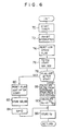
- the timer 11 is actuated, and at step 34 the state is kept. Under this condition, when the set time Td comes, the timer 11 generates the TINT pulse PT. In this case, the time interruption process (TINT process) of Fig. 5 is executed. In the time interruption process, first at step 40 the interruption is released from inhibition, and at step 42 the timer 11 is set to time Td and actuated. Then, at step 44 the low speed flag is set as shown in Fig. 7, and at step 46 the contents MB (1) is supplied from the counter 13 to the microprocessor 2. In Fig.
- the number within the parentheses following the count MB indicates the number of times the detection is made, and MB (n) represents a detected value at n-th detection.
- the program goes to step 50.
- the value is stored in a predetermined memory, ending the first process. If the motor is being driven as shown in Fig. 7, the program goes to step 56 where it is decided whether the contents MB (1) of the counter 13 exceeds a constant value M, or not. If it does not exceed, processes at steps 52 and 54 are executed.
- the pulse generator 5 generates no output pulse PL even while the motor is being driven as shown in Fig. 7, the process of Fig. 5 is executed at each time Td. As a result, the counter 13 is not reset, and thus the count MB becomes, for example, MB (3), exceeding the constant value M,. As a consequence, the program goes to step 58, where the pulse generator 5 is decided to be abnormal.
- the pulse generator 5 When the motor 4 is driven, the pulse generator 5 generates the output pulse PL. At this time, the microprocessor 2 is in the state at step 32 of Fig. 4, where the interruption is released from inhibit the NIN pulse made "1" level. Thus, the monostable circuit 15 generates the INT pulse PI in synchronism with the leading edges of the pulse PL. The microprocessor 2 executes the interruption process (INT process) of Fig. 6 when supplied with the INT pulse Pl.
- INT process interruption process
- the NIN pulse PN is made "1" level releasing the interruption from inhibition, and at step 42 the timer 11 is set to the time Td and actuated. Then, at step 44 the low speed flag is reset in the interruption process by the INT pulse PI, thus the program being progressed to step 60. At step 60, the low speed flag is again set, ending the process.
- Fig. 9 shows the speed calculation process from the time i at which the INT pulse PI is generated.
- the counts M, and M 2 of the pulse PL are calculated at step 88 from the counts MA (i+1) and MB (i+1) at time (i+1) as
- the speed detected value N f is determined by substitution of the calculated values M, and M 2 from Eqs. (2) and (3) into Eq. (1).
- the value N f calculated at step 90 is stored in a predetermined memory at step 86.
- a speed detecting circuit 6B in Fig. 11 the counter 13 is supplied as a reset pulse, with a logical sum of a reset pulse PR, from the microprocessor 2, and a pulse PR 2 which a monostable circuit 102 generates in synchronism with the leading edges of the output pulse PL from the pulse generator 5, through an OR circuit 104.
- a timer 104 is actuated by the output pulse (INT pulse) PI from the monostable circuit 15, and after lapse of a constant time Td, it generates the TINT pulse PT.
- FIG. 11 The operations of the arrangement of Fig. 11 will be described with reference to the flowcharts of Figs. 12 and 13 and the timing chart of Fig. 14.
- the flowcharts of Figs. 12 and 13 show the process for only detecting the speed stationarily, and the start and low speed process described in the embodiment of Fig. 3 are omitted therein.
- the microprocessor 2 executes the two processes of the interruption process by the INT pulse PI from the monostable circuit 15 and the time interruption process by the TINT pulse PI from the timer 100.
- the microprocessor 2 executes the interruption process of Fig. 13.
- the contents MA (i) of the counter 12 is supplied to the. microprocessor 2. Since the leading edges of the pulse PL at which the counter 12 counts up occur before the monostable circuit 15 generates the INT pulse PI, the count MA (i) supplied in the INT process includes the pulse PL at the time of generation of the INT pulse PI.
- the NIN pulse PN is made "0" level, inhibiting the INT pulse PI from generation.
- the INT pulse PI is supplied to the timer 100 as a trigger signal thereto.
- the timer 100 generates the TINT pulse PI the time Td after the INT pulse PI is supplied to the timer 100.
- the microprocessor 2 executes the TINT process of Fig. 15 when supplied with the TINT pulse.
- the microprocessor 2 receives the counts MA (i+1) and MB (i+1) from the counters 12 and 13 at time (i+1) at which the TINT pulse occurs.
- the count MA (i) received at time i in the INT process the above counts MA (i+1) and MB (i+1) are used for the calculation of the variation M, of the pulse PL from
- Eq. (1) is calculated by substituting the values M, and M 2 obtained from Eqs. (6) and (7), and at step 124 the speed detected value N f is stored in a memory to end the TINT process.
- the INT process and the TINT process as described above are repeatedly performed to detect the speed.
- the speed detected value is obtained with high resolution.
- the speed detecting time is constant, or Td
- the algorithm of the speed control computation having a relation with time for example, the process using integrating compensation can be performed simply.
- Fig. 15 shows another example of the speed detecting circuit of this invention.
- the start point of the set time Td is not in synchronism with the output pulse PL from the pulse generator 5 for detection of the speed.
- Fig. 15 The arrangement of Fig. 15 is different from that of Fig. 3 in that a timer 200 in a speed detecting circuit 6C generates the TINT pulse PT at each time Td.
- the time interruption process by the TINT pulse PT from the timer 200 has a priority lower than that of the interruption process by INT pulse PI. Therefore, the microprocessor 2 interrupts the execution of the time interruption process and executes the interruption prior thereto when supplied with the INT pulse PI.
- the microprocessor 2 performs the calculation of the speed detected values in the time interruption process and it is supplied with data necessary for the time interruption process and executes the preliminary computation in the interruption process.
- the microprocessor 2 executes the TINT process as shown in Fig. 16.
- the NIN pulse PN is made "0" level, inhibiting the INT pulse PI from interrupting, and at step 204, the counts MA (n) and MB (n) of the counters 12 and 13 are supplied to the microprocessor 2.
- the flag is set which decides that the first INT pulse PI has been generated after the INT pulse PT occured.
- the NIN pulse is made "1" level, releasing the interruption from the inhibition.
- the TINT process is executed, but when the INT pulse PI occurs, the INI process of Fig. 17 is executed.
- the count, MB n-1 (k) at time n-1 (k) at which the INT pulse PI occurs just before n-time point is subtracted from the count MB (n) of the counter (13).
- the generation time point n-1(k) is a time point at which the k-th pulse PL occurs after the TINT pulse PT was generated at n-1 time point.
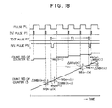
- the value, AMB 2 (n) determined at step 210 is the time interval between the TINT pulse PT occurring at n-time point and the leading edge of the pulse PL generated just therebefore, and is proportional to time ⁇ T 5 in Fig. 1.
- the value M is determined by subtracting 1 of pulse PL from the difference between the count MA (n) of the counter 12 at n-time point and the count MA (n-1) at time-point n-1. The subtraction of 1 pulse PL is necessary because the count MA (n-1) at (n-1)-time point includes a value of 1 which is counted out of the set time Td.
- the value M 2 is determined by substituting the counts MB (n) and MB (n-1) of the counter 13, the value ⁇ MB 2 (n) at step 210, and ⁇ MB 1 (n-1) determined by the INT process which will be described later, into the equation (8),
- the value M 2 obtained from Eq. (8) is a value proportional to the time Tdo as shown in Fig. 18.
- the speed N f is calculated by using the values M 1 and M 2 , and at step 217 the speed detected value N, is stored.
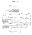
- the microprocessor 2 executes the INT process of Fig. 17.
- the count MB of the counter 13 is supplied to the microprocessor 2, and at step 220, the decision is made of the state of the flag of the INT pulse PI.
- the flag of the INT pulse is set by the TINT process of Fig. 16 if the INT pulse PI is the first one after the TINT pulse PT was generated. If the INT pulse is the first one after the TINT pulse PT was generated at n-time point, the flag is set, and at step 222 the value ⁇ MB 1 (n) is determined from the equation (9),
- the ⁇ MB 1 (n) in Eq. (9) is a value proportional to the time ⁇ T 3 in method D in Fig. 1. This value ⁇ MB t (n) is stored for use in the calculation of speed by the for method F Further explanation thereof will be omitted.
- the speed detecting time is substantially constant as time Td, and in the steady state in which the motor speed does not almost change, it is necessary to prolong the speed detecting time to improve the precision of speed detection.
- the speed detected value N f (m) is computed, where m represents a number of order.
- the previous detected value N fo (m-1) is subtracted from the m-th value.
- the final speed detected value is represented by N fo , and N f represents the result obtained by the computation at step 90. If TINT pulse at time n+1.
- the difference value MB, (n-1) between the counts of the counter 13 at the TINT pulse of time n-1 and the first INT pulse PI just thereafter.
- the methods E and F in Fig. 1 can be executed likewise by determining the values M, and M 2 in the embodiment of Fig. 15 from the following expression; for method E exceeds a preselected speed change setting value ⁇ N o , the step 134 and the followings are performed.
- the value ⁇ N o is selected to be desirably about the maximum value of the variation of the speed detected value N f measured at each Td+ ⁇ T 1 when the motor is rotated at a constant speed.
- step 134 I becomes 1, and thus the program goes to step 142.
- step 142 I is made 2 and SM 1 and SM 2 are calculated at steps 144 and 146. Since the SM 1 and SM 2 include M 1 (m-1) and M 2 (m-1) at time m-1 at step 136, the new SM 1 and SM 2 are the sum of the second counts and those values. In other words, the detecting time is extended to about 2Td.
- step 148 the speed detected value N fo is calculated.
- the detecting time is extended to 3Td, 4Td, 5Td, respectively thus detection precision being improved.
- the program goes to step 150, and steps 152 and 154 are executed. This is because the detecting time is limited to I o Td (here, 5Td). Therefore, the counts M 1 (m-I o ), M 2 (M-I o ), 1 0 times before are subtracted from the counts M 1 (m), M 2 (m) at this time and values M 1 (m), M 2 (m) are added thereto, respectively.
- the speed detected values N fo (m+4) and so on at time m+4 and the followings are obtained at steps 150 to 154.
- the speed detecting time is extended thereby improving the precision of detection.
- the program goes to steps 134 to 138, and therefore the response for the speed detection is never lost.
- the speed detecting time is extended when the change of the speed detected value is below a preset value
- the detection precision can be improved even if the speed detecting time is extended when the speed detected value is small or when the speed control devision is small.
- the process at step 132 is designed to be each algorithm.
- the speed detection using the output pulse from the pulse generator can be performed with good resolution and precision even if the speed changes.
Landscapes
- Physics & Mathematics (AREA)
- General Physics & Mathematics (AREA)
- Control Of Electric Motors In General (AREA)
- Linear Or Angular Velocity Measurement And Their Indicating Devices (AREA)
Claims (2)
Applications Claiming Priority (2)
| Application Number | Priority Date | Filing Date | Title |
|---|---|---|---|
| JP29271/81 | 1981-02-28 | ||
| JP56029271A JPS57144465A (en) | 1981-02-28 | 1981-02-28 | Speed detecting method |
Publications (2)
| Publication Number | Publication Date |
|---|---|
| EP0059433A1 EP0059433A1 (de) | 1982-09-08 |
| EP0059433B1 true EP0059433B1 (de) | 1988-07-27 |
Family
ID=12271612
Family Applications (1)
| Application Number | Title | Priority Date | Filing Date |
|---|---|---|---|
| EP82101446A Expired EP0059433B1 (de) | 1981-02-28 | 1982-02-25 | Vorrichtung zur Geschwindigkeitsermittlung |
Country Status (4)
| Country | Link |
|---|---|
| US (1) | US4584528A (de) |
| EP (1) | EP0059433B1 (de) |
| JP (1) | JPS57144465A (de) |
| DE (1) | DE3278823D1 (de) |
Families Citing this family (31)
| Publication number | Priority date | Publication date | Assignee | Title |
|---|---|---|---|---|
| JPS5913957A (ja) * | 1982-07-15 | 1984-01-24 | Fanuc Ltd | 速度検出回路 |
| JPS59155715A (ja) * | 1983-02-25 | 1984-09-04 | Hitachi Ltd | デイジタル式多軸位置、速度検出装置 |
| WO1984004415A1 (en) * | 1983-04-27 | 1984-11-08 | Helge Skovgaard | An apparatus for recording the speed of a vehicle |
| JPH0627653B2 (ja) * | 1983-11-08 | 1994-04-13 | 株式会社日立製作所 | 位置、速度検出方法及び装置 |
| JPS60216262A (ja) * | 1984-04-12 | 1985-10-29 | Hitachi Ltd | 位置,速度検出装置 |
| US4672556A (en) * | 1984-09-17 | 1987-06-09 | Sundstrand Corporation | Frequency detector system |
| AU5952186A (en) * | 1985-05-28 | 1986-12-24 | Emkay Manufacturing Co. | High speed digital frequency counter |
| JPS6281570A (ja) * | 1985-10-04 | 1987-04-15 | Mitsubishi Electric Corp | 速度検出装置 |
| US5170365A (en) * | 1985-12-12 | 1992-12-08 | General Electric Company | Propeller speed and phase sensor |
| GB2184305B (en) * | 1985-12-12 | 1990-03-21 | Gen Electric | Propeller speed measurement |
| JPS62162968A (ja) * | 1986-01-13 | 1987-07-18 | Hitachi Ltd | 速度検出装置 |
| JPH0788896B2 (ja) * | 1986-08-11 | 1995-09-27 | アイシン・エィ・ダブリュ株式会社 | 誤変速防止機能を備えた自動変速機 |
| US4885710A (en) * | 1987-06-25 | 1989-12-05 | Delco Electronics Corporation | Method and apparatus for low speed estimation |
| FR2618560B1 (fr) * | 1987-07-20 | 1989-11-17 | Commissariat Energie Atomique | Dispositif pour determiner les valeurs des vitesses instantanees d'un objet mobile |
| US4884227A (en) * | 1987-12-11 | 1989-11-28 | Toyota Jidosha Kabushiki Kaisha | Speed detecting apparatus for a vehicle |
| US4939659A (en) * | 1988-01-15 | 1990-07-03 | Allied-Signal, Inc. | Speed/rpm transmitting device |
| JPH0715482B2 (ja) * | 1988-04-15 | 1995-02-22 | 住友電気工業株式会社 | 回転速度の計測方法及び装置 |
| EP0367865B1 (de) * | 1988-11-11 | 1992-03-04 | Siemens Aktiengesellschaft | Verfahren zur Bestimmung des Messwertes einer Geschwindigkeit oder Drehzahl eines Objektes |
| US5112191A (en) * | 1989-04-11 | 1992-05-12 | General Electric Company | Rotating cowling |
| US5027298A (en) * | 1989-06-29 | 1991-06-25 | Genrad, Inc. | Low-dead-time interval timer |
| JPH04233467A (ja) * | 1990-12-14 | 1992-08-21 | Samsung Electron Co Ltd | モータの速度測定方法及びその装置 |
| US5097490A (en) * | 1991-01-14 | 1992-03-17 | Sundstrand Data Control, Inc. | Apparatus and method for improving the resolution with which a test signal is counted |
| US5323437A (en) * | 1992-09-16 | 1994-06-21 | Honeywell Inc. | Full and partial cycle counting apparatus and method |
| WO1995002827A1 (en) * | 1993-07-16 | 1995-01-26 | I-Stat Corporation | Automatic test parameters compensation of a real time fluid analysis sensing device |
| DE19530677A1 (de) * | 1995-08-21 | 1997-02-27 | Siemens Ag | Verfahren zur Geschwindigkeits- oder Drehzahlmessung |
| GB2328749B (en) * | 1997-08-29 | 2001-05-09 | Tvi Europ Ltd | A method for calibrating a speed or distance measuring device |
| US6219624B1 (en) | 1998-08-03 | 2001-04-17 | Visteon Global Technologies, Inc. | Synchronous timer vehicle speed measurement |
| DE19918542A1 (de) * | 1999-04-23 | 2000-10-26 | Zahnradfabrik Friedrichshafen | Vorrichtung zum genauen Messen der Drehzahl eines rotierenden Bauteils |
| US6831431B1 (en) | 1999-09-22 | 2004-12-14 | Papst-Motoren Gmbh & Co. Kg | Method for regulating the rotational speed of a motor and a motor for carrying out a method of this type |
| ATE383581T1 (de) | 1999-09-22 | 2008-01-15 | Ebm Papst St Georgen Gmbh & Co | Verfahren zur messung einer frequenzinformation, insbesondere einer drehzahlinformation bei einem motors, und vorrichtung zur durchführung eines solchen verfahrens |
| US10250241B2 (en) * | 2015-01-15 | 2019-04-02 | Infineon Technologies Ag | Asynchronous output protocol |
Family Cites Families (14)
| Publication number | Priority date | Publication date | Assignee | Title |
|---|---|---|---|---|
| US3524131A (en) * | 1967-09-25 | 1970-08-11 | John A Mcwaid | High speed frequency computing apparatus |
| JPS5325265B1 (de) * | 1971-06-15 | 1978-07-26 | ||
| DE2220878C3 (de) * | 1972-04-28 | 1982-04-22 | Philips Patentverwaltung Gmbh, 2000 Hamburg | Schaltungsanordnung zur digitalen Frequenzmessung |
| JPS49122382A (de) * | 1973-03-22 | 1974-11-22 | ||
| DE2353038A1 (de) * | 1973-10-23 | 1975-04-30 | Teldix Gmbh | Verfahren und anordnung zur messung der impulsfolgefrequenz einer impulsfolge |
| SE378037B (de) * | 1973-11-22 | 1975-08-11 | Asea Ab | |
| SU610021A1 (ru) * | 1976-11-09 | 1978-06-05 | Пермский политехнический институт | Цифровой измеритель скорости вращени |
| JPS5395676A (en) * | 1977-02-01 | 1978-08-22 | Toshiba Corp | Speed measuring system |
| DE2730699A1 (de) * | 1977-07-07 | 1979-01-18 | Vdo Schindling | Einrichtung zur anzeige einer mechanischen messgroesse, insbesondere der geschwindigkeit eines kraftfahrzeugs |
| US4128892A (en) * | 1977-09-07 | 1978-12-05 | Fairchild Camera And Instrument Corporation | Pulse width measurement circuitry |
| DE2842450C2 (de) * | 1978-09-29 | 1982-08-19 | MITEC Moderne Industrietechnik GmbH, 8012 Ottobrunn | Verfahren zur Messung der zeitlichen Abstände von jeweils zwei elektrischen Signalen |
| DE2902815A1 (de) * | 1979-01-25 | 1980-08-07 | Bosch Gmbh Robert | Vorrichtung zum erfassen der drehzahl und der drehzahlschwankungen einer welle, insbesondere der kurbelwelle einer brennkraftmaschine |
| JPS55160859A (en) * | 1979-06-04 | 1980-12-15 | Hitachi Ltd | Method for detecting speed of vehicle |
| US4355279A (en) * | 1980-12-29 | 1982-10-19 | Hewlett-Packard Company | Means and method for velocity decoding |
-
1981
- 1981-02-28 JP JP56029271A patent/JPS57144465A/ja active Pending
-
1982
- 1982-02-25 US US06/352,083 patent/US4584528A/en not_active Expired - Lifetime
- 1982-02-25 DE DE8282101446T patent/DE3278823D1/de not_active Expired
- 1982-02-25 EP EP82101446A patent/EP0059433B1/de not_active Expired
Also Published As
| Publication number | Publication date |
|---|---|
| EP0059433A1 (de) | 1982-09-08 |
| DE3278823D1 (en) | 1988-09-01 |
| JPS57144465A (en) | 1982-09-07 |
| US4584528A (en) | 1986-04-22 |
Similar Documents
| Publication | Publication Date | Title |
|---|---|---|
| EP0059433B1 (de) | Vorrichtung zur Geschwindigkeitsermittlung | |
| US5041979A (en) | Bounded synchronous angle counter | |
| US4814704A (en) | Rotor position indicator with correction for apparant acceleration and deceleration | |
| US4667297A (en) | Running speed detector | |
| US4975642A (en) | Method of and apparatus for measuring revolution speed in response to pulse signals detected from a rotary member | |
| GB2065939A (en) | Arrangement having a programmabel electrical circuit and monitoring menas | |
| JP2539940B2 (ja) | 高効率回転速度計算法 | |
| EP0162268A1 (de) | Verfahren und Vorrichtung zur Stellungs-/Geschwindigkeitsermittlung | |
| EP0409185B1 (de) | Verfahren zur Berechnung der Regelspannung und Motorregelvorrichtung, die dieses Verfahren anwendet | |
| EP0310823A2 (de) | Synchroner Winkelzähler | |
| US5130626A (en) | Device for controlling rotational speed of motor | |
| JPH027276B2 (de) | ||
| US4991100A (en) | Method for computing a value of speed from a pulse signal | |
| EP0137304B1 (de) | Farbsynchronsignalgenerator | |
| JPS54147882A (en) | Abnormality occurrence detecting method of rotating machine using acoustic signals | |
| JP2712045B2 (ja) | 回転速度計測装置 | |
| JPH0340847B2 (de) | ||
| US3681780A (en) | Method for automatically detecting the presence of cyclic pulses in noise corrupted process measurements | |
| JP2670162B2 (ja) | モータの回転速度制御装置 | |
| JP2781232B2 (ja) | モータ制御装置における定常域到達検出装置 | |
| JPH0329986B2 (de) | ||
| JP3049671B2 (ja) | 直流電動機の速度制御装置 | |
| JP2735324B2 (ja) | モータの回転速度制御装置 | |
| Tso et al. | Software realisation of synchronisation and firing control of thyristor convertors | |
| JPH0519107B2 (de) |
Legal Events
| Date | Code | Title | Description |
|---|---|---|---|
| PUAI | Public reference made under article 153(3) epc to a published international application that has entered the european phase |
Free format text: ORIGINAL CODE: 0009012 |
|
| AK | Designated contracting states |
Designated state(s): CH DE SE |
|
| 17P | Request for examination filed |
Effective date: 19830127 |
|
| KL | Correction list |
Free format text: 83/02 |
|
| GRAA | (expected) grant |
Free format text: ORIGINAL CODE: 0009210 |
|
| AK | Designated contracting states |
Kind code of ref document: B1 Designated state(s): CH DE LI SE |
|
| REF | Corresponds to: |
Ref document number: 3278823 Country of ref document: DE Date of ref document: 19880901 |
|
| PLBE | No opposition filed within time limit |
Free format text: ORIGINAL CODE: 0009261 |
|
| STAA | Information on the status of an ep patent application or granted ep patent |
Free format text: STATUS: NO OPPOSITION FILED WITHIN TIME LIMIT |
|
| 26N | No opposition filed | ||
| EAL | Se: european patent in force in sweden |
Ref document number: 82101446.1 |
|
| PGFP | Annual fee paid to national office [announced via postgrant information from national office to epo] |
Ref country code: CH Payment date: 19980120 Year of fee payment: 17 |
|
| PG25 | Lapsed in a contracting state [announced via postgrant information from national office to epo] |
Ref country code: LI Free format text: LAPSE BECAUSE OF NON-PAYMENT OF DUE FEES Effective date: 19990228 Ref country code: CH Free format text: LAPSE BECAUSE OF NON-PAYMENT OF DUE FEES Effective date: 19990228 |
|
| REG | Reference to a national code |
Ref country code: CH Ref legal event code: PL |
|
| PGFP | Annual fee paid to national office [announced via postgrant information from national office to epo] |
Ref country code: SE Payment date: 20001227 Year of fee payment: 20 |
|
| PGFP | Annual fee paid to national office [announced via postgrant information from national office to epo] |
Ref country code: DE Payment date: 20010330 Year of fee payment: 20 |
|
| EUG | Se: european patent has lapsed |
Ref document number: 82101446.1 |