EP0059877A1 - Accouplement pour tuyaux à pression - Google Patents
Accouplement pour tuyaux à pression Download PDFInfo
- Publication number
- EP0059877A1 EP0059877A1 EP82101367A EP82101367A EP0059877A1 EP 0059877 A1 EP0059877 A1 EP 0059877A1 EP 82101367 A EP82101367 A EP 82101367A EP 82101367 A EP82101367 A EP 82101367A EP 0059877 A1 EP0059877 A1 EP 0059877A1
- Authority
- EP
- European Patent Office
- Prior art keywords
- retaining ring
- plug
- coupling according
- receiving part
- area
- Prior art date
- Legal status (The legal status is an assumption and is not a legal conclusion. Google has not performed a legal analysis and makes no representation as to the accuracy of the status listed.)
- Granted
Links
- 230000008878 coupling Effects 0.000 title claims abstract description 35
- 238000010168 coupling process Methods 0.000 title claims abstract description 35
- 238000005859 coupling reaction Methods 0.000 title claims abstract description 35
- 230000007480 spreading Effects 0.000 claims description 7
- 238000003892 spreading Methods 0.000 claims description 7
- 239000004033 plastic Substances 0.000 claims description 4
- 230000003313 weakening effect Effects 0.000 claims description 4
- 210000000056 organ Anatomy 0.000 claims description 3
- 229920005176 Hostaform® Polymers 0.000 claims 1
- 229920001577 copolymer Polymers 0.000 claims 1
- -1 polymethylene Polymers 0.000 claims 1
- 230000008901 benefit Effects 0.000 description 6
- 238000007789 sealing Methods 0.000 description 6
- 230000000694 effects Effects 0.000 description 2
- 238000003780 insertion Methods 0.000 description 2
- 230000037431 insertion Effects 0.000 description 2
- 238000004519 manufacturing process Methods 0.000 description 2
- 239000000463 material Substances 0.000 description 2
- 239000012815 thermoplastic material Substances 0.000 description 2
- XLYOFNOQVPJJNP-UHFFFAOYSA-N water Substances O XLYOFNOQVPJJNP-UHFFFAOYSA-N 0.000 description 2
- 230000009471 action Effects 0.000 description 1
- 230000009286 beneficial effect Effects 0.000 description 1
- 210000000078 claw Anatomy 0.000 description 1
- 238000010276 construction Methods 0.000 description 1
- 238000009826 distribution Methods 0.000 description 1
- 238000002347 injection Methods 0.000 description 1
- 239000007924 injection Substances 0.000 description 1
- 238000003754 machining Methods 0.000 description 1
- 230000035515 penetration Effects 0.000 description 1
- 230000002093 peripheral effect Effects 0.000 description 1
- 239000007787 solid Substances 0.000 description 1
- 230000007704 transition Effects 0.000 description 1
Images




Classifications
-
- F—MECHANICAL ENGINEERING; LIGHTING; HEATING; WEAPONS; BLASTING
- F16—ENGINEERING ELEMENTS AND UNITS; GENERAL MEASURES FOR PRODUCING AND MAINTAINING EFFECTIVE FUNCTIONING OF MACHINES OR INSTALLATIONS; THERMAL INSULATION IN GENERAL
- F16L—PIPES; JOINTS OR FITTINGS FOR PIPES; SUPPORTS FOR PIPES, CABLES OR PROTECTIVE TUBING; MEANS FOR THERMAL INSULATION IN GENERAL
- F16L27/00—Adjustable joints; Joints allowing movement
- F16L27/08—Adjustable joints; Joints allowing movement allowing adjustment or movement only about the axis of one pipe
- F16L27/0804—Adjustable joints; Joints allowing movement allowing adjustment or movement only about the axis of one pipe the fluid passing axially from one joint element to another
- F16L27/0808—Adjustable joints; Joints allowing movement allowing adjustment or movement only about the axis of one pipe the fluid passing axially from one joint element to another the joint elements extending coaxially for some distance from their point of separation
- F16L27/0812—Adjustable joints; Joints allowing movement allowing adjustment or movement only about the axis of one pipe the fluid passing axially from one joint element to another the joint elements extending coaxially for some distance from their point of separation with slide bearings
- F16L27/0816—Adjustable joints; Joints allowing movement allowing adjustment or movement only about the axis of one pipe the fluid passing axially from one joint element to another the joint elements extending coaxially for some distance from their point of separation with slide bearings having radial sealing
-
- B—PERFORMING OPERATIONS; TRANSPORTING
- B60—VEHICLES IN GENERAL
- B60T—VEHICLE BRAKE CONTROL SYSTEMS OR PARTS THEREOF; BRAKE CONTROL SYSTEMS OR PARTS THEREOF, IN GENERAL; ARRANGEMENT OF BRAKING ELEMENTS ON VEHICLES IN GENERAL; PORTABLE DEVICES FOR PREVENTING UNWANTED MOVEMENT OF VEHICLES; VEHICLE MODIFICATIONS TO FACILITATE COOLING OF BRAKES
- B60T17/00—Component parts, details, or accessories of power brake systems not covered by groups B60T8/00, B60T13/00 or B60T15/00, or presenting other characteristic features
- B60T17/04—Arrangements of piping, valves in the piping, e.g. cut-off valves, couplings or air hoses
-
- F—MECHANICAL ENGINEERING; LIGHTING; HEATING; WEAPONS; BLASTING
- F16—ENGINEERING ELEMENTS AND UNITS; GENERAL MEASURES FOR PRODUCING AND MAINTAINING EFFECTIVE FUNCTIONING OF MACHINES OR INSTALLATIONS; THERMAL INSULATION IN GENERAL
- F16L—PIPES; JOINTS OR FITTINGS FOR PIPES; SUPPORTS FOR PIPES, CABLES OR PROTECTIVE TUBING; MEANS FOR THERMAL INSULATION IN GENERAL
- F16L37/00—Couplings of the quick-acting type
- F16L37/008—Couplings of the quick-acting type for branching pipes; for joining pipes to walls
-
- Y—GENERAL TAGGING OF NEW TECHNOLOGICAL DEVELOPMENTS; GENERAL TAGGING OF CROSS-SECTIONAL TECHNOLOGIES SPANNING OVER SEVERAL SECTIONS OF THE IPC; TECHNICAL SUBJECTS COVERED BY FORMER USPC CROSS-REFERENCE ART COLLECTIONS [XRACs] AND DIGESTS
- Y10—TECHNICAL SUBJECTS COVERED BY FORMER USPC
- Y10S—TECHNICAL SUBJECTS COVERED BY FORMER USPC CROSS-REFERENCE ART COLLECTIONS [XRACs] AND DIGESTS
- Y10S285/00—Pipe joints or couplings
- Y10S285/921—Snap-fit
Definitions
- the invention relates to a coupling for a pressure line, in particular for the connection of compressed air lines to organs of a compressed air brake of a motor vehicle, with a plug-in part with a through hole, a receiving part with a through hole and external thread that can be screwed into a threaded hole and an elastic, expandable retaining ring that engages positively in the plug-in part and the receiving part and thereby fixes these parts in the axial direction relative to one another.
- Plug connections have the advantage over screw connections that the connection of lines is made considerably easier, since instead of an often tedious and time-consuming screwing in in places that are sometimes difficult to access, a single handle is sufficient to connect a pressure line.
- Plug connections of the type mentioned are already known (DE-OS 28 56 069), in which the receiving part is designed as an adapter, which allows plug connections to be made to such organs, e.g. Brake cylinders to connect, which have a standardized threaded hole for a screw connection.
- the retaining ring is located near the rear end of the receiving part, which results in a relatively large overall length of the coupling.
- the invention has for its object to design a coupling of the type mentioned so that the smallest possible length is achieved.
- the retaining ring is arranged at the front end of the receiving part, is positively fixed to it in the axial direction, engages over the front end face of the receiving part and engages in an outer groove of the plug-in part.
- the plug-in part extends through the receiving part over its entire length and is locked to the receiving part at its front end. This gives the desired long guide length for the plug-in part without the receiving part having to protrude significantly beyond the rear end of the threaded hole.
- the receiving part can therefore be designed in such a way that only an area with wrench flats, generally hexagonal, protrudes outside the threaded bore.
- the form-fitting fixation of the retaining ring in the receiving part can be done in different ways. Examples of this are given in claims 2 to 6.
- the embodiments according to claims 2 and 6 have the advantage that the receiving part is a simple turned part on which no machining is required except for turning operations.
- the embodiments according to claims 4 and 5, on the other hand, have the advantage that the clear width of the plug-in part can be kept very large, since the diameter range which is occupied by a wall which must be located at the bottom of a closed groove is saved.
- the embodiment according to claim 7 is particularly advantageous since it offers additional security against unintentional detachment of the plug-in part.
- the retaining ring namely, due to its support on the threaded bore, it cannot expand to such an extent that it can migrate out of the outer groove of the receiving part or out of the outer groove of the plug-in part. It is particularly expedient to design the outer diameter of the retaining ring approximately equal to the inner diameter of the threaded bore.
- a cheap element namely an elastic sealing ring, is used for the axial bracing of the locking device and at the same time has the effect that the penetration of dirt into the gap area of the coupling is avoided, i.e. in the area in which the plug-in part protrudes into the receiving part.
- a seal preferably arranged there is therefore not endangered by dirt.
- a particularly efficient seal is obtained with a seal shape and a shape for the recess in which the seal is located, as specified in claims 10 and 11.
- the embodiment according to claim 12 has the advantage that the plug-in part can be held when the receiving part is unscrewed. You can avoid twisting of the hose connected to the plug-in part even if the plug-in part is stuck in the receiving part, e.g. by the action of splash water, especially salty splash water.
- a particularly advantageous embodiment of the retaining ring is specified in claims 13 to 18.
- Spreading surfaces according to claim 13 facilitate the expansion of the retaining ring.
- Spreading surfaces are preferably arranged both on the plug-in part and on the retaining ring; However, this is not mandatory, since spreading areas on only one part already facilitate the spreading.
- the cross-sectional shape specified in claim 14 facilitates spreading, since the ring in the area in which it is to be expanded, is relatively compliant.
- a slot according to claim 15 allows the insertion of the retaining ring in the receiving part with little deformation of the retaining ring.
- a predetermined breaking point can also be provided according to claim 16, which is only broken open, for example by means of a screwdriver, when the retaining ring is removed from the receiving part should be removed.
- Resilient segments are formed by weakening notches according to claim 17, which enable the plug-in part to be inserted with relatively little effort.
- the retaining ring can be made of different materials.
- Thermoplastic materials are particularly well suited, e.g. the plastic specified in claim 18.
- the use of thermoplastic material also permits the production of the retaining ring as a plastic injection-molded part, which type of production is particularly efficient.
- the main components of the coupling have a plug-in part 1, a receiving portion 2 and a retainer ring 3.
- the receiving part 3 is screwed into a body 4, for example in the case of a B Rems cylinder.
- the plug-in part 1 has a tube extension 5 for attaching a hose 6 indicated by dash-dotted lines.
- the tube extension is provided in a known manner with circumferential ribs 7 which have a barbed cross-section, thereby preventing the hose 6 from slipping off.
- a flange 8 Below the tube extension 5 there is a flange 8, the lower surface 8a of which presses on an elastic sealing ring 9 in the assembled state of the coupling.
- a fitting area 10 Below the flange 8 there is a fitting area 10, which has a cylindrical outer surface 10a which fits in a cylindrical bore 11 of the receiving part 2.
- an outer groove 12 In the fitting area 10 there is an outer groove 12, in which a sealing ring 13 is received, which lies sealingly against the bore wall 11.
- the plug-in part 1 At the lower end of the fitting area 10 there is an external groove 14 on the plug-in part, into which the retaining ring 3 engages in the assembled state. Below the outer groove, the plug-in part 1 has a conical surface 15 which converges towards the front (the end surface 16 of the plug-in part should be the front end surface).
- the plug-in part has a through bore 17, the inside width of which is approximately the same as the inside width of the hose 6.
- the receiving part 2 has a screw-in area 18 which is provided with an external thread 19.
- a flange 20 of relatively large thickness adjoins the screw-in area 18, the outer surfaces 20a of which are key surfaces forms, namely as a hexagon.
- the screw-in part 2 has at its rear end (the upper end surface 23 should be the rear end surface) a large recess 24 in which the already mentioned elastic sealing ring 9 is seated. It rests on the lower surface 24a and on the peripheral surface 24b of the recess. On the other hand, it bears on the already mentioned lower surface 8a of the flange 8 and on a cylindrical surface 25 which is located on the plug-in part between the flange 8 and the fitting area 10.
- annular groove 26 In the vicinity of the front end of the receiving part 2 there is an annular groove 26 into which the retaining ring 3 engages.
- the groove 26 is separated from the front end face 27 of the receiving part 2 by a wall 28 which has a diameter d w .
- the diameter d is naturally larger than the diameter d of the bottom of the groove 26.
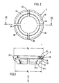
- the retaining ring 3 is a plastic injection molded part that consists of one piece.
- the cross section can be divided into a holding area 29, a constriction area 30 and a locking area 31.
- the holding area 29 has a cylindrical outer wall 32 with a diameter d H.
- the locking region 31 has a front flat end face 31a which is intended to cooperate with the front wall 14a of the outer groove of the plug-in part.
- On the locking part 31 there is also a conical surface 31b which is convergent towards the front and serves as an insertion bevel.
- the inside diameter d E of the constriction area 30 is larger than the outside diameter d W of the groove wall 28.
- the locking region 31 has a shape which converges towards the front, that is to say towards the end surface 31a.
- the inner diameter of the retaining ring at its narrowest point is d. designated.
- the plug-in part has a diameter d below the outer groove 1-4, which is equal to the diameter in the fitting area 10.
- the diameter could also be somewhat smaller, but in no case larger than this diameter.
- the retaining ring has a radial slot 34 that completely separates it and three weakening notches 35, 36 and 37.
- the weakening notches 36 sever the locking region 31 and the constriction region 30, but do not cut the holding region 29.
- the ring is divided into four segments 38, 39, 40 and 41 in its locking region 31. These segments are relatively easy to bend outwards since they are only connected to the holding area 29 via the thin constriction area 30.
- the coupling works as follows. First, the receiving part 2 is screwed into a threaded bore 42 of the body 4.
- This threaded hole can be a standardized hole.
- the sealing ring 22 seals against the surface 4a of the body 4.
- the retaining ring 3 is already connected to the receiving part 2. The connection was made by spreading the retaining ring, which is easily possible thanks to the cut at slot 24. Thereafter, the ring can be slipped over the diameter d W of the wall 28. Due to its inherent elasticity, the holding area 29 is snapped into the groove 26. Since the outer diameter d H of the holding area 29 is somewhat smaller than the inner diameter d G of the threaded hole 42, it has not hindered the screwing onto the receiving part.
- the plug-in part can now be installed by simply plugging it in.
- the seals 13 and 9 are held captively on the plug-in part. If the plug-in part is now inserted in the receiving part 2 is inserted, the orientation of the fitting zone 10 is in the bore 11 facilitated by the conical surface 15 on the plug-in part and a further conical transition surface 4.3 on the receiving part 2.
- the retainer ring 3 is then spread characterized in that the conical surface 15 of conical S teckvons at the Surface 31b of the retaining ring comes into contact and bends the four segments 38, 39, 40 and 41.
- the coupling can only be released by unscrewing the receiving part 2.
- the retaining ring In the unscrewed state, the retaining ring is no longer prevented from widening, so that it can be widened to such an extent that the segments 38 to 41 can be pulled out of the groove 14.
- connection hole is shown in the right half, as is usual for screw connections.
- This bore has a bottom 42a.
- the coupling is also suitable for screwing into relatively thin walls 44, namely walls whose thickness s is at least so great that the holding area 29 of the retaining ring 3 can still be supported on the bore wall.
- the plug-in part 1 can also be rotated relative to the receiving part 2 after the coupling. This is of particular interest if the plug-in part is angular. Of course, such designs also fall within the scope of the invention.
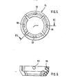
- FIGS. 4 to 6 differs from the embodiment of the Fi g. 1 to 3 with regard to the nature of the upper sealing ring (designated 9 in Fig. 1) and with regard to the fastening of the retaining ring.
- 4 has a rectangular cross section in the relaxed state (the tensioned state is shown in FIG. 4). When the plug-in part is inserted, the seal is slightly compressed and then takes the form. 4 a.
- the seal 50 engages in a recess designated 51 overall.
- This recess has a flat bottom 51a, a hollow cylindrical section 51b and a hollow conical section 51c.
- the diameter of the section 51a is dimensioned such that the outer surface of the seal 50 lies against the cylinder wall.
- the inner wall of the seal 50 bears against a cylindrical outer surface 52 of the plug-in part S 1 .
- a further difference from the exemplary embodiment according to FIGS. 1 to 3 is that the surface 53a on which the seal 50 rests is formed by a collar 53 which has key surfaces 53b on the outside, for example is designed as a hexagon.
- This has the advantage that the plug part S can be held when the receiving part A 1 is unscrewed. In this way, twisting of the hose 54 is avoided.
- the retaining ring denoted overall by H 1 , has a total of four lugs 55 to 58 on its inside, which protrude inwards. These lugs engage in four holes 59 which are located on the receiving part A 1 and which are located at this point fully reach through the reduced wall of the receiving part.
- the advantage is achieved that the inside width d of the plug-in part S 1 can be made larger. This effect is based on the fact that the wall thickness can be eliminated, which in the embodiment according to FIGS. 1 to 3 must remain within the bottom of the outer groove 26.
- the plug-in part is denoted by S 2 ', the receiving part by A 2 and the retaining ring by H 2 .
- This embodiment differs from the embodiment according to FIGS. 4 to 6 in the manner in which the retaining ring H 2 is fastened.
- the retaining ring H 2 (see also FIGS. 8 and 9) has four webs 60 to 63 on its inside. These webs have flat surfaces 60a to 63a, these surfaces of adjacent webs being at right angles to one another. The webs are thus offset from each other by 90 °.
- the receiving part A 2 there are four corresponding grooves 64 in which the webs engage. Even with this construction, the clear width d L can be kept relatively large, since the straight grooves 64 can approach the inner diameter of the receiving part A 2 , since there is enough material left in the area between the grooves 64 to ensure the solid cohesion of the to ensure below the grooves 64 the area of the receiving part A 2 with the area above.
- the main parts are labeled S 3 , A 3 and H 3 .
- This embodiment differs from the embodiments according to FIGS. 4 to 9 in turn by the fastening of the retaining ring H 3 .
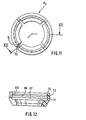
- the retaining ring H3 has three grooves 65, 66 and 67 on its inside. The grooves together form a sawtooth-like profile, which is oriented so that the retaining ring H 3 on the Slide on receiving part A 3 , but that it is difficult to pull off or is not possible at all without opening the retaining ring H 3 .
- grooves 68, 69 and 70 which correspond to the projections 71, 72 and 73 which are located on the holding part between the grooves 65, 66 and 67. These protrusions act like barbs that claw in the grooves 68, 69 and 70.
- the retaining ring H 3 is completely closed before and after assembly.
- a weakened connecting web 75 which is designed as a predetermined breaking point. If it is necessary to remove the retaining ring, the ring is broken by breaking the weakened web 75, whereby the retaining ring can be expanded to such an extent that it can be removed. Thereafter, further use of the retaining ring is no longer possible if the grooves 68, 69 and 70 are as flat as shown. The support of the retaining ring H 3 on the bore wall is then no longer sufficient to hold the projections 71, 72, 73 with the grooves 68, 69, 70 securely.
- the embodiment according to FIGS. 10 to 12 also has a relatively large clear width d L , since the distribution of the axial holding force over a plurality of grooves 68, 69, 70 makes them very flat.
Landscapes
- Engineering & Computer Science (AREA)
- General Engineering & Computer Science (AREA)
- Mechanical Engineering (AREA)
- Transportation (AREA)
- Quick-Acting Or Multi-Walled Pipe Joints (AREA)
Applications Claiming Priority (2)
| Application Number | Priority Date | Filing Date | Title |
|---|---|---|---|
| DE3108651A DE3108651C2 (de) | 1981-03-07 | 1981-03-07 | Kupplung für eine Druckleitung |
| DE3108651 | 1981-03-07 |
Publications (2)
| Publication Number | Publication Date |
|---|---|
| EP0059877A1 true EP0059877A1 (fr) | 1982-09-15 |
| EP0059877B1 EP0059877B1 (fr) | 1985-05-08 |
Family
ID=6126571
Family Applications (1)
| Application Number | Title | Priority Date | Filing Date |
|---|---|---|---|
| EP82101367A Expired EP0059877B1 (fr) | 1981-03-07 | 1982-02-24 | Accouplement pour tuyaux à pression |
Country Status (4)
| Country | Link |
|---|---|
| US (1) | US4448447A (fr) |
| EP (1) | EP0059877B1 (fr) |
| DE (2) | DE3108651C2 (fr) |
| ZA (1) | ZA821464B (fr) |
Cited By (6)
| Publication number | Priority date | Publication date | Assignee | Title |
|---|---|---|---|---|
| GB2171480A (en) * | 1985-02-26 | 1986-08-28 | Bendix Ltd | Quick-fit pipe coupling |
| US4696495A (en) * | 1985-02-26 | 1987-09-29 | Bendix Limited | Pipe fitting assembly |
| EP0256179A1 (fr) * | 1986-08-11 | 1988-02-24 | Bendix Limited | Assemblage de tuyauterie |
| GB2241032A (en) * | 1990-02-15 | 1991-08-21 | Ford Motor Co | Inserting a tube in a moulding wall using a self-tapping thread |
| CN105387249A (zh) * | 2014-08-28 | 2016-03-09 | 侨雄实业股份有限公司 | 打气枪及其气嘴连接器 |
| WO2019050461A1 (fr) * | 2017-09-08 | 2019-03-14 | Steelwrist Ab | Dispositif d'accouplement hydraulique et unités d'accouplement mâle et femelle |
Families Citing this family (35)
| Publication number | Priority date | Publication date | Assignee | Title |
|---|---|---|---|---|
| DE3313859A1 (de) * | 1982-06-16 | 1983-12-22 | Armaturenfabrik Hermann Voss GmbH + Co, 5272 Wipperfürth | Steckverbindung |
| US4516796A (en) * | 1983-03-28 | 1985-05-14 | The Estate Of Thomas S. Krause | Fluid coupling |
| DE3341030A1 (de) * | 1983-11-12 | 1985-05-23 | Armaturenfabrik Hermann Voss GmbH + Co, 5272 Wipperfürth | Verbindungsvorrichtung fuer druckleitungen mit unverlierbarem haltering |
| JPS63185988U (fr) * | 1987-05-23 | 1988-11-29 | ||
| US5050911A (en) * | 1990-01-05 | 1991-09-24 | Kaiser Aerospace & Electronics Corporation | Breakaway coupling |
| US5163716A (en) * | 1991-10-25 | 1992-11-17 | General Motors Corporation | Condenser connector assembly for connecting refrigerant line |
| NO943718D0 (no) * | 1994-10-05 | 1994-10-05 | Nodeco As | Overlastsikring |
| WO1997036128A1 (fr) * | 1996-03-25 | 1997-10-02 | Kunststoffröhren Sendenhorst Gmbh | Raccord pour canalisations en beton |
| GB2317931B (en) * | 1996-10-03 | 2000-05-31 | Rover Group | A Guide tube for a dipstick |
| DE19848489B4 (de) * | 1998-10-21 | 2006-01-26 | Johannes Schäfer vorm. Stettiner Schraubenwerke GmbH & Co. KG | Lösbare Steckverbindung für den Anschluß von Rohrleitungen |
| EP1033520B2 (fr) † | 1999-03-04 | 2010-05-26 | Johannes Schäfer vormals Stettiner Schraubenwerke GmbH & Co. KG | Raccord à emboîtement détachable pour la connexion de tuyaux |
| US6908117B1 (en) | 2000-10-06 | 2005-06-21 | Hutchinson Fts, Inc. | Block-conduit connection alignment device |
| WO2002073077A1 (fr) * | 2001-03-09 | 2002-09-19 | The Gates Corporation | Raccord rapide |
| WO2004105856A1 (fr) * | 2003-06-03 | 2004-12-09 | Mixpac Systems Ag | Dispositif pour raccorder une tubule a un melangeur |
| US20050109245A1 (en) * | 2003-11-21 | 2005-05-26 | Pote Michael J. | Cold table with open top |
| FR2881502B1 (fr) * | 2005-01-28 | 2007-03-30 | Legris Sa | Dispositif de raccordement auto-extractible |
| US7267374B2 (en) * | 2005-04-22 | 2007-09-11 | Saint-Gobain Performance Plastics Corporation | Swivel coupling |
| NL1029030C2 (nl) * | 2005-05-12 | 2006-11-14 | Actuant Corp | Hydraulisch systeem. |
| US8746751B2 (en) * | 2006-03-16 | 2014-06-10 | The Gates Corporation | Quick connect coupling systems with insert |
| JP2010185568A (ja) * | 2009-01-14 | 2010-08-26 | Smc Corp | 管継手 |
| US8960484B2 (en) | 2010-07-30 | 2015-02-24 | Ferus Inc. | Transport tank |
| US20130049358A1 (en) * | 2011-08-24 | 2013-02-28 | Brian P. Wolff | Threaded inline swivel |
| DE102011076800A1 (de) * | 2011-05-31 | 2012-12-06 | Behr Gmbh & Co. Kg | Wärmeübertrager |
| EP3332938B1 (fr) | 2012-07-02 | 2020-04-22 | Norma U.S. Holding LLC | Raccord de conduite de carburant, procédé de fabrication |
| US10473243B2 (en) * | 2016-01-26 | 2019-11-12 | Tectran Mfg. Inc. | Hose repair kit with live swivel coupling |
| US10697573B2 (en) * | 2017-06-27 | 2020-06-30 | Kenny Bassett | Plumbing fitting assembly for transverse hole in structure |
| US12608000B2 (en) | 2018-02-21 | 2026-04-21 | Outrider Technologies, Inc. | System and method for automated opening of trailer doors |
| US11707955B2 (en) | 2018-02-21 | 2023-07-25 | Outrider Technologies, Inc. | Systems and methods for automated operation and handling of autonomous trucks and trailers hauled thereby |
| EP4434776B1 (fr) * | 2018-02-21 | 2026-04-08 | Outrider Technologies, Inc. | Systèmes et procédés pour le fonctionnement et la manipulation automatisés de camions autonomes et remorques tirées par ceux-ci |
| US12246457B2 (en) | 2018-02-21 | 2025-03-11 | Outrider Technologies, Inc. | System and method for connection of service lines to trailer fronts by automated trucks |
| US12448063B2 (en) | 2018-02-21 | 2025-10-21 | Outrider Technologies, Inc. | Systems and methods for automated operation and handling of autonomous trucks and trailers hauled thereby |
| DE102018114918A1 (de) * | 2018-06-21 | 2019-12-24 | Norma Germany Gmbh | Verbindungsanordnung zum Ausbilden einer fluidführenden Verbindung |
| US11858491B2 (en) | 2018-10-30 | 2024-01-02 | Outrider Technologies, Inc. | System and method for controlling braking functions in an autonomous vehicle |
| US11118836B2 (en) * | 2019-07-10 | 2021-09-14 | Alexander Pavlovskiy | Reusable air injector for drywall |
| DE102021102585A1 (de) | 2021-02-04 | 2022-08-04 | Johannes Schäfer vorm. Stettiner Schraubenwerke GmbH & Co. KG | Steckverbindungen zum lösbaren Verbinden von Leitungen und System umfassend eine solche Steckverbindung |
Citations (5)
| Publication number | Priority date | Publication date | Assignee | Title |
|---|---|---|---|---|
| CH318678A (de) * | 1953-09-22 | 1957-01-15 | Beka St Aubin Ag | Beim Trennen der Kupplungshälften automatisch schliessende Kupplung für zwei ein flüssiges oder gasförmiges Medium führende Leitungen |
| DE1951902A1 (de) * | 1969-10-15 | 1971-04-22 | Phoenix Gummiwerke Ag | Elastisches Verbindungselement fuer Pressluftleitungen an Schienenfahrzeugen |
| DE1475792B2 (de) * | 1965-01-02 | 1973-06-14 | Parker Hannifin Corp , Cleveland, Ohio (V St A ) | Verfahren und hilfswerkzeug zur halterung eines dichtungshalterings auf einer umfangsnut eines einschraubnippels sowie dichtungshaltering zur verwendung beim verfahren |
| DE2853281A1 (de) * | 1977-12-23 | 1979-06-28 | Ford Werke Ag | Kupplung zum anschluss einer leitung an einen behaelter |
| DE2824943A1 (de) * | 1978-06-07 | 1979-12-20 | Voss Armaturen | Anschlussvorrichtung fuer bremsleitungen |
Family Cites Families (8)
| Publication number | Priority date | Publication date | Assignee | Title |
|---|---|---|---|---|
| GB173580A (en) * | 1920-09-27 | 1921-12-28 | William Carl Iftiger | An improved coupling |
| US1904061A (en) * | 1930-12-03 | 1933-04-18 | Larson Sigfrid | Hose coupling |
| FR909478A (fr) * | 1944-10-17 | 1946-05-09 | Raccord de tuyaux | |
| US3565467A (en) * | 1969-04-14 | 1971-02-23 | American Standard Inc | Spout connector apparatus |
| GB1413673A (en) * | 1972-06-26 | 1975-11-12 | Bunker Ramo | Push-pull connector |
| US4045055A (en) * | 1974-02-13 | 1977-08-30 | Olin Corporation | Quick-connect coupling |
| US4105226A (en) * | 1976-06-01 | 1978-08-08 | Celanese Corporation | Snap-in fittings and coupling ring therefor |
| IT1086546B (it) * | 1977-05-23 | 1985-05-28 | Uniflex Spa | Giunto per tubi flessibili ad aggancio e sgancio rapido |
-
1981
- 1981-03-07 DE DE3108651A patent/DE3108651C2/de not_active Expired
-
1982
- 1982-02-24 EP EP82101367A patent/EP0059877B1/fr not_active Expired
- 1982-02-24 DE DE8282101367T patent/DE3263638D1/de not_active Expired
- 1982-03-02 US US06/353,793 patent/US4448447A/en not_active Expired - Fee Related
- 1982-03-05 ZA ZA821464A patent/ZA821464B/xx unknown
Patent Citations (7)
| Publication number | Priority date | Publication date | Assignee | Title |
|---|---|---|---|---|
| CH318678A (de) * | 1953-09-22 | 1957-01-15 | Beka St Aubin Ag | Beim Trennen der Kupplungshälften automatisch schliessende Kupplung für zwei ein flüssiges oder gasförmiges Medium führende Leitungen |
| DE1475792B2 (de) * | 1965-01-02 | 1973-06-14 | Parker Hannifin Corp , Cleveland, Ohio (V St A ) | Verfahren und hilfswerkzeug zur halterung eines dichtungshalterings auf einer umfangsnut eines einschraubnippels sowie dichtungshaltering zur verwendung beim verfahren |
| DE1951902A1 (de) * | 1969-10-15 | 1971-04-22 | Phoenix Gummiwerke Ag | Elastisches Verbindungselement fuer Pressluftleitungen an Schienenfahrzeugen |
| DE2853281A1 (de) * | 1977-12-23 | 1979-06-28 | Ford Werke Ag | Kupplung zum anschluss einer leitung an einen behaelter |
| DE2824943A1 (de) * | 1978-06-07 | 1979-12-20 | Voss Armaturen | Anschlussvorrichtung fuer bremsleitungen |
| DE2856064A1 (de) * | 1978-06-07 | 1980-07-10 | Voss Armaturen | Steckbares verbindungssystem fuer druckleitungen, insbesondere bremssystem-leitungen |
| DE2912160A1 (de) * | 1978-06-07 | 1980-10-09 | Voss Armaturen | Anschlussvorrichtung fuer bremsleitungen mit einer abdichtung des spaltbereichs zwischen steckerschaft und durchgangsbohrung nach aussen |
Cited By (9)
| Publication number | Priority date | Publication date | Assignee | Title |
|---|---|---|---|---|
| GB2171480A (en) * | 1985-02-26 | 1986-08-28 | Bendix Ltd | Quick-fit pipe coupling |
| US4696495A (en) * | 1985-02-26 | 1987-09-29 | Bendix Limited | Pipe fitting assembly |
| GB2171480B (en) * | 1985-02-26 | 1989-06-21 | Bendix Ltd | Pipe fitting assembly |
| EP0256179A1 (fr) * | 1986-08-11 | 1988-02-24 | Bendix Limited | Assemblage de tuyauterie |
| GB2241032A (en) * | 1990-02-15 | 1991-08-21 | Ford Motor Co | Inserting a tube in a moulding wall using a self-tapping thread |
| CN105387249A (zh) * | 2014-08-28 | 2016-03-09 | 侨雄实业股份有限公司 | 打气枪及其气嘴连接器 |
| CN105387249B (zh) * | 2014-08-28 | 2017-11-14 | 侨雄实业股份有限公司 | 打气枪及其气嘴连接器 |
| WO2019050461A1 (fr) * | 2017-09-08 | 2019-03-14 | Steelwrist Ab | Dispositif d'accouplement hydraulique et unités d'accouplement mâle et femelle |
| EP3795879A1 (fr) * | 2017-09-08 | 2021-03-24 | Steelwrist AB | Dispositif de couplage hydraulique et son procédé de montage |
Also Published As
| Publication number | Publication date |
|---|---|
| DE3263638D1 (en) | 1985-06-13 |
| DE3108651C2 (de) | 1984-07-12 |
| EP0059877B1 (fr) | 1985-05-08 |
| US4448447A (en) | 1984-05-15 |
| DE3108651A1 (de) | 1982-09-23 |
| ZA821464B (en) | 1983-02-23 |
Similar Documents
| Publication | Publication Date | Title |
|---|---|---|
| EP0059877B1 (fr) | Accouplement pour tuyaux à pression | |
| DE68903750T2 (de) | Vorrichtung zur befestigung eines durch eine wand zu fuehrenden teiles. | |
| DE4334529C2 (de) | Verbindungsvorrichtung für ein flexibles Wellrohr | |
| DE3424675C2 (de) | Schlauchkupplung | |
| EP1840437B1 (fr) | Dispositif d'étanchéité pour un raccord rapide | |
| EP0965014B1 (fr) | Element d'assemblage et de raccordement pour tubes ondules | |
| DE2755674C2 (de) | Befestigungsvorrichtung | |
| EP1250547B1 (fr) | Dispositif de raccord d'une conduite de fluide | |
| DE2625460C2 (fr) | ||
| DE10032010C1 (de) | Anschlußarmatur mit elastischem Ring als Anschlag | |
| EP0967701A2 (fr) | Dispositif de connexion avec protubérance de fixation divisée par des fentes au niveau des supports | |
| DE29911362U1 (de) | Anschlußarmatur zum Befestigen von länglichen Körpern | |
| EP0206327B1 (fr) | Dispositif de connexion d'éléments tubulaires | |
| EP1636521B1 (fr) | Dispositif de raccordement pour un tuyau ou un element similaire | |
| EP0327080A1 (fr) | Raccord pour tuyau | |
| DE3923579A1 (de) | Anschlussarmatur fuer rohre, insbesondere fuer kunststoffrohre | |
| DE102009024264A1 (de) | Befestigungselement, insbesondere Mutter | |
| DE4409837C2 (de) | Befestigungskupplung für Wellrohre | |
| DE8205016U1 (de) | Kupplung fuer druckleitungen | |
| DE3104518A1 (de) | Anschlussarmatur | |
| DE19819758A1 (de) | Steckverbindung für Rohrleitungen | |
| DE1500923B1 (de) | Spreizbare Bolzenverankerungsvorrichtung | |
| EP1183474A1 (fr) | Dispositif de fixation permettant de fixer des elements de construction a des parties de meuble, ou des parties de meubles entre elles | |
| DE9400545U1 (de) | Anschlußarmatur für Rohre, insbesondere für Kunststoffrohre | |
| DE3601597A1 (de) | Vorrichtung zum befestigen eines gegenstandes an einer wand oder dgl. |
Legal Events
| Date | Code | Title | Description |
|---|---|---|---|
| PUAI | Public reference made under article 153(3) epc to a published international application that has entered the european phase |
Free format text: ORIGINAL CODE: 0009012 |
|
| AK | Designated contracting states |
Designated state(s): DE FR GB IT |
|
| 17P | Request for examination filed |
Effective date: 19830310 |
|
| ITF | It: translation for a ep patent filed | ||
| GRAA | (expected) grant |
Free format text: ORIGINAL CODE: 0009210 |
|
| AK | Designated contracting states |
Designated state(s): DE FR GB IT |
|
| REF | Corresponds to: |
Ref document number: 3263638 Country of ref document: DE Date of ref document: 19850613 |
|
| ET | Fr: translation filed | ||
| PLBE | No opposition filed within time limit |
Free format text: ORIGINAL CODE: 0009261 |
|
| STAA | Information on the status of an ep patent application or granted ep patent |
Free format text: STATUS: NO OPPOSITION FILED WITHIN TIME LIMIT |
|
| 26N | No opposition filed | ||
| ITTA | It: last paid annual fee | ||
| PGFP | Annual fee paid to national office [announced via postgrant information from national office to epo] |
Ref country code: GB Payment date: 19900228 Year of fee payment: 9 Ref country code: FR Payment date: 19900228 Year of fee payment: 9 |
|
| PG25 | Lapsed in a contracting state [announced via postgrant information from national office to epo] |
Ref country code: GB Effective date: 19910224 |
|
| GBPC | Gb: european patent ceased through non-payment of renewal fee | ||
| PG25 | Lapsed in a contracting state [announced via postgrant information from national office to epo] |
Ref country code: FR Effective date: 19911031 |
|
| REG | Reference to a national code |
Ref country code: FR Ref legal event code: ST |
|
| PGFP | Annual fee paid to national office [announced via postgrant information from national office to epo] |
Ref country code: DE Payment date: 19950331 Year of fee payment: 14 |
|
| PG25 | Lapsed in a contracting state [announced via postgrant information from national office to epo] |
Ref country code: DE Effective date: 19961101 |