EP0059971B1 - Méthode de fabrication de câbles gainés ainsi que dispositif pour l'exécution de la méthode - Google Patents
Méthode de fabrication de câbles gainés ainsi que dispositif pour l'exécution de la méthode Download PDFInfo
- Publication number
- EP0059971B1 EP0059971B1 EP82101838A EP82101838A EP0059971B1 EP 0059971 B1 EP0059971 B1 EP 0059971B1 EP 82101838 A EP82101838 A EP 82101838A EP 82101838 A EP82101838 A EP 82101838A EP 0059971 B1 EP0059971 B1 EP 0059971B1
- Authority
- EP
- European Patent Office
- Prior art keywords
- tube
- flanges
- cable
- metal
- abutment
- Prior art date
- Legal status (The legal status is an assumption and is not a legal conclusion. Google has not performed a legal analysis and makes no representation as to the accuracy of the status listed.)
- Expired
Links
- 238000000034 method Methods 0.000 title claims description 35
- 238000004519 manufacturing process Methods 0.000 title description 13
- 239000011810 insulating material Substances 0.000 claims description 29
- 229910052751 metal Inorganic materials 0.000 claims description 25
- 239000002184 metal Substances 0.000 claims description 25
- 238000000465 moulding Methods 0.000 claims description 9
- 238000005452 bending Methods 0.000 claims 1
- 239000000945 filler Substances 0.000 description 11
- 239000000843 powder Substances 0.000 description 9
- 239000000463 material Substances 0.000 description 5
- 230000006835 compression Effects 0.000 description 4
- 238000007906 compression Methods 0.000 description 4
- 239000004020 conductor Substances 0.000 description 4
- 238000011109 contamination Methods 0.000 description 2
- 238000012856 packing Methods 0.000 description 2
- 230000007704 transition Effects 0.000 description 2
- 238000003466 welding Methods 0.000 description 2
- 238000000137 annealing Methods 0.000 description 1
- 239000003990 capacitor Substances 0.000 description 1
- 238000004140 cleaning Methods 0.000 description 1
- 238000004891 communication Methods 0.000 description 1
- 238000011161 development Methods 0.000 description 1
- 230000018109 developmental process Effects 0.000 description 1
- 229910052734 helium Inorganic materials 0.000 description 1
- 239000001307 helium Substances 0.000 description 1
- SWQJXJOGLNCZEY-UHFFFAOYSA-N helium atom Chemical compound [He] SWQJXJOGLNCZEY-UHFFFAOYSA-N 0.000 description 1
- 238000009434 installation Methods 0.000 description 1
- 238000009413 insulation Methods 0.000 description 1
- 239000012774 insulation material Substances 0.000 description 1
- 230000001788 irregular Effects 0.000 description 1
- CPLXHLVBOLITMK-UHFFFAOYSA-N magnesium oxide Inorganic materials [Mg]=O CPLXHLVBOLITMK-UHFFFAOYSA-N 0.000 description 1
- 239000000395 magnesium oxide Substances 0.000 description 1
- AXZKOIWUVFPNLO-UHFFFAOYSA-N magnesium;oxygen(2-) Chemical compound [O-2].[Mg+2] AXZKOIWUVFPNLO-UHFFFAOYSA-N 0.000 description 1
- 230000000873 masking effect Effects 0.000 description 1
- 238000012986 modification Methods 0.000 description 1
- 230000004048 modification Effects 0.000 description 1
- 231100000989 no adverse effect Toxicity 0.000 description 1
- 230000002265 prevention Effects 0.000 description 1
- 230000001681 protective effect Effects 0.000 description 1
- 230000000630 rising effect Effects 0.000 description 1
- 238000005096 rolling process Methods 0.000 description 1
- 238000005488 sandblasting Methods 0.000 description 1
- 238000007789 sealing Methods 0.000 description 1
- 238000000926 separation method Methods 0.000 description 1
- 238000007493 shaping process Methods 0.000 description 1
- 238000012360 testing method Methods 0.000 description 1
Images

Classifications
-
- H—ELECTRICITY
- H01—ELECTRIC ELEMENTS
- H01B—CABLES; CONDUCTORS; INSULATORS; SELECTION OF MATERIALS FOR THEIR CONDUCTIVE, INSULATING OR DIELECTRIC PROPERTIES
- H01B13/00—Apparatus or processes specially adapted for manufacturing conductors or cables
- H01B13/004—Apparatus or processes specially adapted for manufacturing conductors or cables for manufacturing rigid-tube cables
-
- G—PHYSICS
- G01—MEASURING; TESTING
- G01B—MEASURING LENGTH, THICKNESS OR SIMILAR LINEAR DIMENSIONS; MEASURING ANGLES; MEASURING AREAS; MEASURING IRREGULARITIES OF SURFACES OR CONTOURS
- G01B7/00—Measuring arrangements characterised by the use of electric or magnetic techniques
- G01B7/16—Measuring arrangements characterised by the use of electric or magnetic techniques for measuring the deformation in a solid, e.g. by resistance strain gauge
-
- G—PHYSICS
- G01—MEASURING; TESTING
- G01K—MEASURING TEMPERATURE; MEASURING QUANTITY OF HEAT; THERMALLY-SENSITIVE ELEMENTS NOT OTHERWISE PROVIDED FOR
- G01K7/00—Measuring temperature based on the use of electric or magnetic elements directly sensitive to heat ; Power supply therefor, e.g. using thermoelectric elements
-
- G—PHYSICS
- G01—MEASURING; TESTING
- G01L—MEASURING FORCE, STRESS, TORQUE, WORK, MECHANICAL POWER, MECHANICAL EFFICIENCY, OR FLUID PRESSURE
- G01L1/00—Measuring force or stress, in general
- G01L1/20—Measuring force or stress, in general by measuring variations in ohmic resistance of solid materials or of electrically-conductive fluids; by making use of electrokinetic cells, i.e. liquid-containing cells wherein an electrical potential is produced or varied upon the application of stress
- G01L1/22—Measuring force or stress, in general by measuring variations in ohmic resistance of solid materials or of electrically-conductive fluids; by making use of electrokinetic cells, i.e. liquid-containing cells wherein an electrical potential is produced or varied upon the application of stress using resistance strain gauges
- G01L1/2287—Measuring force or stress, in general by measuring variations in ohmic resistance of solid materials or of electrically-conductive fluids; by making use of electrokinetic cells, i.e. liquid-containing cells wherein an electrical potential is produced or varied upon the application of stress using resistance strain gauges constructional details of the strain gauges
-
- H—ELECTRICITY
- H01—ELECTRIC ELEMENTS
- H01B—CABLES; CONDUCTORS; INSULATORS; SELECTION OF MATERIALS FOR THEIR CONDUCTIVE, INSULATING OR DIELECTRIC PROPERTIES
- H01B13/00—Apparatus or processes specially adapted for manufacturing conductors or cables
- H01B13/22—Sheathing; Armouring; Screening; Applying other protective layers
- H01B13/26—Sheathing; Armouring; Screening; Applying other protective layers by winding, braiding or longitudinal lapping
- H01B13/2613—Sheathing; Armouring; Screening; Applying other protective layers by winding, braiding or longitudinal lapping by longitudinal lapping
-
- H—ELECTRICITY
- H05—ELECTRIC TECHNIQUES NOT OTHERWISE PROVIDED FOR
- H05B—ELECTRIC HEATING; ELECTRIC LIGHT SOURCES NOT OTHERWISE PROVIDED FOR; CIRCUIT ARRANGEMENTS FOR ELECTRIC LIGHT SOURCES, IN GENERAL
- H05B3/00—Ohmic-resistance heating
- H05B3/40—Heating elements having the shape of rods or tubes
- H05B3/42—Heating elements having the shape of rods or tubes non-flexible
- H05B3/48—Heating elements having the shape of rods or tubes non-flexible heating conductor embedded in insulating material
-
- Y—GENERAL TAGGING OF NEW TECHNOLOGICAL DEVELOPMENTS; GENERAL TAGGING OF CROSS-SECTIONAL TECHNOLOGIES SPANNING OVER SEVERAL SECTIONS OF THE IPC; TECHNICAL SUBJECTS COVERED BY FORMER USPC CROSS-REFERENCE ART COLLECTIONS [XRACs] AND DIGESTS
- Y10—TECHNICAL SUBJECTS COVERED BY FORMER USPC
- Y10T—TECHNICAL SUBJECTS COVERED BY FORMER US CLASSIFICATION
- Y10T156/00—Adhesive bonding and miscellaneous chemical manufacture
- Y10T156/10—Methods of surface bonding and/or assembly therefor
- Y10T156/1002—Methods of surface bonding and/or assembly therefor with permanent bending or reshaping or surface deformation of self sustaining lamina
- Y10T156/1007—Running or continuous length work
- Y10T156/1008—Longitudinal bending
- Y10T156/1013—Longitudinal bending and edge-joining of one piece blank to form tube
-
- Y—GENERAL TAGGING OF NEW TECHNOLOGICAL DEVELOPMENTS; GENERAL TAGGING OF CROSS-SECTIONAL TECHNOLOGIES SPANNING OVER SEVERAL SECTIONS OF THE IPC; TECHNICAL SUBJECTS COVERED BY FORMER USPC CROSS-REFERENCE ART COLLECTIONS [XRACs] AND DIGESTS
- Y10—TECHNICAL SUBJECTS COVERED BY FORMER USPC
- Y10T—TECHNICAL SUBJECTS COVERED BY FORMER US CLASSIFICATION
- Y10T29/00—Metal working
- Y10T29/49—Method of mechanical manufacture
- Y10T29/49002—Electrical device making
- Y10T29/49117—Conductor or circuit manufacturing
-
- Y—GENERAL TAGGING OF NEW TECHNOLOGICAL DEVELOPMENTS; GENERAL TAGGING OF CROSS-SECTIONAL TECHNOLOGIES SPANNING OVER SEVERAL SECTIONS OF THE IPC; TECHNICAL SUBJECTS COVERED BY FORMER USPC CROSS-REFERENCE ART COLLECTIONS [XRACs] AND DIGESTS
- Y10—TECHNICAL SUBJECTS COVERED BY FORMER USPC
- Y10T—TECHNICAL SUBJECTS COVERED BY FORMER US CLASSIFICATION
- Y10T29/00—Metal working
- Y10T29/49—Method of mechanical manufacture
- Y10T29/49826—Assembling or joining
- Y10T29/49908—Joining by deforming
- Y10T29/49925—Inward deformation of aperture or hollow body wall
- Y10T29/49927—Hollow body is axially joined cup or tube
- Y10T29/49929—Joined to rod
-
- Y—GENERAL TAGGING OF NEW TECHNOLOGICAL DEVELOPMENTS; GENERAL TAGGING OF CROSS-SECTIONAL TECHNOLOGIES SPANNING OVER SEVERAL SECTIONS OF THE IPC; TECHNICAL SUBJECTS COVERED BY FORMER USPC CROSS-REFERENCE ART COLLECTIONS [XRACs] AND DIGESTS
- Y10—TECHNICAL SUBJECTS COVERED BY FORMER USPC
- Y10T—TECHNICAL SUBJECTS COVERED BY FORMER US CLASSIFICATION
- Y10T428/00—Stock material or miscellaneous articles
- Y10T428/29—Coated or structually defined flake, particle, cell, strand, strand portion, rod, filament, macroscopic fiber or mass thereof
- Y10T428/2913—Rod, strand, filament or fiber
- Y10T428/2933—Coated or with bond, impregnation or core
- Y10T428/294—Coated or with bond, impregnation or core including metal or compound thereof [excluding glass, ceramic and asbestos]
Definitions
- the invention relates to a method for producing electrical cables which have an outer protective sheath made of metal and one or more electrical conductors surrounded by insulating material.
- Cables with a metal tube sheath usually contain one to six electrical conductors which are insulated from one another and with respect to the cable sheath by means of a powdery material which also provides adequate insulation at higher temperatures.
- Magnesium oxide powder is used in most cases because this material is particularly suitable for the production of cables.
- the usual manufacturing processes for such cables are the so-called “pulling processes”, according to which the cable is reduced in cross-section with an increase in length, the powdery insulating material being compressed.
- a method is known in which the metal strip is continuously drawn in its longitudinal direction through a shape which causes the strip to be increasingly bent in the transverse direction.
- the powdery insulating material is introduced from a funnel between the longitudinal edges extending in the longitudinal direction of the bent strip.
- a ramming rod aligned with the finished tube is arranged in front of the material feed point, through the hollow axis of which an electrical conductor is inserted into the bent jacket and loaded with insulating material.
- the ramming rod is moved back and forth so that the insulating material powder is rammed. Following this process, the resulting cable is pulled through a drawing die so that the diameter of the cable is reduced.
- a method in which the tube is passed through individual drawing blocks, the drawing opening cross-sections of which decrease from block to block. It is achieved in one embodiment that the longitudinal edges of the metal strip partially overlap in the shape bent into a tube, the extent of the overlap increases the further the relevant tubular casing section is pulled through the pulling device.
- the width of the metal strip is matched to the end cross section of the casing tube in such a way that the two edges of the metal strip butt in the final state of the casing tube. The difficulty with this known method is that the edges of the metal strip overlap to a considerable extent, so that the casing tube is relatively thick in some places.
- the jacket tube has an irregular thickness. If the metal strip for the casing tube is chosen so that the two longitudinal edges of the strip butt butt against each other when the tube has its final thickness, the dimensions of the drawing block cross-section on the one hand and the metal strip on the other must be very finely coordinated.
- This known method has the disadvantage in common with the above-described known method according to GB-A-687 088 that the jacket is subjected to very high drawing forces, so that damage to the jacket must be feared.
- the invention has for its object to develop a method of the type specified in the preamble of claim 1 such that the powdered insulating material is compressed in such a way that it is uniformly strongly compressed at all points in the finished state of the cable.
- the method is intended to ensure that the jacket is not excessively stressed when the insulating material is compressed.
- this object is achieved in that, in order to reduce the diameter and at the same time compress the insulation material with the conductors, the tube which is formed is frictionally gripped on the flanges and is pulled against an abutment such that the protruding ones Flanges, if necessary after they have been bent apart, are at least partially separated and that the inner, pressed-in edges are welded before or after the separation process.
- the basic idea of the invention is to accomplish the compression of the insulating powder by pulling the radial flanges in the radial direction, while pulling the tube which has been formed up to that point against an abutment. This measure ensures that the cross section of the tube is reduced and the insulating material is compressed accordingly.
- the forces acting on the jacket are less than in the case of the longitudinal drawing processes explained above, in which there is a strong plastic deformation while reducing the wall thickness of the metal jacket.
- the metal jacket is mainly bent more. Since the cable is practically not subjected to any longitudinal deformation, the wire strands also remain undamaged.
- claim 4 relates to a device for performing the method according to the invention.
- strain gauges can also be combined in the cables with temperature sensors based on thermocouples or resistance to simultaneously record strains and temperatures.
- the temperature sensors can also be used to compensate for the error from the apparent expansion.
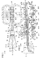
- a metal or plastic strip 2 is pulled off the roll 1 and is guided to the pipe-forming and pipe-filling head 4 via a guide roll 3.
- This head has a molding trough or molding bed 5 and a tube 6 carried therein with a guide section 6a, a molding section 6b and a filling section 6c.
- a filler neck 8 expanded by side channels 9.
- the filler neck 8 is connected to a closed container 11 which contains the insulating material and is integrated in a pressure chamber 12 filled with helium.
- a web 10 is arranged, which covers a certain area to the left and right of a central surface line. The function of this web will be discussed below.
- f üllkopf 4 becomes a tube (2a-d) is formed, wherein the free edges are bent over as a radially outwardly and upwardly projecting flanges 2e Metallblech- or plastic strip.
- Section EF shows shaped bed 5 with a V-shaped strip 2c
- section GH shows a cross section in the area of the filler neck 8, from which the position of the web 10 can also be seen.
- a jaw carousel 16 which consists of two jaw chains which run in an endless loop and which, running between guide rails 17, define a conveying path in which the flanges 2e projecting upwards form one Pipe shaped strip 2 are detected and held frictionally.
- the end 7 of the guiding, shaping and filling tube 6a, b, c extends into the area of the clamping jaws.
- a cover band 18 is unwound from a roller 19 via guide rollers 20 and passed through the tube forming and tube filling head 4 into the preformed tube 2c, d with flange 2e.
- the cover band 18 is placed so that it covers the gap formed by the two flanges 2e upwards. In the area of the filler neck 8, the band is protected and guided by the web 10.
- the cuts JK, LM and NO the location of strip 2 is shown.
- the cable sheath 24 is filled with insulating material 26 via the filler neck and side channels 9 (see section GH and FIG. 2).
- the insulating material now passes through the end 7 of the filling tube 6c into the fully formed cable tube 24 with the flanges 2e (see section LM).
- This process can be adjusted in a metered manner via the vacuum previously existing in the tube 24 on the one hand and the pressure 12 in the insulating material container 11 on the other hand, with evacuation being carried out continuously.
- the cover band 18 is automatically pressed against the slot of the pipe curvature by the flange 2e ; seals this and thus prevents possibly serious contamination from the insulating material 26. Prevention of contamination is particularly important with regard to the subsequent welding of the cable duct jacket.
- the introduction of the insulating material through the filling tube 6c into the cable tube 24 can be supported by an inclined position and a suitable vibration of the guide, molding and filling tube 6a, b, c and thus also the cable tube 24.
- the guide, form and fill tube 6a, b, c can also be in several parts, i. H. consist of several nested pipe sections that can be pulled apart telescopically.
- the fastening plate 14 is arranged vertically adjustable relative to the latter. Analogously, the guide pulley rollers 22 of the cable cores 21 so that they lead centered.
- the masking tape 18 is additionally passed over guide rollers. In this way, all possible combinations are maximally guaranteed and different cable diameters and seamless transitions 58 from one cable diameter to the other can be produced in rapid succession, the density of the insulating material 26 being able to be set the same or different.
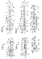
- the cable 25 with the flange 2e at the end 28 of the abutment 15a arrives in a guide groove 29 which, with its jaws, holds the cable all around and firmly closed towards the flange 2e.
- a saw blade 30 arranged horizontally above the guide trough cuts off the upstanding flanges 2e, which are wound up via the rollers 31 and 32.
- the now free edges of the tube are welded at 33.
- These stations are shown schematically in Figures 3 and 4, as well as the sections T-U, V-W and X-Y.
- the finished tubular jacket cable 35 leaves the guide trough 29 and is wound up. Instead of the guide trough 29, it is of course also possible to use a further appropriately shaped clamping carousel.
- FIGS. 5 and 6 A further embodiment of the method or a suitable device is shown in FIGS. 5 and 6 with the associated cuts c-d, e-f, g-h, i-k, and I-m.
- the cable 25 with the flange 2e at the end 28 of the abutment also comes into a guide groove 29, as was explained above.
- a wedge 36 then folds the flanges 2e apart and a subsequent rolling wheel 37 presses the flanges completely flat into a plane tangential to the tubular cable. Then this passes through a welding station, the fold edges being welded at 33 and the flange parts 2e thus being connected hermetically sealed to the cable tube jacket.
- the finished tubular jacket cable 38 with the flange 2e leaves the guide trough.
- the flange 2e which greatly facilitates later installation, can still be punched out (shown at 39), making the cable more flexible.
- An annealing process for relaxation is carried out in a downstream station 40, followed by cleaning and
- FIGS. 7 and 8 show a further variant of an apparatus for carrying out the method according to the invention.
- the cable cores 21 run from the pressure vessel 23 via guide pulley rollers 22 into the guide, form and fill tube 6a, b, c, or are drawn into the tube. This passes through, as already described above, the tube forming and tube filling head 4.
- the molding trough or molding bed 5 is not designed as an outer contour, but rather as a channel in which the metal strip unwound from the roll 1 is guided and gradually into a circular shape brought.
- the filler neck 8 opens the insulating material which is fed by the container 11, which in turn is in communication with the pressure chamber 12.
- the insulating material is fed into the interior of the filling tube 6c with the aid of the pressure differences between the pressure chambers 12 and 23 and the vacuum which surrounds the rest of the device and surrounds the cable wires 21 evenly from all sides.
- This station is shown in the section G-H, from which it can be clearly seen how the strip 2d / 24, which is preformed almost to a full circle, surrounds the section 6b of the filling pipe 6c.
- the casing tube is further bent together until the free edges are directly opposite.
- This phase also takes place in the area of the end 7 of the filling tube 6 (see section J-K).
- the free edges are welded at 33 to form a weld seam 34 (see section J-K).
- the end 7 of the filler tube 6 is flattened such that the change in diameter when leaving the filler tube has no adverse effect on the packing density of the insulating material.
- the packing density need not be as high as is required, for example, in the manufacture of tubes with embedded strain gauges, e.g. B. with pure sheathed cables, thermocouples, resistance thermometers, etc.
- transducers such as strain gauges, resistance thermometers, thermocouples and the like
- Combinations of these in one and the same cable jacket tube are also possible.
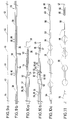
- FIG. 11 shows, for example, a conically widening cable with a totally integrated sensor, the production of which is also possible with the new method.
- an expansion wire 43 is provided with gold-plated areas 44 at predetermined intervals.
- Two equal lengths of wire of the prepared expansion wire are processed to a tubular jacket cable 38 using the manufacturing method described above (FIG. 9b).
- the cable 38 is now cut open at 45 (FIG. 9b) and thus results in the X measuring strips (10a).
- the cable jacket 38 is removed over a certain length (corresponding to the distance between the reference numerals 45 and 46 in FIG. 9b), as a result of which the gold-plated strain gauge wires 44 become visible.
- the insulating material 26 is blown out by means of fine-grained sandblasting, as indicated by arrows.
- the strain gauge 49 thus produced is now connected in a known manner to a cable 35 or 39 in a 3-wire circuit by means of a connecting sleeve 51, the wire ends 21 and 44 are welded together at 59.
- the sleeve 51 is welded on the one hand to the cable 35/39 at 53 and on the other hand to the tube 39/49 of the strain gauge (see Fig. 10b). This creates a strain gauge with an integrated cable, the actual size and appearance of which is shown in FIG. 10c.
- strain gauge 11 shows a strain gauge with a totally integrated cable and a conical transition 58 from the cable 39 to the strain gauge 55/56.
- the strain gauge has integrated fastening flanges 55. The use of the method according to the invention allows the manufacture of such an integrated cable with a transducer in one and the same manufacturing process.
Landscapes
- Physics & Mathematics (AREA)
- General Physics & Mathematics (AREA)
- Engineering & Computer Science (AREA)
- Manufacturing & Machinery (AREA)
- Manufacturing Of Electric Cables (AREA)
Claims (4)
Applications Claiming Priority (2)
| Application Number | Priority Date | Filing Date | Title |
|---|---|---|---|
| DE3109101A DE3109101C2 (de) | 1981-03-10 | 1981-03-10 | Verfahren zur Herstellung von elektrischen Kabeln |
| DE3109101 | 1981-03-10 |
Publications (3)
| Publication Number | Publication Date |
|---|---|
| EP0059971A2 EP0059971A2 (fr) | 1982-09-15 |
| EP0059971A3 EP0059971A3 (en) | 1983-01-19 |
| EP0059971B1 true EP0059971B1 (fr) | 1985-08-28 |
Family
ID=6126829
Family Applications (1)
| Application Number | Title | Priority Date | Filing Date |
|---|---|---|---|
| EP82101838A Expired EP0059971B1 (fr) | 1981-03-10 | 1982-03-08 | Méthode de fabrication de câbles gainés ainsi que dispositif pour l'exécution de la méthode |
Country Status (4)
| Country | Link |
|---|---|
| US (1) | US4437914A (fr) |
| EP (1) | EP0059971B1 (fr) |
| JP (1) | JPS57210518A (fr) |
| DE (1) | DE3109101C2 (fr) |
Families Citing this family (10)
| Publication number | Priority date | Publication date | Assignee | Title |
|---|---|---|---|---|
| DE69005478T2 (de) * | 1989-02-24 | 1994-05-19 | Bicc Plc | Herstellung von mineralisolierten Kabeln. |
| GB9008258D0 (en) * | 1990-04-11 | 1990-06-13 | Bicc Plc | Mineral insulated cable manufacture |
| US5121872A (en) * | 1991-08-30 | 1992-06-16 | Hydrolex, Inc. | Method and apparatus for installing electrical logging cable inside coiled tubing |
| US5479690A (en) * | 1993-12-01 | 1996-01-02 | Hoskins Manufacturing Company | Tube making mechanism having a fill tube for depositing a ceramic powder into the tube as it is being made |
| WO1995018777A1 (fr) * | 1994-01-05 | 1995-07-13 | Roth-Technik Gmbh & Co. Forschung Für Automobil- Und Umwelttechnik | Liaison electriquement conductrice |
| JP2003001323A (ja) * | 2001-06-13 | 2003-01-07 | Mitsubishi Shindoh Co Ltd | 電縫管のスクイズロールユニット装置 |
| NO20101268A1 (no) * | 2010-09-10 | 2012-03-12 | Inst Energiteknik | Kabelstrekkspenningssensor |
| DE102016111738A1 (de) * | 2016-06-27 | 2017-12-28 | Heraeus Sensor Technology Gmbh | Kabel zum Kontaktieren eines Sensors, Temperaturmessvorrichtung, Verfahren zum Verbinden eines Kabels mit einer Temperaturmessvorrichtung und Verwendung einer Legierung zur Herstellung eines Kabels |
| CN113450975B (zh) * | 2021-06-16 | 2022-09-27 | 安徽正豪电缆有限公司 | 一种电缆耐磨防腐护套及其包覆装置 |
| CN114360811B (zh) * | 2021-11-23 | 2024-03-08 | 浙江元通线缆制造有限公司 | 一种连续生产刚性矿物质电缆的生产工艺 |
Family Cites Families (9)
| Publication number | Priority date | Publication date | Assignee | Title |
|---|---|---|---|---|
| FR840026A (fr) * | 1937-12-18 | 1939-04-18 | Procédé et dispositif pour la fabrication de câbles ou de conducteurs blindés à isolant minéral incombustible | |
| DE738591C (de) * | 1938-12-16 | 1943-08-21 | Karl Fischer | Verfahren und Vorrichtung zur Herstellung elektrischer Rohrheizkoerper |
| FR848495A (fr) * | 1939-01-05 | 1939-10-31 | Geoffroy Delore | Procédé et dispositif pour la fabrication des câbles à isolant comprimé |
| US2253069A (en) * | 1939-05-20 | 1941-08-19 | Western Electric Co | Core covering apparatus |
| GB687088A (en) * | 1950-11-14 | 1953-02-04 | Glover & Co Ltd W T | Improvements in the manufacture of insulated electric conductors |
| US3575748A (en) | 1968-05-28 | 1971-04-20 | Gen Cable Corp | Method of making electrical cable |
| US3530019A (en) * | 1968-05-28 | 1970-09-22 | Gen Cable Corp | Apparatus and method for making laminated cable sheath |
| US4093480A (en) | 1974-10-11 | 1978-06-06 | Amp Incorporated | Method for making electrical connectors |
| GB1554859A (en) * | 1975-11-06 | 1979-10-31 | Bicc Ltd | Manufacture of mineral insulated electric cables |
-
1981
- 1981-03-10 DE DE3109101A patent/DE3109101C2/de not_active Expired
-
1982
- 1982-03-08 EP EP82101838A patent/EP0059971B1/fr not_active Expired
- 1982-03-08 US US06/355,455 patent/US4437914A/en not_active Expired - Fee Related
- 1982-03-10 JP JP57037891A patent/JPS57210518A/ja active Pending
Also Published As
| Publication number | Publication date |
|---|---|
| US4437914A (en) | 1984-03-20 |
| DE3109101C2 (de) | 1984-02-23 |
| EP0059971A3 (en) | 1983-01-19 |
| DE3109101A1 (de) | 1982-09-23 |
| EP0059971A2 (fr) | 1982-09-15 |
| JPS57210518A (en) | 1982-12-24 |
Similar Documents
| Publication | Publication Date | Title |
|---|---|---|
| DE4019899C1 (fr) | ||
| DE2746929C2 (de) | Vorrichtung zum Anformen eines gewellten metallischen Schirms mit unverbundener Nahtlinie an einen Kabelkern | |
| DE3114185C2 (de) | Verfahren zur Herstellung einer Umhüllung | |
| EP0059971B1 (fr) | Méthode de fabrication de câbles gainés ainsi que dispositif pour l'exécution de la méthode | |
| DE1932050C3 (de) | Verfahren zum Herstellen eines Streifens isolierter elektrischer AnschluBteile | |
| DE3004357C2 (fr) | ||
| DE2360481C3 (de) | Einseitig verschlossener Hohlstab aus geraffter Schlauchhülle mit im Stabhohlraum liegendem, aus entfältelter Schlauchhülle gebildetem Endverschluß sowie Verfahren zur Herstellung des Verschlusses | |
| DE1960932A1 (de) | Verfahren zur Herstellung waerme- und schallisolierter Leitungsrohre | |
| DE3004387C2 (fr) | ||
| AT407545B (de) | Spannbündel und verfahren sowie vorrichtung zur herstellung desselben | |
| DE1239380B (de) | Verfahren zum Herstellen eines Hochfrequenz-Seekabels | |
| DE69200961T2 (de) | Koaxialkabel. | |
| DE4006094A1 (de) | Hochtemperatursupraleiter aus einem gewellten metallrohr | |
| EP2243567B1 (fr) | Dispositif de fabrication de tuyaux ondulés transversalement par rapport à leur direction longitudinale | |
| DE3204887C2 (fr) | ||
| EP0210411B1 (fr) | Méthode de fabrication d'une gaine métallique pour un câble électrique, avec un contour externe angulaire et interne arrondi | |
| DE1415815B2 (de) | Verfahren zur Herstellung von Abstandshaltern für luftraumisolierte Koaxialkabel | |
| CH368840A (de) | Verfahren und Vorrichtung zum Umhüllen eines Kabels mit einem Metallmantel | |
| DE738591C (de) | Verfahren und Vorrichtung zur Herstellung elektrischer Rohrheizkoerper | |
| DE2829517C2 (de) | Gefüllter Schweißdraht und Verfahren zu seiner Herstellung | |
| DE3034427A1 (de) | Verfahren zur herstellung mineralisch isolierter elektrokabel | |
| DE738627C (de) | Verfahren zur Herstellung von elektrischen Rohrheizkoerpern | |
| DE2001691A1 (de) | Verfahren zur Herstellung von mit laengsliegenden Draehten,Staeben oder fadenaehnlichen Koerpern durchzogenen Rohrleitungen,insbesondere von Waermelanzen | |
| DE1907107C3 (de) | Verfahren zur Herstellung von kupferplattierten Aluminiumdrähten | |
| DE2112462C3 (de) | Verfahren und Vorrichtung zur Herstellung eines aus mehreren Drähten bestehenden Seils o.dgl |
Legal Events
| Date | Code | Title | Description |
|---|---|---|---|
| PUAI | Public reference made under article 153(3) epc to a published international application that has entered the european phase |
Free format text: ORIGINAL CODE: 0009012 |
|
| AK | Designated contracting states |
Designated state(s): BE CH FR GB IT LU NL SE |
|
| PUAL | Search report despatched |
Free format text: ORIGINAL CODE: 0009013 |
|
| AK | Designated contracting states |
Designated state(s): BE CH FR GB IT LI LU NL SE |
|
| 17P | Request for examination filed |
Effective date: 19830630 |
|
| ITF | It: translation for a ep patent filed | ||
| GRAA | (expected) grant |
Free format text: ORIGINAL CODE: 0009210 |
|
| AK | Designated contracting states |
Designated state(s): BE CH FR GB IT LI LU NL SE |
|
| PG25 | Lapsed in a contracting state [announced via postgrant information from national office to epo] |
Ref country code: NL Effective date: 19850828 Ref country code: BE Effective date: 19850828 |
|
| PG25 | Lapsed in a contracting state [announced via postgrant information from national office to epo] |
Ref country code: SE Effective date: 19850830 |
|
| ET | Fr: translation filed | ||
| NLV1 | Nl: lapsed or annulled due to failure to fulfill the requirements of art. 29p and 29m of the patents act | ||
| PG25 | Lapsed in a contracting state [announced via postgrant information from national office to epo] |
Ref country code: LU Free format text: LAPSE BECAUSE OF NON-PAYMENT OF DUE FEES Effective date: 19860331 |
|
| PLBE | No opposition filed within time limit |
Free format text: ORIGINAL CODE: 0009261 |
|
| STAA | Information on the status of an ep patent application or granted ep patent |
Free format text: STATUS: NO OPPOSITION FILED WITHIN TIME LIMIT |
|
| 26N | No opposition filed | ||
| ITTA | It: last paid annual fee | ||
| PGFP | Annual fee paid to national office [announced via postgrant information from national office to epo] |
Ref country code: GB Payment date: 19920826 Year of fee payment: 11 |
|
| PGFP | Annual fee paid to national office [announced via postgrant information from national office to epo] |
Ref country code: FR Payment date: 19920916 Year of fee payment: 11 |
|
| PGFP | Annual fee paid to national office [announced via postgrant information from national office to epo] |
Ref country code: CH Payment date: 19920918 Year of fee payment: 11 |
|
| PG25 | Lapsed in a contracting state [announced via postgrant information from national office to epo] |
Ref country code: GB Effective date: 19930308 |
|
| PG25 | Lapsed in a contracting state [announced via postgrant information from national office to epo] |
Ref country code: CH Effective date: 19930331 Ref country code: LI Effective date: 19930331 |
|
| GBPC | Gb: european patent ceased through non-payment of renewal fee |
Effective date: 19930308 |
|
| PG25 | Lapsed in a contracting state [announced via postgrant information from national office to epo] |
Ref country code: FR Effective date: 19931130 |
|
| REG | Reference to a national code |
Ref country code: CH Ref legal event code: PL |
|
| REG | Reference to a national code |
Ref country code: FR Ref legal event code: ST |