EP0060563A1 - Dispositif de commande d'interpolation pour robot articulé industriel - Google Patents
Dispositif de commande d'interpolation pour robot articulé industriel Download PDFInfo
- Publication number
- EP0060563A1 EP0060563A1 EP82102151A EP82102151A EP0060563A1 EP 0060563 A1 EP0060563 A1 EP 0060563A1 EP 82102151 A EP82102151 A EP 82102151A EP 82102151 A EP82102151 A EP 82102151A EP 0060563 A1 EP0060563 A1 EP 0060563A1
- Authority
- EP
- European Patent Office
- Prior art keywords
- reference clock
- interpolation
- register
- wrist
- linear interpolation
- Prior art date
- Legal status (The legal status is an assumption and is not a legal conclusion. Google has not performed a legal analysis and makes no representation as to the accuracy of the status listed.)
- Granted
Links
Images

Classifications
-
- G—PHYSICS
- G05—CONTROLLING; REGULATING
- G05B—CONTROL OR REGULATING SYSTEMS IN GENERAL; FUNCTIONAL ELEMENTS OF SUCH SYSTEMS; MONITORING OR TESTING ARRANGEMENTS FOR SUCH SYSTEMS OR ELEMENTS
- G05B19/00—Program-control systems
- G05B19/02—Program-control systems electric
- G05B19/18—Numerical control [NC], i.e. automatically operating machines, in particular machine tools, e.g. in a manufacturing environment, so as to execute positioning, movement or co-ordinated operations by means of program data in numerical form
- G05B19/41—Numerical control [NC], i.e. automatically operating machines, in particular machine tools, e.g. in a manufacturing environment, so as to execute positioning, movement or co-ordinated operations by means of program data in numerical form characterised by interpolation, e.g. the computation of intermediate points between programmed end points to define the path to be followed and the rate of travel along that path
-
- G—PHYSICS
- G05—CONTROLLING; REGULATING
- G05B—CONTROL OR REGULATING SYSTEMS IN GENERAL; FUNCTIONAL ELEMENTS OF SUCH SYSTEMS; MONITORING OR TESTING ARRANGEMENTS FOR SUCH SYSTEMS OR ELEMENTS
- G05B2219/00—Program-control systems
- G05B2219/30—Nc systems
- G05B2219/34—Director, elements to supervisory
- G05B2219/34037—Brm followed by postprocessor to smooth curve
-
- G—PHYSICS
- G05—CONTROLLING; REGULATING
- G05B—CONTROL OR REGULATING SYSTEMS IN GENERAL; FUNCTIONAL ELEMENTS OF SUCH SYSTEMS; MONITORING OR TESTING ARRANGEMENTS FOR SUCH SYSTEMS OR ELEMENTS
- G05B2219/00—Program-control systems
- G05B2219/30—Nc systems
- G05B2219/34—Director, elements to supervisory
- G05B2219/34167—Coarse fine, macro microinterpolation, preprocessor
-
- G—PHYSICS
- G05—CONTROLLING; REGULATING
- G05B—CONTROL OR REGULATING SYSTEMS IN GENERAL; FUNCTIONAL ELEMENTS OF SUCH SYSTEMS; MONITORING OR TESTING ARRANGEMENTS FOR SUCH SYSTEMS OR ELEMENTS
- G05B2219/00—Program-control systems
- G05B2219/30—Nc systems
- G05B2219/34—Director, elements to supervisory
- G05B2219/34179—Variable interpolation speed or resolution
-
- G—PHYSICS
- G05—CONTROLLING; REGULATING
- G05B—CONTROL OR REGULATING SYSTEMS IN GENERAL; FUNCTIONAL ELEMENTS OF SUCH SYSTEMS; MONITORING OR TESTING ARRANGEMENTS FOR SUCH SYSTEMS OR ELEMENTS
- G05B2219/00—Program-control systems
- G05B2219/30—Nc systems
- G05B2219/43—Speed, acceleration, deceleration control ADC
- G05B2219/43006—Acceleration, deceleration control
Definitions
- This invention relates to a linear interpolation control device for an industrial articulated robot.
- interpolation outputs in the orthogonal coordinate system may be applied directly to drive axes X, Y and Z.
- an articulated robot needs intricate. coordinate transformation between the articulation drive axes and the orthogonal coordinates in addition to the interpolation in the orthogonal coordinate system.
- an expensive device such as a minicomputer.
- a minicomputer-operated robot has not been practically used yet, because it is not economical as an industrial articulated robot.
- an interpolation in which 1 pulse increment is applied to each drive axis every reference clock is not always necessary in a linear interpolation between two points taught, because, in the case where the distance between two points taught is short, it is moved straightly with practically high accuracy if uniform pulse distribution (simultaneous start and simultaneous stop method) is effected for the articulation drive axes so that the axes are moved at speeds specified.
- an interpolation control in which interpolation errors can be neglected, can be achieved.
- the distance between two points taught is divided into segments which are defined by a tangential speed, a reference clock and the distance between the two points.
- the increment. pulse numbers of the articulation drive axes, which correspond to each of the segments, are subjected to interpolation calculation, and BRMs (binary rated multipliers) are used to subject the increment pulse numbers to uniform pulse distribution in the sense of time.
- this invention is advantageous in that it can be realized merely by adding some hardware such as BRMs to an inexpensive arithmetic unit.because, in this invention, segment interpolation is employed and no trouble is caused even if it takes a relatively long period of time to achieve the interpolation calculation including the coordinate transformation.
- the posture of the gun is determined according to the contents of work and the kinds of work. For instance in the case of a welding robot, the posture of the gun, which is defined by a torch angle, an advancing angle, etc. must be maintain constant to the extent that the posture causes no trouble in the welding operation.
- An object of this invention is to provide a control device for an articulated robot in which the amounts of segment for every reference clock are switched according to whether or not the speed of the wrist axes exceeds the maximum number of revolutions per minute of the drive motor so that in both cases the position of the wrist is uniformly changed between two points for linear interpolation, interpolation calculation is carried out with high accuracy with an inexpensive simple arithmetic unit and a BRM pulse distribution circuit with two-stage buffer means, and no stop occurs at a turning point between linear interpolations; i.e., linear interpolation is carried out by smoothly connecting straight lines.
- a control device for an industrial articulated robot according to .
- a teaching playback system in which, when linear-interpolation between two points specified is carried out, a distance between the two points is divided into segments which are defined by a tangential speed, a reference clock and the distance between the two points, and increment pulse numbers of articulation drive axes, which correspond to each of the segments, are subjected to interpolation calculation, so that the increment pulses numbers are pulse-distributed uniformly in a sense of time.
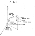
- FIG. 1 shows a model of a multi-articulated robot.
- the rotary axis, the lower arm axis L and the upper arm axis l are controlled by rotation angles ⁇ , 8 and ⁇ , respectively; and the wrist bending axis and the turning axis are controlled by rotation angles y and ⁇ , respectively.
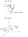
- FIG. 2 shows the wrist of the robot and a gun secured thereto.
- the point P which is spaced a distance A from the center Q of rotation of the wrist bending axis and a distance B from the center of rotation of the turning axis is a control point which should be subjected to linear interpolation.
- the position of the point P can be expressed in the orthogonal coordinate system by using the articulation drive angles ⁇ , 8, ⁇ , ⁇ and T , according to the following expressions:
- N 1 The number of times (N 1 ) of segment interpolation . for every reference clock is:
- This value is the amount of movement for every reference clock, i.e., the speed.
- N 1 >N 2 and N 1 >N 3 the amount of segment is as indicated by the expression (4); and when N 2 >N 1 and N 2 >N 3 , When N 3 >N 1 and N 3 > N 2 , N 3 is substituted for N 2 in the expression (6).
- the values ⁇ x, ⁇ y and ⁇ z which are calculated according to the expression (4) or (6) are accumulated as present values. Reverse transformation is effected by using the present values x, y, z, y and ⁇ , to obtain ⁇ , 8 and ⁇ .
- the differences ⁇ , ⁇ , ⁇ , ⁇ ⁇ between these values ( ⁇ , ⁇ , ⁇ , y, ⁇ ) and those at the previous reference clock are outputted,as command pulses,to the axis drive position servo-mechanisms through the BRM, to subject the control point P to linear interpolation.
- FIG. 3 is an explanatory diagram for a description of the case where the linear interpolation between the start point P 1 and the end point P 2 is carried out while linear acceleration and deceleration are effected.
- the number of times of segment interpolation N 0 in the acceleration and deceleration time T 0 is:
- An advance distance L(N) in the time T 0 is:
- N 4 The number (N 4 ) of times of segment interpolation for the acceleration and deceleration part is:
- N 5 The number (N 5 ) of times of segment interpolation for the steady speed part is:
- N 1 the total number (N 1 ) of times of segment interpolation
- N 1 thus obtained is compared with N 2 or N 3 .
- N 1 is employed as the total number of times of segment interpolation, as it is.
- the axes components of the advance distance for the acceleration part are: and the axes components of the advance distance for the steady speed part is:
- Each advance distance can be obtained by dividing the expression (12) by N 5 .
- values obtained by adding the expression (11) to the coordinates of the start point are employed as the present values.
- values obtained by adding the preceding values to values obtained by dividing the expression (12) by N5 are employed as the present values.
- ⁇ , 6 and ⁇ are obtained from the present values of x, y, z and ⁇ and ⁇ similarly as in the case where no acceleration and deceleration is effected, and the difference ⁇ , ⁇ , ⁇ , ⁇ and. AT between the present values at the present reference clock and.those at the previous reference clock are applied, as command pulses, to the axes servos through the aforementioned BRM.
- FIG. 4 is a block diagram showing the connection of a linear interpolation control unit composed of an arithmetic unit and a BRM with two stages of buffers, and main CPU (central processing unit) for controlling them.
- the main CPU 409 reads out of a memory (not shown). data of each axis pulse number from the original position of the articulation drive axes, tangential speed and presence or absence of acceleration or deceleration at the start point and the end point of linear interpolation, to set the data in a register "1" (406), a register "2" (407) and a register "3" (408), and outputs a linear interpolation start macrocommand 4009.
- the arithmetic unit 400 is composed of a sequence controller 401, a microprogram memory 402, a pipe line register 403, a multiplexer 404, a RALU (register and arithmetic logical unit) 405, the register "1" (406), the register "2" (407) and the register "3" (408).
- the sequence controller 401 is an address controller for controlling the execution sequence of microinstruc- tions stored in the microprogram memory 402. It carries' out various addressing and stack control according to a control instructions 4002 from the pipe line register 403.
- the sequence controller 401 deals with increment of an address being executed, selection of an address specified by a macrocommand 4009, selection of an address specified by a reference clock address generator 415, selection of a jump address given by the pipe line register 403 in the case of conditional jump according to a test condition 4003 including a status 4008 of the RALU, selection of a jump address given by the pipe line register 403 in the case of non-conditional jump, and stack control at the time of microsubroutine call.
- the macrocommand 4009, and outputs from the reference clock address generator 415 and the pipe line register 403 are employed as input data for addressing.
- the sequence controller 401 selects one of these data according to a microprogram, i.e., control instructions 4002 from the pipe line register 403.
- a linear interpolation start command is provided as the macrocommand 4009.
- the command is provided to indicate the entry address (hereinafter represented merely by a symbol N#, when applicable) of a linear interpolation service microprogram in view.of hardware.
- the output of the reference clock address generator 415 is provided to indicate the entry address (hereinafter represented merely by a symbol M#, when applicable) of a service microprogram for obtaining the numbers of the increment pulses ⁇ , ⁇ , ⁇ , ⁇ and ⁇ of each articulation from the aforementioned data ⁇ x, ⁇ y, ⁇ z, Ay and ⁇ .
- M# is included in a series of microprograms for obtaining the numbers of the increment pulses ⁇ , ⁇ , ⁇ , ⁇ yand ⁇ , beginning with N#.
- the arithmetic unit 400 waits for a reference clock 4006 in a wait routine.
- the arithmetic unit 400 starts an arithmetic operation for obtaining ⁇ , ⁇ , ⁇ , ⁇ and AT beginning with M#, and waits for the next reference clock 4006. The unit 400 repeatedly carries out this operation until an block end occurs.
- addressing is effected by a jump address, subroutine call address and current address increment provided by the pipe line register 403.
- the microprogram memory 402 is the center of the arithmetic unit 400. All of the arithmetic operations are carried out according to instructions from the microprogram memory 402.
- the pipe line register 403 is a buffer register for the microprogram memory 402.
- the register 403 outputs micro instructions to be executed at the present time to the RALU 405, outputs control instructions 4002 for determining the next microaddress to the sequence controller 401 and the multiplexer 404, and outputs the jump address, subroutine call address and current address increment to the sequence controller 401.
- the pipe line register 403 applies a command request 4007 to the main CPU,
- the pipe line register 403 form two signal paths.
- the operations in the signal paths are carried out in a parallel mode, to reduce a micro cycle time to increase the arithmetic operation speed.
- One of the two signal paths is a control path consisting of the pipe line register 403, the sequence controller 401 and the microprogram memory 402 which are connected in the stated order, and the.other is an arithmetic path consisting of the pipe line register 403 and the RALU.
- the pipe line register. 403 is provided in order to operate the two paths in a parallel mode during the same clock cycle.
- the multiplexer 404 applies the RALU status 4008 and test conditions 4003 such as external conditions to the sequence controller 401 in response to the control instructions from the pipe line register 403, thereby to effect the conditional jump.
- the RALU 405 is made up of a logic and arithmetic calculation unit and programmable registers, to carry out calculation instructions specified by the microprogram.
- the calculation results, or the increment pulse numbers of the articulation drive axes for every reference clock are stored in the predetermined registers in the RALU 405.
- the register "1" (406) and the register “2" (407) store the numbers of pulses from.the original positions of the articulation drive axes at the start and end points of a linear interpolation.
- the register "3" (408) stores tangential speed of linear interpolation, acceleration and deceleration time, and presence or absence of acceleration or deceleration.
- Buffers "1" (411a through 411e) are registers which store increment pulse numbers which are to be outputted with the next reference clock for each articulation drive axis
- buffers "2" (412a through 412e) are registers which store increment pulse numbers which are being outputted at the present time.
- BRMs 413a through 413e uniformly distribute, as pulses synchronous with a clock ⁇ 4005, the pulse numbers stored'in the buffers "2" within the reference clock period, and output completion signals 4004a - 4004e for buffer transferring every reference clock 4006.
- the buffers "1", the buffers "2" and the BRMs form a two-stage buffer pulse distributing unit.
- a frequency division and differentiation circuit 414 form the reference clock 4006, from the clock ⁇ 4005, which was frequency-divided by the number of bits of the BRMs 413a through 413e, to synchronize the BRM output completion signals 4004a - 4004e with the reference clock 4006.
- reference numeral 415 designates an address generator to generate M# from-the reference clock 4006.
- the arithmetic unit 400 first executes the wait routine, to cause the pipe line register 403 to apply the command request 4007 to the main CPU 409.
- the sequence controller 401 carries out address control to perform the wait routine while receiving the control instruction 4002 for N# selection from the pipe line register 403, upon reception of the macrocommand 4009.
- the wait routine includes an instruction 4008 for resetting the frequency division and differentiation circuit 414, no reference clock 4006 is produced thereby.
- the main CPU 409 sets data 4010 of start point, end point, tangential speed, acceleration and deceleration time and presence or absence of acceleration or deceleration in the register "1" 406, the register "2" 407 and the register "3" 408.
- the circuit 414 starts counting the clock ⁇ (4005).
- sequence controller 401 operates to carry out the addressing necessary for arithmetic operation, until the generation of the output from the reference clock address generator 415.
- the arithmetic unit 400 calculates P 1 (x 1 , y 1 , z l ) and P 2 (x 2 , y 2 , z 2 ) according to the expression (1) with the pulses numbers of each articulation drive axis at the start and end points, and obtains the distance D.from the expression (2) and the values N 2 and N 3 from the expression (5).
- the arithmetic unit 400 further obtain the number (N l ) of times of segment interpolation for every clock by inserting the tangential speed V 0 stored in the register "3" in the expression (3).
- N 1 , N 2 and N 3 are subjected to comparison, so that segments (amounts of increment) ⁇ x, ⁇ y, ⁇ z, ⁇ and AT per reference clock 4006 are obtained from the expression (4) or (6).
- the microprogram advances to M#, the values , ⁇ and ⁇ are obtained through the reverse conversion of the expression (1) by using the present values which are obtained by adding ⁇ x, ⁇ y, Az, ⁇ and ⁇ to x 1 , y 1 , z 1 , ⁇ 1 and ⁇ 1 of the start point.
- the differences ⁇ , ⁇ , ⁇ , ⁇ and ⁇ between the values ⁇ , ⁇ , ⁇ , y and ⁇ and the values ⁇ 1 , ⁇ 1 , ⁇ 1 , ⁇ 1 and ⁇ 1 of the start poi.nt are set in the predetermined registers in the RALU 405, and a wait routine is performed.
- the wait routine unlike a wait routine for waiting for N#, waits .for the next reference clock 4006, i.e., M#, and the frequency division rise differentiation circuit 414 is not reset.
- the clock ⁇ 4005 and the number of bits of the BRMs 413a through 413e are so set that the reference clock (4006) period is longer than the time interval which elapses until the above-described calculations are achieved. Therefore, even if the calculation time is sufficiently long, there is no trouble.
- the arithmetic unit 400 performs the wait routine for waiting for M#, when the reference clock 4006 is produced, simultaneously the BRMs 413a through 413e output the output completion signals,. so that ⁇ , ⁇ , ⁇ , Ay and ⁇ from the predetermined registers in the RALU 405 are loaded in the five buffers "1" (411a through 411e) , respectively, and the contents of the buffers "1" (411a through 411e) are loaded in the buffers "2" (412a through 412e).
- The- reference clock address generator 415 is operated by the reference clock 4006, the microprogram is executed beginning with M#, so that ⁇ , ⁇ , ⁇ , y and T are obtained through reverse conversion of the expression (1) by using the new present values which are obtained by adding the increments ⁇ x, ⁇ y, ⁇ z, ⁇ and AT of this time to the previous present values x, y, z, y and T, and the differences ⁇ , ⁇ , ⁇ , ⁇ and AT are set in the predetermined registers in the RALU 405 similarly as in the above-described case, and the wait routine for waiting for the next M# is effected.
- linear interpolation is carried out with high accuracy while the wrist is finely controlled by the linear interporation apparatus which is composed of the arithmetic unit and the BRMs with the buffers, and is low in manufacturing cost and simple in construction. Therefore, teaching can be readily achieved when the articulated robot is applied to an object which has a number of linear parts.
- interpolation is effected by . calculating the amounts of increment in position every reference clock which are defined by the distance between two points, the specified tangential speed and the reference clock. Therefore,
Landscapes
- Engineering & Computer Science (AREA)
- Computing Systems (AREA)
- Theoretical Computer Science (AREA)
- Human Computer Interaction (AREA)
- Manufacturing & Machinery (AREA)
- Physics & Mathematics (AREA)
- General Physics & Mathematics (AREA)
- Automation & Control Theory (AREA)
- Numerical Control (AREA)
Applications Claiming Priority (2)
| Application Number | Priority Date | Filing Date | Title |
|---|---|---|---|
| JP38872/81 | 1981-03-18 | ||
| JP56038872A JPS584377A (ja) | 1981-03-18 | 1981-03-18 | 関節形産業用ロボツトの制御装置 |
Publications (2)
| Publication Number | Publication Date |
|---|---|
| EP0060563A1 true EP0060563A1 (fr) | 1982-09-22 |
| EP0060563B1 EP0060563B1 (fr) | 1987-09-30 |
Family
ID=12537297
Family Applications (1)
| Application Number | Title | Priority Date | Filing Date |
|---|---|---|---|
| EP82102151A Expired EP0060563B1 (fr) | 1981-03-18 | 1982-03-17 | Dispositif de commande d'interpolation pour robot articulé industriel |
Country Status (4)
| Country | Link |
|---|---|
| US (1) | US4528632A (fr) |
| EP (1) | EP0060563B1 (fr) |
| JP (1) | JPS584377A (fr) |
| DE (1) | DE3277422D1 (fr) |
Cited By (3)
| Publication number | Priority date | Publication date | Assignee | Title |
|---|---|---|---|---|
| EP0098386A3 (en) * | 1982-06-10 | 1985-05-15 | Cincinnati Milacron Inc. | Manipulator with controlled path motion |
| EP0101955A3 (en) * | 1982-08-04 | 1986-07-02 | Hitachi, Ltd. | Path control method and apparatus |
| CN107234618A (zh) * | 2017-08-08 | 2017-10-10 | 广东工业大学 | 一种二自由度机械手臂控制方法及其装置 |
Families Citing this family (34)
| Publication number | Priority date | Publication date | Assignee | Title |
|---|---|---|---|---|
| US5307447A (en) * | 1982-10-29 | 1994-04-26 | Kabushiki Kaisha Toshiba | Control system of multi-joint arm robot apparatus |
| EP0108549B1 (fr) * | 1982-10-29 | 1988-01-07 | Kabushiki Kaisha Toshiba | Système de contrôle pour bras de robot multi-articulé |
| JPS59218513A (ja) * | 1983-05-26 | 1984-12-08 | Fanuc Ltd | 工業用ロボツトの円弧制御法 |
| JPS6020209A (ja) * | 1983-07-14 | 1985-02-01 | Matsushita Electric Ind Co Ltd | ロボツトの補間制御方法 |
| US4689756A (en) * | 1984-06-29 | 1987-08-25 | Shin Meiwa Industry Co., Ltd. | Robot interpolation control method |
| US4734866A (en) * | 1984-07-05 | 1988-03-29 | Siemens Aktiengesellschaft | Computer controller for an industrial multiaxis robot |
| JPS6154506A (ja) * | 1984-08-24 | 1986-03-18 | Fanuc Ltd | ア−ク開始点探索時のツ−ルの探索姿勢制御方式 |
| JPS6261104A (ja) * | 1985-09-11 | 1987-03-17 | Fanuc Ltd | 水平関節型ロボツトの加減速制御方式 |
| US4716350A (en) * | 1986-12-08 | 1987-12-29 | Ford Motor Company | Method to avoid singularity in a robot mechanism |
| US4956789A (en) * | 1987-05-13 | 1990-09-11 | Hitachi, Ltd. | Method and apparatus for driving a servo system while suppressing residual vibration generated during position control |
| US4835710A (en) * | 1987-07-17 | 1989-05-30 | Cincinnati Milacron Inc. | Method of moving and orienting a tool along a curved path |
| JP2707087B2 (ja) * | 1987-09-09 | 1998-01-28 | ファナック株式会社 | ロボット制御装置 |
| JPH01252389A (ja) * | 1988-03-31 | 1989-10-09 | Agency Of Ind Science & Technol | マニピュレータ及びその制御方法 |
| IL86938A (en) * | 1988-06-30 | 1992-02-16 | Nissim Igal Levi | Method and apparatus for contouring data particularly useful in preparing topographic maps |
| JP2512099B2 (ja) * | 1988-08-24 | 1996-07-03 | 松下電器産業株式会社 | ロボットの動作教示方法および制御装置 |
| JPH079606B2 (ja) * | 1988-09-19 | 1995-02-01 | 豊田工機株式会社 | ロボット制御装置 |
| DE58909509D1 (de) * | 1989-02-28 | 1996-01-04 | Siemens Ag | Steuerungsverfahren bei einer numerischen Werkzeugmaschine oder einem Roboter. |
| US5825980A (en) * | 1989-05-26 | 1998-10-20 | Canon Kabushiki Kaisha | Robot hand structure, and method of selecting hand structure |
| EP0477397B2 (fr) * | 1990-09-25 | 1999-09-01 | Dr. Johannes Heidenhain GmbH | Procédé pour déterminer le contour de trajectoire de l'outil pour machines à commande numérique |
| JPH04167006A (ja) * | 1990-10-31 | 1992-06-15 | Komatsu Ltd | ロボットの制御方法 |
| JPH04167005A (ja) * | 1990-10-31 | 1992-06-15 | Komatsu Ltd | ロボットの制御方法 |
| KR930007775B1 (ko) * | 1990-12-28 | 1993-08-19 | 삼성전자 주식회사 | 로보트의 직선보간(補間)방법 |
| DE4123323C2 (de) * | 1991-07-13 | 1994-02-10 | Andreas Ehlerding | Werkzeugträger |
| JP3036143B2 (ja) * | 1991-09-02 | 2000-04-24 | 三菱電機株式会社 | 数値制御装置 |
| WO1993022107A1 (fr) * | 1992-04-23 | 1993-11-11 | Kabushiki Kaisha Komatsu Seisakusho | Procede de commande concernant un robot industrial |
| US6535794B1 (en) | 1993-02-23 | 2003-03-18 | Faro Technologoies Inc. | Method of generating an error map for calibration of a robot or multi-axis machining center |
| US5373221A (en) * | 1993-07-30 | 1994-12-13 | Fanuc Robotics North America, Inc. | Method and system for estimating robot tool center point speed |
| US5495410A (en) * | 1994-08-12 | 1996-02-27 | Minnesota Mining And Manufacturing Company | Lead-through robot programming system |
| WO2004108365A1 (fr) * | 2003-06-02 | 2004-12-16 | Honda Motor Co., Ltd. | Procede de preparation de donnees d'apprentissage pour robot articule |
| US20070142966A1 (en) * | 2005-12-20 | 2007-06-21 | Khalid Mirza | Process for moving a robot |
| TWI375140B (en) * | 2008-10-13 | 2012-10-21 | Ind Tech Res Inst | Accumulative method for estimating a processing velocity limitation and method for controlling acceleration and deceleration before interpolation |
| JP5897259B2 (ja) * | 2011-02-02 | 2016-03-30 | 東芝機械株式会社 | 工作機械およびその制御方法 |
| EP2774729A4 (fr) * | 2011-09-15 | 2016-05-18 | Yaskawa Denki Seisakusho Kk | Système robotique et unité de commande de robot |
| CN104133424B (zh) * | 2014-08-19 | 2017-01-18 | 福州大学 | 一种基于可编程控制器的工业机器人直线插补方法 |
Citations (3)
| Publication number | Priority date | Publication date | Assignee | Title |
|---|---|---|---|---|
| US3727191A (en) * | 1971-03-15 | 1973-04-10 | Giddings & Lewis | Acceleration-deceleration for numerical control |
| FR2384296A1 (fr) * | 1977-03-16 | 1978-10-13 | Ifelec | Dispositif de controle du deplacement par increment rectiligne d'un org |
| FR2460000A1 (fr) * | 1979-06-27 | 1981-01-16 | Adepa | Dispositif de commande de mouvement d'un systeme a plusieurs degres de liberte |
Family Cites Families (13)
| Publication number | Priority date | Publication date | Assignee | Title |
|---|---|---|---|---|
| NL291454A (fr) * | 1959-12-24 | |||
| US3518513A (en) * | 1965-09-03 | 1970-06-30 | Olivetti & Co Spa | Position control device comprising an interpolating unit |
| GB1189959A (en) * | 1965-09-03 | 1970-04-29 | Olivetti & Co Spa | Improvements in Numerical Control Devices |
| US3909600A (en) * | 1972-06-26 | 1975-09-30 | Cincinnati Milacron Inc | Method and apparatus for controlling an automation along a predetermined path |
| US3864557A (en) * | 1973-08-29 | 1975-02-04 | Warner Swasey Co | Interpolator for machine tool control |
| US3920972A (en) * | 1974-07-16 | 1975-11-18 | Cincinnati Milacron Inc | Method and apparatus for programming a computer operated robot arm |
| US4163184A (en) * | 1974-10-04 | 1979-07-31 | The Superior Electric Company | Arcuate movement numerical control method and system |
| JPS5911921B2 (ja) * | 1975-07-17 | 1984-03-19 | 日本電気株式会社 | 数値制御装置 |
| JPS586163B2 (ja) * | 1975-07-18 | 1983-02-03 | 日本放送協会 | 被制御装置の駆動装置 |
| US4031369A (en) * | 1975-08-12 | 1977-06-21 | The Bendix Corporation | Interpolation and control apparatus and method for a numerical control system |
| US4163183A (en) * | 1975-10-28 | 1979-07-31 | Unimation, Inc. | Programmable automatic assembly system |
| JPS6045442B2 (ja) * | 1976-02-25 | 1985-10-09 | 豊田工機株式会社 | 直線補間パルス分配方式 |
| US4338672A (en) * | 1978-04-20 | 1982-07-06 | Unimation, Inc. | Off-line teach assist apparatus and on-line control apparatus |
-
1981
- 1981-03-18 JP JP56038872A patent/JPS584377A/ja active Pending
-
1982
- 1982-03-08 US US06/355,657 patent/US4528632A/en not_active Expired - Fee Related
- 1982-03-17 EP EP82102151A patent/EP0060563B1/fr not_active Expired
- 1982-03-17 DE DE8282102151T patent/DE3277422D1/de not_active Expired
Patent Citations (3)
| Publication number | Priority date | Publication date | Assignee | Title |
|---|---|---|---|---|
| US3727191A (en) * | 1971-03-15 | 1973-04-10 | Giddings & Lewis | Acceleration-deceleration for numerical control |
| FR2384296A1 (fr) * | 1977-03-16 | 1978-10-13 | Ifelec | Dispositif de controle du deplacement par increment rectiligne d'un org |
| FR2460000A1 (fr) * | 1979-06-27 | 1981-01-16 | Adepa | Dispositif de commande de mouvement d'un systeme a plusieurs degres de liberte |
Cited By (3)
| Publication number | Priority date | Publication date | Assignee | Title |
|---|---|---|---|---|
| EP0098386A3 (en) * | 1982-06-10 | 1985-05-15 | Cincinnati Milacron Inc. | Manipulator with controlled path motion |
| EP0101955A3 (en) * | 1982-08-04 | 1986-07-02 | Hitachi, Ltd. | Path control method and apparatus |
| CN107234618A (zh) * | 2017-08-08 | 2017-10-10 | 广东工业大学 | 一种二自由度机械手臂控制方法及其装置 |
Also Published As
| Publication number | Publication date |
|---|---|
| JPS584377A (ja) | 1983-01-11 |
| US4528632A (en) | 1985-07-09 |
| EP0060563B1 (fr) | 1987-09-30 |
| DE3277422D1 (en) | 1987-11-05 |
Similar Documents
| Publication | Publication Date | Title |
|---|---|---|
| EP0060563B1 (fr) | Dispositif de commande d'interpolation pour robot articulé industriel | |
| US4495588A (en) | Robot locus control system | |
| US4868474A (en) | Multiprocessor position/velocity servo control for multiaxis digital robot control system | |
| US4150329A (en) | Method and means in an industrial robot for the generation of a complex movement | |
| US4851748A (en) | Basic digital multi-axis robot control having modular performance expansion capability | |
| US4868472A (en) | Communication interface for multi-microprocessor servo control in a multi-axis robot control system | |
| US4763055A (en) | Digital robot control having high performance servo control system | |
| JPS63141110A (ja) | ロボットのデジタル制御装置 | |
| CN104133424A (zh) | 一种基于可编程控制器的工业机器人直线插补方法 | |
| EP0268491A2 (fr) | Robot multiaxal à commande de mouvement | |
| US4677276A (en) | Method of welding robot control which controls the three basic axes of a robot to provide a repetition of a weaving pattern along a robot locus | |
| CN117555293A (zh) | 一种运动控制器的控制方法、系统、电子设备及存储介质 | |
| WO1989008878A1 (fr) | Procede de commande de l'orientation d'un outil dans un robot | |
| KR0168065B1 (ko) | 수치제어시스템의 모터제어방법 및 그 장치 | |
| US5463297A (en) | Circular tracking method for robot | |
| CN112677150B (zh) | 机械臂的控制方法、装置、电子设备及存储介质 | |
| CN113459103B (zh) | 一种机械手自动运行时的转角轨迹控制方法及装置 | |
| JPH0428471B2 (fr) | ||
| JPH1039916A (ja) | 多関節ロボットの加減速制御方法 | |
| JPH0775357A (ja) | 子局同時起動方法及び装置 | |
| JPH05261546A (ja) | 溶接ロボットの制御方法 | |
| JPS5823186B2 (ja) | ヨウセツヨウロボツトノ セイギヨソウチ | |
| WO1990008993A1 (fr) | Unite de commande numerique pour ligne de transfert | |
| JPS63239511A (ja) | ロボツト・システム | |
| JPH04367373A (ja) | 溶接ロボットの制御方法 |
Legal Events
| Date | Code | Title | Description |
|---|---|---|---|
| PUAI | Public reference made under article 153(3) epc to a published international application that has entered the european phase |
Free format text: ORIGINAL CODE: 0009012 |
|
| AK | Designated contracting states |
Kind code of ref document: A1 Designated state(s): CH DE FR GB SE Designated state(s): CH DE FR GB SE |
|
| 17P | Request for examination filed |
Effective date: 19830222 |
|
| GRAA | (expected) grant |
Free format text: ORIGINAL CODE: 0009210 |
|
| AK | Designated contracting states |
Kind code of ref document: B1 Designated state(s): CH DE FR GB LI SE |
|
| REF | Corresponds to: |
Ref document number: 3277422 Country of ref document: DE Date of ref document: 19871105 |
|
| ET | Fr: translation filed | ||
| PLBE | No opposition filed within time limit |
Free format text: ORIGINAL CODE: 0009261 |
|
| STAA | Information on the status of an ep patent application or granted ep patent |
Free format text: STATUS: NO OPPOSITION FILED WITHIN TIME LIMIT |
|
| 26N | No opposition filed | ||
| PGFP | Annual fee paid to national office [announced via postgrant information from national office to epo] |
Ref country code: FR Payment date: 19890308 Year of fee payment: 8 |
|
| PGFP | Annual fee paid to national office [announced via postgrant information from national office to epo] |
Ref country code: SE Payment date: 19890313 Year of fee payment: 8 |
|
| PGFP | Annual fee paid to national office [announced via postgrant information from national office to epo] |
Ref country code: CH Payment date: 19890328 Year of fee payment: 8 |
|
| PGFP | Annual fee paid to national office [announced via postgrant information from national office to epo] |
Ref country code: GB Payment date: 19890331 Year of fee payment: 8 |
|
| PGFP | Annual fee paid to national office [announced via postgrant information from national office to epo] |
Ref country code: DE Payment date: 19890428 Year of fee payment: 8 |
|
| PG25 | Lapsed in a contracting state [announced via postgrant information from national office to epo] |
Ref country code: GB Effective date: 19900317 |
|
| PG25 | Lapsed in a contracting state [announced via postgrant information from national office to epo] |
Ref country code: SE Effective date: 19900318 |
|
| PG25 | Lapsed in a contracting state [announced via postgrant information from national office to epo] |
Ref country code: LI Effective date: 19900331 Ref country code: CH Effective date: 19900331 |
|
| GBPC | Gb: european patent ceased through non-payment of renewal fee | ||
| PG25 | Lapsed in a contracting state [announced via postgrant information from national office to epo] |
Ref country code: FR Effective date: 19901130 |
|
| REG | Reference to a national code |
Ref country code: CH Ref legal event code: PL |
|
| PG25 | Lapsed in a contracting state [announced via postgrant information from national office to epo] |
Ref country code: DE Effective date: 19901201 |
|
| REG | Reference to a national code |
Ref country code: FR Ref legal event code: ST |
|
| EUG | Se: european patent has lapsed |
Ref document number: 82102151.6 Effective date: 19910110 |