EP0060927B1 - Pompe à piston plongeur - Google Patents
Pompe à piston plongeur Download PDFInfo
- Publication number
- EP0060927B1 EP0060927B1 EP81109132A EP81109132A EP0060927B1 EP 0060927 B1 EP0060927 B1 EP 0060927B1 EP 81109132 A EP81109132 A EP 81109132A EP 81109132 A EP81109132 A EP 81109132A EP 0060927 B1 EP0060927 B1 EP 0060927B1
- Authority
- EP
- European Patent Office
- Prior art keywords
- plunger
- valve
- path
- piston
- bellows
- Prior art date
- Legal status (The legal status is an assumption and is not a legal conclusion. Google has not performed a legal analysis and makes no representation as to the accuracy of the status listed.)
- Expired
Links
- 239000012530 fluid Substances 0.000 claims description 30
- 238000012856 packing Methods 0.000 claims description 17
- 239000007788 liquid Substances 0.000 claims description 16
- 230000000903 blocking effect Effects 0.000 claims description 5
- 230000003247 decreasing effect Effects 0.000 claims description 4
- 239000003973 paint Substances 0.000 description 10
- 238000000034 method Methods 0.000 description 8
- 230000003028 elevating effect Effects 0.000 description 7
- 238000004519 manufacturing process Methods 0.000 description 4
- HCHKCACWOHOZIP-UHFFFAOYSA-N Zinc Chemical compound [Zn] HCHKCACWOHOZIP-UHFFFAOYSA-N 0.000 description 3
- 239000008199 coating composition Substances 0.000 description 3
- 230000006835 compression Effects 0.000 description 3
- 238000007906 compression Methods 0.000 description 3
- 238000010276 construction Methods 0.000 description 3
- 239000006260 foam Substances 0.000 description 3
- 239000011701 zinc Substances 0.000 description 3
- 229910052725 zinc Inorganic materials 0.000 description 3
- YCKRFDGAMUMZLT-UHFFFAOYSA-N Fluorine atom Chemical compound [F] YCKRFDGAMUMZLT-UHFFFAOYSA-N 0.000 description 2
- 229910052731 fluorine Inorganic materials 0.000 description 2
- 239000011737 fluorine Substances 0.000 description 2
- 230000000149 penetrating effect Effects 0.000 description 2
- 239000004033 plastic Substances 0.000 description 2
- 229920003023 plastic Polymers 0.000 description 2
- 235000006508 Nelumbo nucifera Nutrition 0.000 description 1
- 240000002853 Nelumbo nucifera Species 0.000 description 1
- 239000000956 alloy Substances 0.000 description 1
- 229910045601 alloy Inorganic materials 0.000 description 1
- 238000004140 cleaning Methods 0.000 description 1
- 239000011248 coating agent Substances 0.000 description 1
- 238000000576 coating method Methods 0.000 description 1
- 238000004891 communication Methods 0.000 description 1
- 239000000428 dust Substances 0.000 description 1
- 239000000463 material Substances 0.000 description 1
- 230000002093 peripheral effect Effects 0.000 description 1
- 230000035939 shock Effects 0.000 description 1
- 239000007921 spray Substances 0.000 description 1
Images
Classifications
-
- F—MECHANICAL ENGINEERING; LIGHTING; HEATING; WEAPONS; BLASTING
- F04—POSITIVE - DISPLACEMENT MACHINES FOR LIQUIDS; PUMPS FOR LIQUIDS OR ELASTIC FLUIDS
- F04B—POSITIVE-DISPLACEMENT MACHINES FOR LIQUIDS; PUMPS
- F04B43/00—Machines, pumps, or pumping installations having flexible working members
- F04B43/0009—Special features
- F04B43/0054—Special features particularities of the flexible members
- F04B43/0072—Special features particularities of the flexible members of tubular flexible members
-
- F—MECHANICAL ENGINEERING; LIGHTING; HEATING; WEAPONS; BLASTING
- F04—POSITIVE - DISPLACEMENT MACHINES FOR LIQUIDS; PUMPS FOR LIQUIDS OR ELASTIC FLUIDS
- F04B—POSITIVE-DISPLACEMENT MACHINES FOR LIQUIDS; PUMPS
- F04B43/00—Machines, pumps, or pumping installations having flexible working members
- F04B43/08—Machines, pumps, or pumping installations having flexible working members having tubular flexible members
- F04B43/084—Machines, pumps, or pumping installations having flexible working members having tubular flexible members the tubular member being deformed by stretching or distortion
-
- F—MECHANICAL ENGINEERING; LIGHTING; HEATING; WEAPONS; BLASTING
- F04—POSITIVE - DISPLACEMENT MACHINES FOR LIQUIDS; PUMPS FOR LIQUIDS OR ELASTIC FLUIDS
- F04B—POSITIVE-DISPLACEMENT MACHINES FOR LIQUIDS; PUMPS
- F04B53/00—Component parts, details or accessories not provided for in, or of interest apart from, groups F04B1/00 - F04B23/00 or F04B39/00 - F04B47/00
- F04B53/10—Valves; Arrangement of valves
- F04B53/12—Valves; Arrangement of valves arranged in or on pistons
- F04B53/122—Valves; Arrangement of valves arranged in or on pistons the piston being free-floating, e.g. the valve being formed between the actuating rod and the piston
Definitions
- the invention relates to a plunger pump of the type as indicated in the precharacterising clause of claim 1.
- a plunger pump of this kind is shown in DE-A-1567313.
- This conventional double acting reciprocating pump is specifically designed for the purpose of sugar manufacture and the working fluid is prevented from contacting the pump piston rod.
- the conventional plunger pump provides a continuous operation but the discharge working fluid volumes are not equal during both the elevating and lowering movement of the plunger.
- the claimed invention intends to provide a remedy and to improve a plunger pump of the indicated conventional type such that the working fluid, in particular various fluids such as coating compositions including paint, can be continuously discharged at the same quantities during both the elevating and lowering movements of the plunger.
- a plunger pump for a zinc-rich paint is shown in Japanese Patent Application Publication No. 2721/1977 (based upon Japanese Patent Application Serial No. 16759/1972) in which the pressure-fed zinc-rich paint flows through the bellows.
- oil used for countering the fluid pressure is filled in a space formed between the bellows and the plunger case.
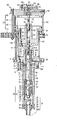
- a plunger case 1 comprises an upper case portion 4 and a lower case portion 5, both of which are detachably connected to each other by means of a bolt 2 and hermetically sealed by means of an O-ring 3.
- a plunger 6 is received in the plunger case 1 in such a manner that the plunger 6 is slidably supported and one end portion thereof (in the drawing, the lower end portion) is surrounded by the plunger case 1.
- a socket 7 is detachably coupled to the upper portion of the plunger 6 as viewed in the drawing.
- An O-ring 8 is interposed between the socket 7 and the plunger 6, and the socket 7 is slidable on the upper case portion 4 through a sleeve 9, a lip seal 10A and a dust seal 10B.
- the bellows 11 Fixed to the end face of the upper case portion 4 received in the lower case portion 5 is one end of the bellows 11 made of fluorine plastics or the like through an 0-ring 12 by means of a fastener 13 and a screw 14.
- the other end of the bellows 11 is solidly secured to the intermediate portion of the plunger 6 through an 0-ring 15.
- the fixation between the bellows 11 and the plunger 6 is effected by means of a pin 16 penetrating the plunger 6 and a box nut 17 rotatable relative to the plunger 6, abutted at the inner surface thereof against the pin 16 and threadedly coupled onto the lower end portion of the bellows 11.
- liquid 18 such as oil or the like
- the bellows 11 suitably expands or shrinks at all times without any unnecessary expansion or shrinkage in the radial direction thereof, whereby the pressure balance between the liquid 18 in the bellows 11 and the pressure-fed fluid flowing outside the bellows 11 is not lost, so that any harmful deformation of the bellows 11 due to a lost pressure balance, which would otherwise occur, can be avoided.
- a relatively large gap is formed between the outer periphery of the bellows 11 and the lower case portion 5 to serve as a flow path 5A for the pressure-fed fluid, and this flow path 5A is communicated with a discharge port 5B formed at the upper side surface of the lower case portion 5.
- a perforated plate 22 Solidly secured through a nut 21 to the inner end (the lower end in the drawing) of the plunger 6 is a receiving seat 20, and a perforated plate 22 is pressingly fixed and abutted against a stepped portion formed on the plunger 6 at a position upwardly spaced a predetermined distance apart from the lower end of the receiving seat 20.
- This perforated plate 22 is formed therein with a plurality of holes 23 being disposed on a circle concentric with the plunger 6 in a sectioned lotus root fashion as viewed in plan view, so that the pressure-fed fluid such as a coating composition including paint or the like can flow through the holes 23.
- a valve body 24 is a predetermined distance movably provided on the plunger 6 between the receiving seat 20 and the perforated plate 22.
- This valve body 24 comprises: a cylindrical member 25 having a flange forming a gap of a predetermined size between the outer diameter of the plunger 6 and itself; a plurality of V-shaped packings 26 formed of a material such as fluorine plastics, coupled onto the outer periphery of the cylindrical member 25 and closely attached to and slidable on a thin wall pipe 5C solidly secured at the peripheral surface thereof to the inner surface of the lower case portion 5; a nut 27 fixed to the upper end of the cylindrical member 25 for solidly securing the V-shaped packings 26 to the cylindrical member 25; and a valve seat 28 made of a sintered hard alloy or the like, having an inner diameter equal to the inner diameter of the cylindrical member 25 and fixed to the cylindrical member 25 in a manner to partially project from the undersurface of the cylindrical member 25.
- valve body 24 when the plunger 6 is moved downwardly, i.e. in a direction of closing an inlet valve to be described hereinafter, the valve body 24 as a whole is elevated until it abuts against the perforated plate 22 to separate the valve seat 28 from the receiving seat 20, the valve body 24 is opened whereby the upper and the lower portions of the valve body 24 are communicated with each other through a space formed between the valve seat 28 and the receiving seat 20, spaces formed within the inner peripheries of the valve seat 28 and the cylindrical member 25 and the holes 23 of the perforated plate 22. While, when the plunger 6 moves in the reverse direction, i.e.
- valve body 24 As a whole is lowered to abut the valve seat 28 against the receiving seat 20, whereby the valve body 24 is closed, so that the vertical communication through the valve body 24 can be blocked.
- the inner diameter D 3 of the pipe 5C is V - 2 of the effective diameter D 1 of the bellows 11, that is, the ratio between the entire area within the outer diameter of the cross section of the V-shaped packings 26 and the effective cross- sectional area of the bellows 11 becomes 2:1, and with this arrangement, the variation of volume of a portion below the V-shaped packings 26 due to the movement of the plunger 6 becomes two times the variation of volume of a portion above the V-shaped packings 26, i.e. two times the variation of volume on the side of the bellows 11.
- the valve seat 28 is closed to stop the flow-in of the fluid from below the V-shaped packings 26, and a difference between a decrease in the fluid receiving volume on the side of the bellows 11 due to the elevation of the plunger 6, i.e. the V-shaped packings 26 and an increase in the fluid receiving volume due to the shrinkage of the bellows 11 becomes sQ i being equal to the: quantity of discharge described above. Consequently, during both the elevating and lowering processes of the plunger 6, the fluid can be continuously discharged at the same quantity.
- the receiving seat 20, the nut 21, the perforated plate 22 and the valve body 24 constitute the discharge valve 29.
- valve seat 30 Inserted into the bottom end of the lower case portion 5 through an O-ring 31 is a valve seat 30 being of a hollow plug shape provided on the outer periphery of the forward end thereof with a threaded portion and formed at the bottom end thereof with an inlet port 30A.
- This valve seat 30 is fixed to the lower case portion 5 through a box nut 32.
- a ball support member 34 Interposed between the upper end of this valve seat 30 and a C-ring 33 fixed to the inner surface of the lower case portion 5 is a ball support member 34, which is of an inverted bottomed cylinder form and formed at the side wall and a part of the bottom surface thereof with a cut-away portion 35.
- a ball 36 is vertically movably received in the support member 34 and may block the upper end edge of a hole formed in the valve seat 30.
- the pressure-fed fluid such as the paint and the like can be sucked in through the valve seat 30, the cut-away portion 35 of the support member 34 and the C-ring 33.
- the ball 36 is lowered to abut against the seat valve 30, the flow of pressure-fed fluid is blocked.
- the valve seat 30, the C-ring 33, the ball support member 34 and the ball 36 constitute an inlet valve 37 of a ball valve type.
- This air cylinder 42 comprises: a case 47, in which an upper and a lower head covers 43 and 44 are securely connected to each other through a cylindrical body 45 by means of a tight bolt 46; and a piston 48 slidably received in this case 47.
- the bottom end of this piston 48 is connected to the plunger 6 by means of a connector 49 and a connecting bolt 50, so that the plunger 6 can be reciprocated in accordance with the movement of the piston 48.
- the aforesaid lower head cover 44 is provided therein with a path 52 for constantly feeding compressed air into a lower chamber 51 disposed at the undersurface of the head of the piston 48 and the upper head cover 43 is formed therein with a path 54 for supplying compressed air to a chamber 53 disposed at the top surface of the piston 48 when necessary.
- a change-over valve 55 is formed at the intermediate portion of the path 54, and, through the action of this change-over valve 55, compressed air is fed to the chamber 53 disposed at the top surface of the piston 48 through the path 54, or the air in the chamber 53 disposed at the top surface of the piston 48 is discharged to atmosphere through a filter 56.
- the change-over valve 55 comprises: a shaft 61 penetrating the box nut 57 threadably coupled into the piston 48, inserted at one end portion thereof into a blind hole 58 formed at the central portion of the piston 48 and wound around by a compression coil spring 60 confined between the box nut 57 and the inserted portion thereof; a pressure receiving member 62 secured to the shaft 61 at a position close to the upper end of the shaft 61 and slidable on the inner surface of the upper head cover 43; and a valve body 66 secured to the upper end portion of the shaft 61, and adapted to abut against a valve seat 63 provided in the upper head cover 43 at the intermediate portion of the path 54 and against a valve seat 65 provided on a cap 64 being secured to the upper head cover 43 and having the filter 56, respectively.
- a receiving base 67 being of a columnar form having a flange and a shock-absorbing spring 68, whereby, when the piston 47 is raised, a shock acting on the lower end of the shaft 61 is absorbed and an upwardly urging force is rendered to the shaft 61.
- the ratio between the pressure receiving areas of the top and the bottom surfaces of the piston 48 is determined to be 2:1, whereby, when pressures equal in value with each other act on the top and bottom surfaces of the piston 48, the piston 48 is automatically lowered.
- O-rings are provided at portions where the respective members of the cylinder 42 are connected to each other and hermetical seals are required.
- the plunger 6 connected to the piston 48 is lowered in unison with the downward movement of the piston 48, and the ball 36 of the inlet valve 37 is pressed against the valve seat 30 to block the path in accordance with the downward movement of the plunger 6, while, the valve body 24 of the discharge valve 29 is elevated by the pressure-fed fluid such as the paint or the like, the valve seat 28 is separated from the receiving seat 20, the fluid, which has been contained between the valve body 24 and the inlet valve 37, flows through the discharge valve 29 and enters the flow path 5A on the outer periphery of the bellows 11, and then, is discharged through the discharge port 5B.
- the socket 7 advances into the liquid 18 in accordance with the downward movement of the plunger 6, whereby the bellows 11 is expanded accordingly, however, because the outer diameter D 1 of the socket 7 is equal to the effective inner diameter D 2 of the bellows 11, whereby no variation occurs in pressure of the liquid 18 in the bellows 11 and in the space defined by the inner diameter of the lower case portion 5, so that any unusual deformation, breakage or other disadvantages can be avoided.
- the quantity of discharge through the discharge port 5B is made to be of the variation of volume due to the downward movement of the V-shaped packings 26 as aforesaid.
- the space upwardly of the inlet valve 37 is decreased in pressure in accordance with the upward movement of the valve body 24, whereby the ball 36 is raised to open the upper opening of the valve seat 30, so that the pressure-fed fluid sucked from a pressure-fed fluid tank, not shown, can flow into the lower space formed below the lower case portion 5 through the inlet valve 37.
- the quantity of discharge through the discharge port 5B is also made to be 2 of the variation of volume due to the downward movement of the V-shaped packings 26 as described above, so that during both the elevating and lowering processes of the plunger 6, the fluid can be continuously discharged at the same quantity.
- the urging force of the compression coil spring 60 for pushing the shaft 61 downwardly and the urging force of the compressed air acting downwardly on the upper surface of the pressure receiving member 62 are set at their combined value satisfactorily larger than the value of the urging force of the compressed air acting upwardly on the undersurface of the valve body 66 being abutted against the valve seat 63, whereby even when the elevation of the piston 48 is initiated, the shaft 61 of the change-over valve 55 is not moved upwardly, so that the blocking of the valve seat 63 can be continued. Consequently, the chamber 53 disposed at the top surface of the piston 48 is continued to be opened to atmosphere, so that the elevation of the piston 48 can be continued.
- the chamber 53 disposed at the top surface of the piston 48 is supplied with compressed air, whereby the lowering of the piston 48 is started due to the difference in pressure receiving area between the top and the bottom surfaces of the piston 48.
- valve body 66 since the valve body 66 is separated from the valve seat 63 having a small opening area, the undersurface of the valve body 66 as a whole forms a pressure receiving surface, and the pressure of the compressed air acting on this large pressure receiving surface renders an upwardly urging force to the shaft 61, so that the state where the shaft 61 tends to upwardly move, i.e. the blocking of the valve seat 65 on the side of atmosphere can be continued.
- the piston continues the downward movement, in accordance with which the plunger 6 also moves downwardly, so that the pressure-fed fluid can be discharged during downward movement of the plunger 6 in the same manner as described above.
- the piston 48 continues the downward movement, and, when the piston 48 reaches the stroke end, the urging force by the compressed spring 60 becomes very large in value, and this large urging force moves the shaft 61 downwardly to block the valve seat 63. Due to this blocking of the valve seat 63, the pressure receiving area becomes very small through the action of the valve seat 63, the upwardly urging force rendered to the valve body 66, i.e. the shaft 61 is decreased, so that the blocking of this valve seat 63 can be maintained. By this, the piston 48 is moved upwardly again. Thus, by repeating the above described action, the piston 48 and the plunger 6 are continuously reciprocated, so that the pressure-fed fluid can be discharged at the substantially same quantity during going and returning processes without any interruption.
- the liquid 18 such as oil for countering the pressure of the pressure-fed fluid to protect the bellows 11 is filled in the bellows 11 and the space defined by the inner diameter of the lower case portion 5 communicated with the interior of bellows 11.
- This filling operation is carried out such that the socket 7 provided on the upper portion of the plunger 6 is removed in the state where the plunger 6 is secured to the lower case portion 5 through the bellows 11, the liquid 18 of a given quantity is poured in through a gap formed between the plunger 6 and the inner periphery of the lower case portion 5, and then, the lower case portion 5 is slightly shaken, whereby foams and the like in the liquid 18 are easily removed, so that the foams and the like can be prevented from attaching to the ribs in the bellows 11.
- the inlet valve 37 provided in the lower case portion 5 of the plunger case 1 is formed of the ball valve
- the discharge valve 29 secured to the plunger 6 is formed of a valve including the valve body 24 movable relative to the plunger 6, whereby the use of expensive ball valves is limited to only one, so that a pump low in manufacturing costs can be provided.
- the pressure-fed fluid is not allowed to flow through the interior of the plunger 6, but; allowed to flow through the space formed around the outer periphery of the bellows 11, whereby, with this arrangement, the number of bellows 11 required is limited to only one, so that the manufacturing costs can be decreased and the pump as a whole can be rendered compact.
- the inlet valve 37 is formed of a ball valve
- the discharge valve 29 is constituted by a valve including the movable valve body 24, this embodiment can render the pump simplified in construction as compared with the case where there is adopted an arrangement reverse to this embodiment, i.e. the ball valve is provided on the discharge valve 29, because, in this embodiment, the operational association between the movement of the plunger 6 and the plunger case 1 can be directly utilized for the movement of the valve.
- the pressure-fed fluid such as the coating composition including paint or the like does not come into contact with the slide portion between the plunger 6 and the plunger case 1 so that, when the inorganic paint, zinc rich paint or the like is fed under pressure, the plunger 6, the plunger case 1 and so forth can be effectively protected against wear and a pump having general-purpose properties can be provided.
- the space around the outer periphery of the bellows 11 is formed into the flow path 5A and only the removal of the lower case portion 5 can expose the outer periphery of the bellows 11, so that the pressure-fed fluid such as the paint or the like adhered to the outer periphery of the bellows 11 can be readily removed.
- the liquid 18 for protecting the bellows 11 is filled in the interior of the bellows 11 having the relatively large space and gap, whereby the foams in this liquid 18 are very easily removable, so that the liquid 18 can be filled in at a high efficiency without using any special filling apparatus and the like.
- the plunger 6 can slide smoothly. Additionally, the discharge can be effected during going and returning processes of the plunger 6, fluctuations in the quantity of discharge are low, so that the pump can be suitably used for pressure feed to a coating spray gun and other applications requiring no fluctuation in the quantity of discharge.
- the flow of the pressure-fed flow is not in the rectilinear direction, but deviated at a right angle, so that the space required for piping in the vertical direction can be reduced and the pump as a whole can be rendered short in length.
- the cylinder 42 as the driving source can be automatically.switched by means of the change-over valve 55, so that the pump according to the present invention can be provided at a lower cost than the pump in which switching is electrically effected by means of sequence controls and the like.
- the outer diameter of the portion of the plunger 6, which is slidable on the plunger case 1 and projected into the portion communicated with the interior of the bellows 11 is made equal in value to the effective diameter D 2 of the bellows 11, so that the bellows 11 can avoid such disadvantages as an unusual deformation, breakage and the like due to the linear movement of the plunger 6.
- the driving source should not necessarily be limited to the air cylinder 42, but, may be any other means including a combination of an electric motor with a cam or a crank.
- the movement of the piston 48 and the like are explained in the vertical direction, however, there is no harm in explaining it in the horizontal direction.
- the discharge valve 29 and the inlet valve 37 should not necessarily be limited to the constructions shown in the above described embodiment, but, may be a construction in which the inlet valve 37 is formed of a poppet valve or the like for example.
- the present invention can provide a plunger pump being low in manufacturing costs, having general-purpose properties and capable of readily cleaning bellows.
Landscapes
- Engineering & Computer Science (AREA)
- Mechanical Engineering (AREA)
- General Engineering & Computer Science (AREA)
- Details Of Reciprocating Pumps (AREA)
- Reciprocating Pumps (AREA)
Claims (7)


Applications Claiming Priority (2)
| Application Number | Priority Date | Filing Date | Title |
|---|---|---|---|
| JP56040839A JPS57157078A (en) | 1981-03-20 | 1981-03-20 | Plunger pump |
| JP40839/81 | 1981-03-20 |
Publications (2)
| Publication Number | Publication Date |
|---|---|
| EP0060927A1 EP0060927A1 (fr) | 1982-09-29 |
| EP0060927B1 true EP0060927B1 (fr) | 1985-05-15 |
Family
ID=12591774
Family Applications (1)
| Application Number | Title | Priority Date | Filing Date |
|---|---|---|---|
| EP81109132A Expired EP0060927B1 (fr) | 1981-03-20 | 1981-10-28 | Pompe à piston plongeur |
Country Status (4)
| Country | Link |
|---|---|
| US (1) | US4436494A (fr) |
| EP (1) | EP0060927B1 (fr) |
| JP (1) | JPS57157078A (fr) |
| DE (1) | DE3170538D1 (fr) |
Cited By (1)
| Publication number | Priority date | Publication date | Assignee | Title |
|---|---|---|---|---|
| EP3390823A4 (fr) * | 2015-12-18 | 2019-01-16 | Graco Minnesota Inc. | Palier à soufflet interne |
Families Citing this family (16)
| Publication number | Priority date | Publication date | Assignee | Title |
|---|---|---|---|---|
| US4740141A (en) * | 1982-09-29 | 1988-04-26 | Intevep, S.A. | Plunger with composite retention valve |
| FR2602282B1 (fr) * | 1986-07-31 | 1988-09-23 | Cloup Jean | Perfectionnement aux dispositifs d'injection d'un produit additif dose dans un fluide principal |
| US4738600A (en) * | 1987-03-05 | 1988-04-19 | Dresser-Rand Company | Lubricating system |
| US4784584A (en) * | 1987-07-17 | 1988-11-15 | Oil-Rite Corporation | Metering device |
| US4784578A (en) * | 1987-07-17 | 1988-11-15 | Oil-Rite Corporation | Metering device |
| US4995793A (en) * | 1987-10-21 | 1991-02-26 | Product Research And Development | Reverse osmosis system and automatic cycling booster pump therefor |
| FR2745858B1 (fr) * | 1996-03-07 | 2000-12-22 | Ile De Rech Ody Soc Civ | Perfectionnenents apportes aux pompes doseuses |
| US7118352B2 (en) * | 2003-09-17 | 2006-10-10 | Oil-Rite Corporation | Hydraulic metering device |
| US8632322B2 (en) * | 2006-01-30 | 2014-01-21 | Ingersoll-Rand Company | Plunger pump with atmospheric bellows |
| CN104791238A (zh) * | 2014-01-17 | 2015-07-22 | 沈如华 | 一种高效率色浆调色泵 |
| CN104131973A (zh) * | 2014-07-17 | 2014-11-05 | 常州爱普超高压液压系统有限公司 | 可连续出油的气动增压泵 |
| TW201727079A (zh) * | 2015-12-18 | 2017-08-01 | 葛萊兒明尼蘇達股份有限公司 | 波紋管安裝及保留方法 |
| CN108368841B (zh) * | 2015-12-18 | 2021-03-09 | 固瑞克明尼苏达有限公司 | 波纹管的防转动结构 |
| CN108368843B (zh) | 2015-12-18 | 2020-06-05 | 固瑞克明尼苏达有限公司 | 波纹管减压阀 |
| DE102016210737A1 (de) * | 2016-06-16 | 2017-12-21 | Robert Bosch Gmbh | Förderpumpe für kryogene Kraftstoffe |
| US10473223B2 (en) | 2017-03-02 | 2019-11-12 | Oil-Rite Corporation | Evacuation valve |
Family Cites Families (14)
| Publication number | Priority date | Publication date | Assignee | Title |
|---|---|---|---|---|
| BE570184A (fr) * | ||||
| US2980080A (en) | 1961-04-18 | Karl-evert a | ||
| US1595939A (en) | 1923-01-19 | 1926-08-10 | William S Hukill | Fluid-pressure prime mover |
| US2342906A (en) * | 1941-04-01 | 1944-02-29 | Cecil W Smith | Pump |
| US2668656A (en) * | 1944-12-19 | 1954-02-09 | Jr Eugene T Booth | Sylphon sealed pump |
| FR1162157A (fr) * | 1956-07-21 | 1958-09-09 | Matairco Soc | Groupe hydro-pneumatique et installations utilisant un tel groupe, pour la commande pneumatique d'appareils hydrauliques |
| US3094938A (en) | 1961-06-19 | 1963-06-25 | Aro Corp | Pump structure |
| DE1212372B (de) | 1963-11-04 | 1966-03-10 | Teves Kg Alfred | Gleitflaechenschutz fuer hydraulische Zylinder |
| DE1567313A1 (de) * | 1967-08-22 | 1970-04-16 | Haensel Otto Gmbh | Foerdereinrichtung fuer aus einer Kochmaschine kommende Zuckermassen |
| US3536424A (en) * | 1968-11-12 | 1970-10-27 | Hydro Seal Ltd | Pump and piston assembly therefor |
| US3632233A (en) * | 1970-07-09 | 1972-01-04 | George C Graham | Fluid pump apparatus and system |
| JPS5233576Y2 (fr) * | 1971-06-03 | 1977-07-30 | ||
| DE2129588C3 (de) * | 1971-06-15 | 1975-10-30 | Chemie Und Filter Gmbh, Verfahrenstechnik Kg, 6900 Heidelberg | Dosierpumpe |
| DE2253288A1 (de) * | 1972-10-31 | 1974-05-09 | Guenter Meyenburg | Pneumatisch betriebene hochdruckpumpe fuer fluessigkeiten und gase |
-
1981
- 1981-03-20 JP JP56040839A patent/JPS57157078A/ja active Pending
- 1981-10-28 EP EP81109132A patent/EP0060927B1/fr not_active Expired
- 1981-10-28 DE DE8181109132T patent/DE3170538D1/de not_active Expired
- 1981-10-29 US US06/316,169 patent/US4436494A/en not_active Expired - Fee Related
Cited By (1)
| Publication number | Priority date | Publication date | Assignee | Title |
|---|---|---|---|---|
| EP3390823A4 (fr) * | 2015-12-18 | 2019-01-16 | Graco Minnesota Inc. | Palier à soufflet interne |
Also Published As
| Publication number | Publication date |
|---|---|
| DE3170538D1 (en) | 1985-06-20 |
| US4436494A (en) | 1984-03-13 |
| EP0060927A1 (fr) | 1982-09-29 |
| JPS57157078A (en) | 1982-09-28 |
Similar Documents
| Publication | Publication Date | Title |
|---|---|---|
| EP0060927B1 (fr) | Pompe à piston plongeur | |
| US3330217A (en) | Pump | |
| US4775303A (en) | Pump having adjustable packing | |
| EP0309240B1 (fr) | Pompe et soupape | |
| US3953154A (en) | Pressure control and unloader valve | |
| US3957399A (en) | Diaphragm pump | |
| US4139469A (en) | Fluid control mechanism | |
| US4365745A (en) | Diaphragm pump | |
| US5346037A (en) | Packing nut and rod guide for piston paint pumps | |
| US4239463A (en) | Reciprocating plunger pump with improved liquid end valve assembly | |
| CA2244849A1 (fr) | Pompe de distribution de fluide a commande manuelle | |
| WO2000068574A1 (fr) | Vanne multifonction | |
| US4594057A (en) | Injector pump | |
| EP0462386B1 (fr) | Pompe à piston à mouvement alternatif à double effet | |
| US4830232A (en) | Fluid dispenser valve with rolling diaphragm | |
| US20060037465A1 (en) | Hydraulic machine | |
| US5339932A (en) | Apparatus and method to cushion movement of a member | |
| EP0666420B1 (fr) | Dispositif d'actionnement de piston à pression de fluide | |
| CA1221874A (fr) | Piston a clapet antiretour composite | |
| US3366379A (en) | Air spring | |
| US5927178A (en) | Press driven tool actuator module | |
| EP0488781B1 (fr) | Dispositif de pompage et des réservoirs pourvus d'un tel dispositif | |
| CA1236344A (fr) | Piston d'emboutissage commande a l'azote gazeux | |
| US3076417A (en) | Positive displacement pump | |
| US5720600A (en) | Sucker rod pump |
Legal Events
| Date | Code | Title | Description |
|---|---|---|---|
| PUAI | Public reference made under article 153(3) epc to a published international application that has entered the european phase |
Free format text: ORIGINAL CODE: 0009012 |
|
| 17P | Request for examination filed |
Effective date: 19811028 |
|
| AK | Designated contracting states |
Designated state(s): BE DE FR GB IT LU NL |
|
| ITF | It: translation for a ep patent filed | ||
| GRAA | (expected) grant |
Free format text: ORIGINAL CODE: 0009210 |
|
| AK | Designated contracting states |
Designated state(s): BE DE FR GB IT LU NL |
|
| REF | Corresponds to: |
Ref document number: 3170538 Country of ref document: DE Date of ref document: 19850620 |
|
| ET | Fr: translation filed | ||
| PG25 | Lapsed in a contracting state [announced via postgrant information from national office to epo] |
Ref country code: LU Free format text: LAPSE BECAUSE OF NON-PAYMENT OF DUE FEES Effective date: 19851031 |
|
| PLBE | No opposition filed within time limit |
Free format text: ORIGINAL CODE: 0009261 |
|
| STAA | Information on the status of an ep patent application or granted ep patent |
Free format text: STATUS: NO OPPOSITION FILED WITHIN TIME LIMIT |
|
| 26N | No opposition filed | ||
| PGFP | Annual fee paid to national office [announced via postgrant information from national office to epo] |
Ref country code: FR Payment date: 19891010 Year of fee payment: 9 |
|
| PGFP | Annual fee paid to national office [announced via postgrant information from national office to epo] |
Ref country code: BE Payment date: 19891017 Year of fee payment: 9 |
|
| PGFP | Annual fee paid to national office [announced via postgrant information from national office to epo] |
Ref country code: LU Payment date: 19891019 Year of fee payment: 9 |
|
| ITTA | It: last paid annual fee | ||
| PGFP | Annual fee paid to national office [announced via postgrant information from national office to epo] |
Ref country code: NL Payment date: 19891031 Year of fee payment: 9 Ref country code: GB Payment date: 19891031 Year of fee payment: 9 |
|
| PGFP | Annual fee paid to national office [announced via postgrant information from national office to epo] |
Ref country code: DE Payment date: 19891130 Year of fee payment: 9 |
|
| PG25 | Lapsed in a contracting state [announced via postgrant information from national office to epo] |
Ref country code: GB Effective date: 19901028 |
|
| PG25 | Lapsed in a contracting state [announced via postgrant information from national office to epo] |
Ref country code: BE Effective date: 19901031 |
|
| BERE | Be: lapsed |
Owner name: NAGANO KEIKI SEISAKUSHO LTD. Effective date: 19901031 |
|
| PG25 | Lapsed in a contracting state [announced via postgrant information from national office to epo] |
Ref country code: NL Effective date: 19910501 |
|
| NLV4 | Nl: lapsed or anulled due to non-payment of the annual fee | ||
| GBPC | Gb: european patent ceased through non-payment of renewal fee | ||
| PG25 | Lapsed in a contracting state [announced via postgrant information from national office to epo] |
Ref country code: FR Effective date: 19910628 |
|
| PG25 | Lapsed in a contracting state [announced via postgrant information from national office to epo] |
Ref country code: DE Effective date: 19910702 |
|
| REG | Reference to a national code |
Ref country code: FR Ref legal event code: ST |