EP0060964B1 - Appareil pour positionner une bobine de bande métallique en face d'un dévidoir - Google Patents
Appareil pour positionner une bobine de bande métallique en face d'un dévidoir Download PDFInfo
- Publication number
- EP0060964B1 EP0060964B1 EP19810890179 EP81890179A EP0060964B1 EP 0060964 B1 EP0060964 B1 EP 0060964B1 EP 19810890179 EP19810890179 EP 19810890179 EP 81890179 A EP81890179 A EP 81890179A EP 0060964 B1 EP0060964 B1 EP 0060964B1
- Authority
- EP
- European Patent Office
- Prior art keywords
- measuring
- lifting
- sheet metal
- stop
- reel
- Prior art date
- Legal status (The legal status is an assumption and is not a legal conclusion. Google has not performed a legal analysis and makes no representation as to the accuracy of the status listed.)
- Expired
Links
Images
Classifications
-
- B—PERFORMING OPERATIONS; TRANSPORTING
- B21—MECHANICAL METAL-WORKING WITHOUT ESSENTIALLY REMOVING MATERIAL; PUNCHING METAL
- B21C—MANUFACTURE OF METAL SHEETS, WIRE, RODS, TUBES, PROFILES OR LIKE SEMI-MANUFACTURED PRODUCTS OTHERWISE THAN BY ROLLING; AUXILIARY OPERATIONS USED IN CONNECTION WITH METAL-WORKING WITHOUT ESSENTIALLY REMOVING MATERIAL
- B21C47/00—Winding-up, coiling or winding-off metal wire, metal band or other flexible metal material characterised by features relevant to metal processing only
- B21C47/24—Transferring coils to or from winding apparatus or to or from operative position therein; Preventing uncoiling during transfer
-
- B—PERFORMING OPERATIONS; TRANSPORTING
- B65—CONVEYING; PACKING; STORING; HANDLING THIN OR FILAMENTARY MATERIAL
- B65H—HANDLING THIN OR FILAMENTARY MATERIAL, e.g. SHEETS, WEBS, CABLES
- B65H19/00—Changing the web roll
- B65H19/10—Changing the web roll in unwinding mechanisms or in connection with unwinding operations
- B65H19/12—Lifting, transporting, or inserting the web roll; Removing empty core
-
- B—PERFORMING OPERATIONS; TRANSPORTING
- B65—CONVEYING; PACKING; STORING; HANDLING THIN OR FILAMENTARY MATERIAL
- B65H—HANDLING THIN OR FILAMENTARY MATERIAL, e.g. SHEETS, WEBS, CABLES
- B65H2301/00—Handling processes for sheets or webs
- B65H2301/40—Type of handling process
- B65H2301/41—Winding, unwinding
- B65H2301/417—Handling or changing web rolls
- B65H2301/4171—Handling web roll
- B65H2301/4172—Handling web roll by circumferential portion, e.g. rolling on circumference
Definitions
- the invention relates to a device for aligning a coil of sheet metal with respect to a reel, consisting of a lifting table, the lifting drive of which can be actuated via a control depending on the position of two measuring stops that can be displaced relative to one another, which is formed on the one hand by the lifting table and on the other hand by at least one measuring sensor are.
- the two measuring stops can be moved in opposite directions and symmetrically to the axis of the reel, so that the collar lying on the lifting table is aligned with the reel when the counter stop is reached. Since the sensor forming the measuring stop and the lifting table forming the other measuring stop are always equidistant from the reel axis due to their opposite movement, the distance between the two measuring stops must correspond to the diameter of the sheet metal bundle when the measuring sensor, for example given by a light barrier, responds the alignment of the coil with respect to the reel axis results.
- the measuring stop designed as a measuring sensor is first placed on the coil of sheet metal and then the distance of the lifting table from the reel axis is compared with the distance between the sensor and the reel axis .
- the two measuring stops given by the sensor and the lifting table are each connected to a measuring device for their distance from the reel axis, so that the drive for the lifting table can be switched off via a control if the two measuring devices indicate the same values.
- the lifting table must therefore be raised or lowered to align the sheet coil with the reel until this condition is met.
- a disadvantage of these known devices is that either the adjustment path of both measuring stops, that is to say the stroke of the lifting table and the displacement path of the measuring sensor, or that both measuring stops have to be moved in opposite directions, which requires a comparatively complex and therefore prone to failure.
- the actual coil diameter is not recorded in terms of size, so that the control system cannot take the coil size into account.
- the drive and speed of the individual work steps must therefore be fixed and cannot be adapted to the size of the respective bundle.
- the invention is therefore based on the object of avoiding these deficiencies and improving a device of the type described in such a way that alignment of the sheet metal coils with respect to a reel is ensured with simple constructional means, with the control being able to be adapted to different coil diameters.
- the invention solves the problem in that one of the two measuring stops is connected to a measuring device connected to the control for its adjustment path, that the other measuring stop is in a predetermined basic position at least during the adjustment path measurement and that the alignment dimension for the sheet metal bundle is by means of a Calculator is determined from the difference between the specified basic distance between the two measuring stops and the measured adjustment path.
- the predefined basic position of the measuring stop that is not to be adjusted during the measurement nevertheless makes it possible to determine the diameter for the sheet metal bundle, because the bundle diameter results from the difference between the original distance between the two measuring stops and the adjustment path of the displaceable measuring stop.
- the required stroke is also determined, which lifts the sheet metal bundle to the axis height of the reel.
- the measurement of the collar diameter offers the advantage that, for example, the lifting speed, depending on the collar diameter, can be slowed down just before reaching the alignment position in order to ensure the smallest possible tolerances.
- the coil weight can be determined via the coil diameter, which also allows a favorable adaptation of the drive to the sheet metal coil to be treated.
- the diameter can be recorded separately from the reel, so that the values obtained can already be used for the transport of the coil to the reel.
- the measuring device consists of an incremental scale with a scanning unit and a counter for the scanning pulses of the scanning unit connected to a computer, because the digital one Measurement a measurement accuracy specified by the incremental scale can be easily maintained and the scanning pulses counted in the counter can be used directly for processing in the computer.
- This computer belonging to the controller then outputs the desired calculation results or control pulses for controlling the individual drives in accordance with its program.
- the lifting table can advantageously be used as adjustable measuring stop can be connected to a measuring device for the stroke. If the immovable measuring stop is a light barrier, a stop pulse can be obtained for the counter of the measuring device when the light barrier is interrupted, making any mechanical switch superfluous. If sheet metal coils with very different diameters are to be detected, it is advisable to provide two or more light barriers with a mutual distance in the lifting direction of the lifting table in order to be able to limit the lifting table to a maximum. With such a design, the sheet metal collar only needs to be raised or lowered regardless of its diameter to the next light barrier, as a result of which the maximum stroke is limited to the distance between two successive light barriers.
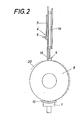
- this counterstop is designed as an adjustable pressure stamp.
- the protruding tape start is pressed against the collar by means of the pressure stamp, thus ensuring the detection of the actual coil diameter.
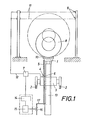
- the lifting table 1 of a trolley 3 which can be moved on rails 2 is connected to a measuring device 4 for the lifting path of the lifting table 1.
- This measuring device consists of an incremental scale 5, which can be designed, for example, as a toothed rack, and a scanning unit 6, which is connected to a counter 7.
- the scanning unit for the incremental scale emits scanning pulses to the counter 7 when the scale marks are passed, which counts these scanning pulses. The sum of the scanning pulses therefore corresponds to the number of measuring marks of the incremental scale passed over by the scanning unit 6 and can be evaluated as a distance dimension for a given measuring mark distance.
- the scanning unit 6 can be designed differently, there are particularly simple conditions for the device shown if the scanning unit comprises the incremental scale designed as a toothed rack and carries a light source on one fork leg and a photoelectric element on the other fork leg. The light beam between the light source and the photoelectric element is interrupted by the teeth of the rack, whereby the required counting pulses are obtained.
- two measuring stops 9 and 10 are required, of which one 10 is formed by the lifting table 1 and the other by at least one measuring sensor, one being a measuring sensor Offers light barrier 11 as particularly advantageous. If the sheet metal collar 8 is now raised with the aid of the lifting table 1 from a basic position determined by the starting position of the lifting table 1 until the stationary measuring stop 9 is reached by the collar, the counter 7 of the measuring device 4 can be stopped via the measuring stop. Since the distance of the lifting table 1 in its initial position from the stationary measuring stop is structurally predetermined and known, the adjustment path of the lifting table 1 is a measure from which the collar diameter can be derived.
- the collar diameter can be directly at the counter when the fixed measuring stop is reached be read. If the sheet metal collar 8 reaches a light barrier 11 when it is raised, the light beam is interrupted, which can be used to pass on a stop pulse to the counter 7 via a line 12.
- the diameter detection for the sheet bundle 8 resting on the lifting table 1 does not yet ensure the alignment of this sheet bundle with respect to the reel axis.
- the required stroke distance for the lifting table 1 can, however, be calculated from the diameter, because the distance of the reel axis from the coil carriage 3 and thus from the lifting table 1 is predetermined in its initial position.
- the status of the counter 7 can be read into a computer 14 which, on the basis of its program, calculates the lifting path of the lifting table 1 necessary for aligning the sheet metal bundle with respect to the reel axis and the calculation result or a corresponding one Passes control signal to an actuator 15 for a control valve 16 in the supply line 17 of the cylinder 13.
- the determined bundle diameter can also be used for additional tax tasks.
- the coil diameter the initial number of revolutions required for a desired take-off speed for the reel is given.
- the coil weight depends on the coil diameter, which allows weight-dependent drive control via the diameter detection.
- the lifting speed can be changed over from rapid to crawling in a favorable manner, so that the desired lifting position can be approached precisely.
Landscapes
- Engineering & Computer Science (AREA)
- Mechanical Engineering (AREA)
- Controlling Rewinding, Feeding, Winding, Or Abnormalities Of Webs (AREA)
Claims (6)
Applications Claiming Priority (2)
| Application Number | Priority Date | Filing Date | Title |
|---|---|---|---|
| AT1288/81 | 1981-03-19 | ||
| AT128881A AT368913B (de) | 1981-03-19 | 1981-03-19 | Vorrichtung zum ausrichten eines blechbundes gegenueber einem haspel |
Publications (2)
| Publication Number | Publication Date |
|---|---|
| EP0060964A1 EP0060964A1 (fr) | 1982-09-29 |
| EP0060964B1 true EP0060964B1 (fr) | 1984-05-30 |
Family
ID=3510648
Family Applications (1)
| Application Number | Title | Priority Date | Filing Date |
|---|---|---|---|
| EP19810890179 Expired EP0060964B1 (fr) | 1981-03-19 | 1981-10-23 | Appareil pour positionner une bobine de bande métallique en face d'un dévidoir |
Country Status (3)
| Country | Link |
|---|---|
| EP (1) | EP0060964B1 (fr) |
| AT (1) | AT368913B (fr) |
| DE (1) | DE3163914D1 (fr) |
Families Citing this family (4)
| Publication number | Priority date | Publication date | Assignee | Title |
|---|---|---|---|---|
| JP2559444B2 (ja) * | 1988-02-04 | 1996-12-04 | 武田薬品工業株式会社 | シート状成形材料の巻取装置 |
| DE4429482A1 (de) * | 1994-08-19 | 1996-02-22 | Hacoba Textilmaschinen | Verfahren zum Einspannen eines Wickeltragbaums |
| CN111922119A (zh) * | 2020-08-19 | 2020-11-13 | 昆山峤川电气科技有限公司 | 冷轧机组自动上料系统及其操作方法 |
| CN116833248A (zh) * | 2023-04-24 | 2023-10-03 | 中冶南方工程技术有限公司 | 地辊站及其操作方法、钢卷处置机组 |
Family Cites Families (4)
| Publication number | Priority date | Publication date | Assignee | Title |
|---|---|---|---|---|
| DE1266094B (de) * | 1966-08-18 | 1968-04-11 | Demag Ag | Einrichtung zur automatischen Zentrierung eines Metallband-Bundes zum Dorn einer Haspelstation |
| AT277124B (de) * | 1967-11-06 | 1969-12-10 | Voest Ag | Vorrichtung zum Aufbringen von Bunden auf eine Abwickelhaspel |
| DE2136791B2 (de) * | 1971-07-23 | 1973-05-03 | Ungerer Geb. Dollinger, Irma, 7530 Pforzheim | Vorrichtung zum beschicken eines abwickelhaspels |
| US4194434A (en) * | 1977-02-17 | 1980-03-25 | Hoogovens Ijmuiden, B.V. | Device for controlling a longitudinally movable driving means |
-
1981
- 1981-03-19 AT AT128881A patent/AT368913B/de not_active IP Right Cessation
- 1981-10-23 EP EP19810890179 patent/EP0060964B1/fr not_active Expired
- 1981-10-23 DE DE8181890179T patent/DE3163914D1/de not_active Expired
Also Published As
| Publication number | Publication date |
|---|---|
| EP0060964A1 (fr) | 1982-09-29 |
| DE3163914D1 (en) | 1984-07-05 |
| ATA128881A (de) | 1982-04-15 |
| AT368913B (de) | 1982-11-25 |
Similar Documents
| Publication | Publication Date | Title |
|---|---|---|
| EP0511488A1 (fr) | Plieuse de papier avec des rouleaux plieurs réglables | |
| DE2952253C2 (fr) | ||
| DE3304475A1 (de) | Automatisierte messskala | |
| DE69304485T2 (de) | Messvorrichtung für Blechbiegewinkel | |
| EP0303722B1 (fr) | Procédé et dispositif pour la détection et traitement de défauts dans des pans d'étoffe | |
| DE3629515C2 (de) | Sicherheitsvorrichtung für eine Presse | |
| EP0060964B1 (fr) | Appareil pour positionner une bobine de bande métallique en face d'un dévidoir | |
| EP0048382B1 (fr) | Dispositif de prise de vues radiographiques comportant un porte-film déplaçable d'une position de garage à une position de prise de vue | |
| DE2601274A1 (de) | Detektorvorrichtung | |
| EP0066933B1 (fr) | Appareil à cible radiographique | |
| DE2148066A1 (de) | Durchmesser-Meßgerät für Werkzeugmaschinen | |
| DE3217815C2 (de) | Abtastvorrichtung zur Ermittlung von Warenbahnnähten | |
| DE19548509C2 (de) | Verfahren und Vorrichtung zur Bestimmung der Position eines Steuerstabes einer Kernkraftanlage | |
| DE1534093C3 (de) | Fahrbare Vorrichtung zum kontinuierlich fortschreitenden Korrigieren der Lage eines Gleises | |
| DE2054643A1 (de) | Vorrichtung zur Bestimmung von Abmessungen | |
| DE1531085B1 (de) | Vorrichtung zum Zentrieren von Blechbunden oder anderem,schwerem Foerdergut an einer Aufsetzstelle eines Tragbalkenfoerderers | |
| DE2335340B2 (de) | Digitalgesteuerte aufzeichnungsvorrichtung | |
| DD228492A1 (de) | Einrichtung zur register-einstellung an druckmaschinen | |
| DE3829279C2 (fr) | ||
| DE2652200A1 (de) | Einrichtung zur registereinstellung an einer bahnfoerdernden maschine | |
| DE9203930U1 (de) | Papierfalzmaschine mit einstellbaren Falzwalzen | |
| DE1448385B2 (de) | Meßeinrichtung zur kontinuierlichen Messung der jeweiligen Durchlauflänge eines bewegten Bandes | |
| DE3311203A1 (de) | Verfahren zum reproduzieren einer bezugsposition | |
| DE1463646C3 (de) | Elektrische Antriebsanordnung zum Synchronisieren der Geschwindigkeit einer Warenbahn und der Umfangsgeschwindigkeit einer anzuschließenden Rolle | |
| EP1001325B1 (fr) | Procédé et appareil pour le positionnement d'un objet |
Legal Events
| Date | Code | Title | Description |
|---|---|---|---|
| PUAI | Public reference made under article 153(3) epc to a published international application that has entered the european phase |
Free format text: ORIGINAL CODE: 0009012 |
|
| AK | Designated contracting states |
Designated state(s): BE CH DE FR GB IT LU NL SE |
|
| 17P | Request for examination filed |
Effective date: 19821104 |
|
| ITF | It: translation for a ep patent filed | ||
| GRAA | (expected) grant |
Free format text: ORIGINAL CODE: 0009210 |
|
| AK | Designated contracting states |
Designated state(s): BE CH DE FR GB IT LI LU NL SE |
|
| REF | Corresponds to: |
Ref document number: 3163914 Country of ref document: DE Date of ref document: 19840705 |
|
| ET | Fr: translation filed | ||
| PGFP | Annual fee paid to national office [announced via postgrant information from national office to epo] |
Ref country code: DE Payment date: 19841003 Year of fee payment: 4 |
|
| PGFP | Annual fee paid to national office [announced via postgrant information from national office to epo] |
Ref country code: FR Payment date: 19841004 Year of fee payment: 4 |
|
| PGFP | Annual fee paid to national office [announced via postgrant information from national office to epo] |
Ref country code: CH Payment date: 19841030 Year of fee payment: 4 |
|
| PG25 | Lapsed in a contracting state [announced via postgrant information from national office to epo] |
Ref country code: LU Free format text: LAPSE BECAUSE OF NON-PAYMENT OF DUE FEES Effective date: 19841031 |
|
| PGFP | Annual fee paid to national office [announced via postgrant information from national office to epo] |
Ref country code: NL Payment date: 19841031 Year of fee payment: 4 |
|
| PGFP | Annual fee paid to national office [announced via postgrant information from national office to epo] |
Ref country code: SE Payment date: 19841231 Year of fee payment: 4 Ref country code: BE Payment date: 19841231 Year of fee payment: 4 |
|
| PLBI | Opposition filed |
Free format text: ORIGINAL CODE: 0009260 |
|
| 26 | Opposition filed |
Opponent name: SMS SCHLOEMANN-SIEMAG AG Effective date: 19850222 |
|
| NLR1 | Nl: opposition has been filed with the epo |
Opponent name: SMS SCHLOEMANN-SIEMAG AG. |
|
| RDAG | Patent revoked |
Free format text: ORIGINAL CODE: 0009271 |
|
| STAA | Information on the status of an ep patent application or granted ep patent |
Free format text: STATUS: PATENT REVOKED |
|
| 27W | Patent revoked |
Effective date: 19850826 |
|
| REG | Reference to a national code |
Ref country code: CH Ref legal event code: PL |
|
| NLR2 | Nl: decision of opposition | ||
| GBPR | Gb: patent revoked under art. 102 of the ep convention designating the uk as contracting state | ||
| BERE | Be: lapsed |
Owner name: VOEST-ALPINE A.G. Effective date: 19851023 |
|
| REG | Reference to a national code |
Ref country code: FR Ref legal event code: ST |
|
| EUG | Se: european patent has lapsed |
Ref document number: 81890179.5 Effective date: 19860730 |