EP0061074B1 - Appareil pour le prélèvement et l'analyse des aérosols atmosphériques absorbés par les êtres vivants - Google Patents
Appareil pour le prélèvement et l'analyse des aérosols atmosphériques absorbés par les êtres vivants Download PDFInfo
- Publication number
- EP0061074B1 EP0061074B1 EP82101928A EP82101928A EP0061074B1 EP 0061074 B1 EP0061074 B1 EP 0061074B1 EP 82101928 A EP82101928 A EP 82101928A EP 82101928 A EP82101928 A EP 82101928A EP 0061074 B1 EP0061074 B1 EP 0061074B1
- Authority
- EP
- European Patent Office
- Prior art keywords
- spirometer
- air
- sampling
- aerosols
- flow
- Prior art date
- Legal status (The legal status is an assumption and is not a legal conclusion. Google has not performed a legal analysis and makes no representation as to the accuracy of the status listed.)
- Expired
Links
- 239000000443 aerosol Substances 0.000 title claims description 17
- 238000005070 sampling Methods 0.000 title claims description 17
- 238000006073 displacement reaction Methods 0.000 claims description 3
- 239000003570 air Substances 0.000 description 50
- 239000002245 particle Substances 0.000 description 15
- 239000000523 sample Substances 0.000 description 8
- 230000008021 deposition Effects 0.000 description 4
- 238000010586 diagram Methods 0.000 description 4
- 238000000034 method Methods 0.000 description 4
- 239000012080 ambient air Substances 0.000 description 3
- 238000004458 analytical method Methods 0.000 description 3
- 230000004913 activation Effects 0.000 description 2
- 239000005427 atmospheric aerosol Substances 0.000 description 2
- 238000009833 condensation Methods 0.000 description 2
- 230000005494 condensation Effects 0.000 description 2
- 230000004907 flux Effects 0.000 description 2
- 238000010438 heat treatment Methods 0.000 description 2
- 239000012528 membrane Substances 0.000 description 2
- 239000002184 metal Substances 0.000 description 2
- 229910052751 metal Inorganic materials 0.000 description 2
- 238000003921 particle size analysis Methods 0.000 description 2
- 230000001105 regulatory effect Effects 0.000 description 2
- 210000002345 respiratory system Anatomy 0.000 description 2
- XLYOFNOQVPJJNP-UHFFFAOYSA-N water Substances O XLYOFNOQVPJJNP-UHFFFAOYSA-N 0.000 description 2
- 238000010521 absorption reaction Methods 0.000 description 1
- 238000004378 air conditioning Methods 0.000 description 1
- 238000001479 atomic absorption spectroscopy Methods 0.000 description 1
- 238000006243 chemical reaction Methods 0.000 description 1
- 238000004737 colorimetric analysis Methods 0.000 description 1
- 238000004891 communication Methods 0.000 description 1
- 230000001609 comparable effect Effects 0.000 description 1
- 230000001010 compromised effect Effects 0.000 description 1
- 239000013256 coordination polymer Substances 0.000 description 1
- 230000006735 deficit Effects 0.000 description 1
- 238000013461 design Methods 0.000 description 1
- 238000010790 dilution Methods 0.000 description 1
- 239000012895 dilution Substances 0.000 description 1
- 230000000694 effects Effects 0.000 description 1
- 238000005516 engineering process Methods 0.000 description 1
- 230000007613 environmental effect Effects 0.000 description 1
- 238000002474 experimental method Methods 0.000 description 1
- 239000012530 fluid Substances 0.000 description 1
- 238000005194 fractionation Methods 0.000 description 1
- 239000011491 glass wool Substances 0.000 description 1
- 238000003306 harvesting Methods 0.000 description 1
- 210000004072 lung Anatomy 0.000 description 1
- 238000004519 manufacturing process Methods 0.000 description 1
- 150000002739 metals Chemical class 0.000 description 1
- 230000001575 pathological effect Effects 0.000 description 1
- 238000003969 polarography Methods 0.000 description 1
- 238000000190 proton-induced X-ray emission spectroscopy Methods 0.000 description 1
- 238000011160 research Methods 0.000 description 1
- 230000000241 respiratory effect Effects 0.000 description 1
- 230000036387 respiratory rate Effects 0.000 description 1
- 230000000630 rising effect Effects 0.000 description 1
- 239000000243 solution Substances 0.000 description 1
- 229910001220 stainless steel Inorganic materials 0.000 description 1
- 239000010935 stainless steel Substances 0.000 description 1
- 230000001360 synchronised effect Effects 0.000 description 1
- 230000009897 systematic effect Effects 0.000 description 1
- 238000011144 upstream manufacturing Methods 0.000 description 1
Images


Classifications
-
- A—HUMAN NECESSITIES
- A61—MEDICAL OR VETERINARY SCIENCE; HYGIENE
- A61B—DIAGNOSIS; SURGERY; IDENTIFICATION
- A61B5/00—Measuring for diagnostic purposes; Identification of persons
- A61B5/08—Measuring devices for evaluating the respiratory organs
-
- A—HUMAN NECESSITIES
- A61—MEDICAL OR VETERINARY SCIENCE; HYGIENE
- A61B—DIAGNOSIS; SURGERY; IDENTIFICATION
- A61B5/00—Measuring for diagnostic purposes; Identification of persons
- A61B5/08—Measuring devices for evaluating the respiratory organs
- A61B5/082—Evaluation by breath analysis, e.g. determination of the chemical composition of exhaled breath
-
- A—HUMAN NECESSITIES
- A61—MEDICAL OR VETERINARY SCIENCE; HYGIENE
- A61B—DIAGNOSIS; SURGERY; IDENTIFICATION
- A61B5/00—Measuring for diagnostic purposes; Identification of persons
- A61B5/08—Measuring devices for evaluating the respiratory organs
- A61B5/091—Measuring volume of inspired or expired gases, e.g. to determine lung capacity
- A61B5/093—Measuring volume of inspired or expired gases, e.g. to determine lung capacity the gases being exhaled into, or inhaled from, an expansible chamber, e.g. bellows or expansible bag
- A61B5/095—Measuring volume of inspired or expired gases, e.g. to determine lung capacity the gases being exhaled into, or inhaled from, an expansible chamber, e.g. bellows or expansible bag within a rigid container, e.g. the boundary being formed by a liquid surface
-
- G—PHYSICS
- G01—MEASURING; TESTING
- G01N—INVESTIGATING OR ANALYSING MATERIALS BY DETERMINING THEIR CHEMICAL OR PHYSICAL PROPERTIES
- G01N1/00—Sampling; Preparing specimens for investigation
- G01N1/02—Devices for withdrawing samples
- G01N1/22—Devices for withdrawing samples in the gaseous state
- G01N1/2202—Devices for withdrawing samples in the gaseous state involving separation of sample components during sampling
-
- G—PHYSICS
- G01—MEASURING; TESTING
- G01N—INVESTIGATING OR ANALYSING MATERIALS BY DETERMINING THEIR CHEMICAL OR PHYSICAL PROPERTIES
- G01N1/00—Sampling; Preparing specimens for investigation
- G01N1/02—Devices for withdrawing samples
- G01N1/22—Devices for withdrawing samples in the gaseous state
- G01N1/24—Suction devices
-
- G—PHYSICS
- G01—MEASURING; TESTING
- G01N—INVESTIGATING OR ANALYSING MATERIALS BY DETERMINING THEIR CHEMICAL OR PHYSICAL PROPERTIES
- G01N1/00—Sampling; Preparing specimens for investigation
- G01N1/02—Devices for withdrawing samples
- G01N1/22—Devices for withdrawing samples in the gaseous state
- G01N1/2202—Devices for withdrawing samples in the gaseous state involving separation of sample components during sampling
- G01N2001/222—Other features
- G01N2001/2223—Other features aerosol sampling devices
Definitions
- the object of the present invention is the production of an apparatus for the sampling and analysis of atmospheric aerosols.
- the air ducts are made of metal so as to suppress any electrostatic effect on the air particles.
- Figure 1 shows the general diagram of the device and Figure 2, the air sample intake system; Figure 3 refers to the regulation of air flow rates and Figure 4 shows the impactors in series.
- Figure 1 shows the general diagram of the system; the rest of the description will detail the various sections of the device which is of entirely symmetrical design.
- the solenoid valve with slide 3 opens automatically and the air is pulsed in the tank 4 from where the particles are taken by two cascade impactors 5 of known type.
- the upper part of the spirometer 4 rising under the pressure caused by the expiration of the subject drives, by a system counterweight CP 9 the second spirometer 4 'in its upward movement.
- the opening of 3 having electrically led to the opening of 3 ', the depression caused in the "Atmosphere" chain by the movement of the bell pulses in the tank 4' an amount of air equal to the air exhaled by the subject .
- the two chains are placed in an enclosure 10 maintained at a temperature above 35 ° C. in order to avoid losses by condensation followed by deposition on the walls.
- the inhalation chamber thus constructed makes it possible at best to ensure a rigorous parallelism of the behavior of the particles in the two sampling chains.
- the use of the three-way valve which conventionally follows the mouthpiece of the inhalation chambers has been abandoned. We therefore opted for a more demanding process for the subject under examination but more reliable from the aerosol harvesting point of view.
- a three-way valve would have allowed the subject being examined to breathe in and out of the air without leaving the mouthpiece, which is clearly the easiest solution.
- the three-way valve constitutes a particle trap incompatible with the requirements imposed for the operation of the device; in addition, such a valve imposes an upstream impulse, it cannot therefore be used at the entry of the chain which takes ambient air. Its use in the expiration chain would therefore have compromised the strict parallelism between the two chains, which is the object of the invention.
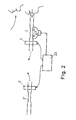
- FIG. 2 illustrates the diagram of the air sample intake system.
- a Poiseuille tube was used to automatically open the solenoid valves.
- the pressure variation it creates when the fluid passes is converted into an electrical signal by a pressure transducer.
- the signal is shaped by an amplifier which, via an interface, controls the simultaneous opening of the solenoid valves, 3 and 3 '.
- the 5 and 5 'cascade impactors operate at a nominal flow rate strictly defined by the manufacturer, a flow rate which also guarantees the particle size analysis of the aerosols.
- Bell spirometers are the necessary buffer between the intermittent flow of exhalations and the regular flow of impactors. They also serve as a benchmark for adjusting the average flow rate directed towards the impactors.
- the maximum volume displacement of the bells is 6,580 cm 3 .
- the cap of the bells consists of bidistilled water 22.
- the bottom of the spirometers is removable; it is on it that the tips of the air supply and evacuation 17 and 12 and the adjustment of the average flow rate metering devices are connected. At the bottom is fixed the hygrometric probe holder which allows to measure the hygrometric degree in the spirometer at the beginning and at the end of the experiment.
- a humidifier 6 is connected to a flow distributor 13 with six doors, connected sequentially to a micrometric valve 14, a flow meter 15 and a bottle of compressed air 7. These six doors are connected to six orifices 12 distributed three to three in the two spirometers. This dilution air is not only used to continuously humidify ( ⁇ 33 cm 3 / s or - 2 I / min) the air contained in the spirometric section but also serves as a backup in the event of too low expiration volume. The excess air is expelled through the remaining (3 x2) six orifices 17 and is regulated by a second flow distributor 18, a micrometric valve 19, a flow meter 20 and a vacuum pump P 3 .
- the final filters collect aerosols of less than 0.25 ⁇ m and 0.50 ⁇ m, respectively.
- the impaction surfaces 24 have been covered with a millipore membrane which receives the aerosols to be analyzed and the final filters 25 are millipore membranes with a 0.4 ⁇ m porosity.
- the pressure drop downstream of the impactors is ensured by a dry rotary pump: P 1 and P 2 .
- Each impactor is connected to the spirometer by a stainless steel tube, the diameter of which is calculated so as to equalize the air speed inside the two tubes and thus guarantee similar aerosol behavior.
- the impactors ensure aerosol fractionation according to their aerodynamic diameter, which allows us to directly compare our results with the TASK LUNG GROUP model which provides the deposition data as a function of the average aerodynamic diameter of aerosols for a normal log particle size distribution. given (cf. Healta Physics, Pergamon Press 1966, Vol. 12, pages 173-207).
- the whole system is enclosed in a double-walled chamber 10 and insulated with glass wool. Thermostatization is ensured by a hot air blower connected to a thermostat, the sensor element of which is a thermocouple.
- a fan pulses the hot air through a tube attached to three walls of the chamber.
- This tube is provided with a multitude of holes which send the hot air horizontally and vertically, which ensures uniform air conditioning of the chamber.
- the thermocouple is fixed in the center of the chamber; it is connected to a relay thermostat which controls the fan (220 VA).
- Three thermometric probes are fixed in different places in order to check the homogeneity. of the temperature of the bedroom. Each thermometric probe is connected to a digital temperature indicator fitted with a communication unit intended for the selection of 6 thermometric probes and two hygrometric probes (used in spirometers).
- the impactors will be thermostatically controlled according to the same principle.
- the heating system has been simplified: a rheostat regulated the intensity of the current passing through the heating strips wound around the impactors.
- the temperature of the impactors is maintained at a value of 40 ° C so as to avoid condensation of the water vapor following the adiabatic expansion which occurs in the nozzles of the device.
- the determination of the metals deposited on the impaction surfaces can be carried out by numerous analytical techniques provided that they are sufficiently sensitive: polarography, colorimetry, atomic absorption spectrometry or analyzes by nuclear activation (thermal neutrons, protons) or by activation. electron with charged particles (proton induced x Ray emission).
Landscapes
- Health & Medical Sciences (AREA)
- Life Sciences & Earth Sciences (AREA)
- General Health & Medical Sciences (AREA)
- Pulmonology (AREA)
- Physics & Mathematics (AREA)
- Molecular Biology (AREA)
- Pathology (AREA)
- Engineering & Computer Science (AREA)
- Biomedical Technology (AREA)
- Medical Informatics (AREA)
- Veterinary Medicine (AREA)
- Biophysics (AREA)
- Surgery (AREA)
- Animal Behavior & Ethology (AREA)
- Physiology (AREA)
- Public Health (AREA)
- Heart & Thoracic Surgery (AREA)
- Chemical & Material Sciences (AREA)
- Analytical Chemistry (AREA)
- Biochemistry (AREA)
- General Physics & Mathematics (AREA)
- Immunology (AREA)
- Sampling And Sample Adjustment (AREA)
Description
- L'objet de la présente invention est la réalisation d'un appareil pour le prélèvement et l'analyse des aérosols atmosphériques.
- Lorsque l'on veut réaliser un système de récolte des aérosols expirés, on se trouve confronté à de nombreux problèmes dus aux réactions physiques et chimiques subies par les aérosols durant leur trajet entre le site de prélèvement et le système de piégeage. Il faut limiter au mieux les pertes sur les parois de l'instrument et les changements de distribution granulométrique qui peuvent conduire à des erreurs systématiques sur l'interprétation du taux de déposition en fonction du diamètre des particules. Les différences que l'on trouve dans la littérature ne sont pas imputables seulement aux différences physiologiques et pathologiques de sujet à sujet mais également à la méthodologie utilisée (génération d'aérosols, types d'aérosols, préleveurs, ...).
- Nous proposons ici un système de prélèvement qui, en principe, doit faire subir aux échantillons d'air inhalés et aux échantillons exhalés le même traitement physique, ce qui, bien entendu, est la seule condition qui permette une comparaison objective des deux échantillons et donc une mesure exacte des taux de déposition dans les voies respiratoires.
- Avant de décrire notre propre système de prélèvement, il serait intéressant, par comparaison, de présenter les principes qui guident les autres techniques d'investigation. Les premières recherches ont été basées sur l'étude de l'absorption par les voies respiratoires d'aérosols monodimension- nels créés par des générateurs. Il s'agit là bien sûr d'une technique artificielle qui ne reproduit certainement pas la réalité des particules aériennes, avec leurs propriétés et hygroscopicité, par exemple. G. DESAEDELEER, le premier, a imaginé de prélever des particules aériennes inhalées et exhalées grâce à deux impacteurs, préleveurs capables d'isoler les particules suivant différentes fractions granulométriques. Un appareil conforme au préambule de la revendication jointe a été décrit par cet auteur dans l'article Environmental Science and Technology 9, 1975, p. 971-972. D'autres chercheurs ont appliqué ce même principe mais sans veiller particulièrement à une stricte similitude des deux chaînes de prélèvement: la chaîne de prélèvement de l'air inhalé (ambiant) et la chaîne de prélèvement de l'air expiré. (cf. en particulier Akselsson et al, Ann. Occup. Hyg. 19, 1976, p. 225-238 et Annegarn et al, in Session of «Particulate Analysis and Sampling», American Institute of Chemical Engineer 86th National Meeting, Houston, Texas, April 1-5,1979.
- Le système mis au point est destiné à collecter des aérosols atmosphériques, donc non produits par des générateurs. Deux chaînes de prélèvement assurent, grâce des impacteurs, l'analyse granulométrique des aérosols ambiants et expirés. En:: fin, une similitude rigoureuse a été prévue dans les deux chaînes de manière à assurer les conditions identiques de prélèvement des deux échantillons d'aérosol: en particulier, on a veillé:
- - à réduire au minimum les perturbations subies par les flux d'air échantillonné (coudes, constrictions, clapets, ...),
- - à assurer une même température et une même hygroscopicité (saturation à 34 °C) des deux échantillons d'air,
- - à assurer une parfaite symétrie des deux chaînes (débits, volumes, flux, géométrie, ...).
- Les conduits d'air sont en métal de manière à supprimer tout effet électrostatique sur les particules aériennes.
- La figure 1 montre le schéma général de l'appareil et la figure 2, le système d'admission des échantillons d'air; la figure 3 se réfère à la régulation des débits d'air et la figure 4 montre les impacteurs en série.
- La figure 1 reprend le schéma général du système; le reste de la description détaillera les diverses sections de l'appareil qui est de conception tout à fait symétrique.
- Chacune des deux chaînes de prélèvement est constituée (dans l'ordre du passage des échantillons d'air. Les mêmes éléments des deux chaînes ont le même numéro de référence),
- - d'une section d'admission de l'air avec un embout respiratoire 1 et un embout à l'air libre, l'un tube de Poiseuille 2-2' qui commande l'ouverture ou la fermeture d'une électrovanne, 3-3',
- - d'une section spirométrique (à cloche) 4-4' qui régularise le débit de l'air admis dans les impacteurs 5-5',
- - de deux impacteurs travaillant en parallèle et destinés à prélever les particules suivant deux classes granulométriques (de 0,25 µm à 4 µm et de 0.50 µm à 16 gm),
- - un humidificateur 6 porte l'humudité relative de l'air à la valeur imposée par le système respiratoire humain (saturation à 34 °C),
- - un système d'admission d'air excédentaire alimenté par une bouteille d'air 7 comprimé fournit l'appoint d'air nécessaire pour garantir le débit nominal des impacteurs (208+17,5=225 cm3/s ou 12,5+1,05=13,5/1 min) au cas où le rythme respiratoire du sujet est insuffisant;
- - au contraire, en cas d'expiration à rythme rapide, une pompe P3 assure l'expulsion de l'air excédentaire: excès ou déficit d'air sont compensés par un jeu de vannes micrométriques commandées manuellement.
- Les deux chaînes de prélèvement, symétriques par leur structure fonctionnent aussi de manière strictement synchrone:
- - électrovannes asservies au même système de commande,
- - spiromètres accouplés,
- - débits strictement comparables, ...
- Lorsque le sujet exhale son volume d'air dans le système l'électrovanne à tiroir 3 s'ouvre automatiquement et l'air est pulsé dans le réservoir 4 d'où les particules sont prélevées par deux impacteurs à cascades 5 de type connu. La partie supérieure du spiromètre 4 s'élevant sous la pression causée par l'expiration du sujet entraîne, par un système de contrepoids CP 9 le second spiromètre 4' dans son mouvement ascendant. L'ouverture de 3 ayant entraîné électriquement l'ouverture de 3', la dépression causée dans la chaîne «Atmosphère» par le mouvement de la cloche pulse dans le réservoir 4' une quantité d'air égale à l'air exhalé par le sujet.
- Les deux chaînes sont placées dans une enceinte 10 maintenue à une température supérieure à 35 °C afin d'éviter les pertes par condensation suivie de déposition sur les parois.
- La chambre d'inhalation ainsi construite permet d'assurer au mieux un parallélisme rigoureux du comportement des particules dans les deux chaînes de prélèvement.
- Afin d'éviter toute perturbation du flux d'air prélevé par l'appareil, on a renoncé à l'emploi de la valve à trois voies qui fait classiquement suite à l'embout bucal des chambres d'inhalation. On a donc opté pour un procédé plus exigeant pour le sujet soumis à l'examen mais plus fiable du point de vue récolte des aérosols. Une valve à trois voies eût permis au suject examiné d'inspirer et d'expirer l'air sans quitter l'embout bucal, ce qui est manifestement la solution la plus facile. Malheureusement, la valve à trois voies constitue un piège à particules incompatible avec les exigences imposées pour le fonctionnement de l'appareil; en outre, une telle vanne impose une pulsion en amont, elle ne peut donc être utilisée à l'entrée de la chaîne qui prélève l'air ambiant. Son emploi dans la chaîne d'expiration eût donc compromis le parallélisme strict entre les deux chaînes, qui est le but de l'invention.
- On a préféré adopter un système actif qui impose au sujet d'inhalter l'air ambiant à bouche libre et d'insuffler l'air expiré à travers une électrovanne commandée par un senseur de flux. Outre qu'un système actif de ce genre perturbe bien moins l'écoulement de l'air, il permet également, par asservissement parallèle d'assurer simultanément la prise d'échantillon d'air ambiant par la deuxième chaîne. La figure 2 illustre le schéma du système d'admission des échantillons d'air.
- Pour ouvrir automatiquement les électrovannes, on a utilisé un tube de Poiseuille. La variation de pression qu'il crée au passage du fluide est convertie en un signal électrique par un transducteur de pression. Le signal est mis en forme par un amplificateur qui, par l'intermédiaire d'une interface, commande l'ouverture simultanée des électrovannes, 3 et 3'.
- Les impacteurs à cascade 5 et 5' fonctionnent sous un débit nominal strictement défini par le constructeur, débit qui garantit d'ailleurs l'analyse granulométrique des aérosols. Les spiromètres à cloche constituent le tampon nécessaire entre le débit intermittent des expirations et le débit régulier des impacteurs. Ils servent également de repère au réglage du débit moyen dirigé vers les impacteurs.
- Le déplacement volumique maximum des cloches est de 6 580 cm3. Le bouchon des cloches est constitué d'eau bidistillée 22. Le fond des spiromètres est amovible; c'est sur lui que viennent se connecter les embouts de l'adduction et d'évacuation de l'air 17 et 12 et du réglage des doseurs de débits moyens. En bas se fixe le porte-sonde hygrométrique qui permet de mesurer le degré hygrométrique dans le spiromètre en début et en fin d'expérience.
- Le schéma reporté à la figure 3 illustre la régulation des débits d'air.
- Un humidificateur 6 est relié à un répartiteur de flux 13 à six portes, connecté séquentiellement à une vanne micrométrique 14, un fluxmètre 15 et une bouteille d'air comprimé 7. Ces six portes sont reliées à six orifices 12 répartis trois à trois dans les deux spiromètres. Cet air de dilution sert non seulement à humidifier en continu (~ 33 cm3/s ou - 2 I/min) l'air contenu dans le section spirométrique mais aussi sert d'appoint en cas de volume d'expiration trop faible. L'expulsion d'air excédentaire s'effectue par les (3 x2) six orifices 17 restants et est réglée par un deuxième répartiteur de flux 18, une valve micrométrique 19, un fluxmètre 20 et une pompe à vide P3.
- Chaque spiromètre est relié à deux impacteurs (fig. 4) à cascade fe flux égal à (17,5 cm3/s et 208 cm3/s (1,05 I/min et 12,5 I/min) et dont les diamètres de coupure (= diamètre aérodynamique des particules dont l'efficience d'impaction est de 50%) sont égaux à > 4, 2,1, 0.5, 0.25 et > 16,8,4,2,1,0.5 µm respectivement. Les filtres finals recueillent respectivement les aérosols inférieurs à 0.25 µm et à 0.50 um.
- Les surfaces d'impaction 24 ont été recouvertes d'une membrane millipore qui reçoit les aérosols à analyser et les filtres finals 25 sont des membranes millipore de 0.4 µm de porosité. La chute de pression en aval des impacteurs est assurée par une pompe rotative à sec: P1 et P2. Chaque impacteur est relié au spiromètre par un tube d'Inox dont le diamètre est calculé de façon à égaliser la vitesse de l'air à l'intérieur des deux tubes et d'y garantir ainsi un comportement analogue des aérosols. Les impacteurs assurent un fractionnement des aérosols en fonction de leur diamètre aérodynamique, ce qui permet de confronter directement nos résultats avec le modèle du TASK LUNG GROUP qui fournit les données de déposition en fonction du diamètre aérodynamique moyen d'aérosols pour une distribution granulométrique log normale donnée (cf. Healta Physics, Perga- mon Press 1966, Vol. 12, pages 173-207).
- L'ensemble du système est enfermé dans une chambre 10 à double parois et isolée avec de la laine de verre. La thermostatisation est assurée par un pulseur d'air chaud connecté à un thermostat dont l'élément senseur est un thermocouple.
- Un ventilateur pulse l'air chaud dans un tube fixé à trois parois de la chambre. Ce tube est muni d'une multitude de trous qui envoient l'air chaud horizontalement et verticalement, ce qui assure une climatisation uniforme de la chambre. Le thermocouple est fixé au centre de la chambre; il est relié à un thermostat à relais qui commande de ventilateur (220 V.A.). Trois sondes thermométriques sont fixées à des endroits différents afin de contrôler l'homogénéité. de la température de la chambre. Chaque sonde thermométrique est reliée à un indicateur numérique de température muni d'une unité de communication prévu pour la sélection de 6 sondes thermométriques et de deux sondes hygrométriques (utilisées dans les spiromètres).
- Il est normalement prévu que les impacteurs soient thermostatisés suivant le même principe. Cependant, pour des raisons de commodité, le système de chauffage a été simplifié: un rhéostat réglait l'intensité du courant traversant des bandes chauffantes enroulées autour des impacteurs. La température des impacteurs est maintenue à une valeur de 40 °C de manière à éviter la condensation de la vapeur d'eau suite à la détente adiabatique qui se produit dans les tuyères de l'appareil.
- Le dosage des métaux déposés sur les surfaces d'impaction peut se réaliser par de nombreuses techniques analytiques pourvu qu'elles soient suffisamment sensibles: polarographie, colorimétrie, spectrométrie d'absorption atomique ou analyses par activation nucléaire (neutrons thermiques, protons) ou par activation électronique aux particules chargées (proton induced x Ray emission).
Claims (1)
Applications Claiming Priority (2)
| Application Number | Priority Date | Filing Date | Title |
|---|---|---|---|
| LU83254 | 1981-03-25 | ||
| LU83254 | 1981-03-25 |
Publications (2)
| Publication Number | Publication Date |
|---|---|
| EP0061074A1 EP0061074A1 (fr) | 1982-09-29 |
| EP0061074B1 true EP0061074B1 (fr) | 1985-07-03 |
Family
ID=19729615
Family Applications (1)
| Application Number | Title | Priority Date | Filing Date |
|---|---|---|---|
| EP82101928A Expired EP0061074B1 (fr) | 1981-03-25 | 1982-03-11 | Appareil pour le prélèvement et l'analyse des aérosols atmosphériques absorbés par les êtres vivants |
Country Status (2)
| Country | Link |
|---|---|
| EP (1) | EP0061074B1 (fr) |
| DE (1) | DE3264494D1 (fr) |
Families Citing this family (9)
| Publication number | Priority date | Publication date | Assignee | Title |
|---|---|---|---|---|
| IL117775A (en) * | 1995-04-25 | 1998-10-30 | Ebara Germany Gmbh | Inhalation system with gas exhaust cleaner and operating process for it |
| DE19515145C1 (de) * | 1995-04-25 | 1996-11-07 | Ebara Germany Gmbh | Evakuierungssystem mit Abgasreinigung und Betriebsverfahren hierfür |
| US7364553B2 (en) | 2002-12-20 | 2008-04-29 | Amidex, Inc. | Breath aerosol management and collection system |
| US7073402B2 (en) * | 2003-08-12 | 2006-07-11 | Skc, Inc. | Air sampler with parallel impactors |
| US9791353B2 (en) * | 2008-08-29 | 2017-10-17 | Research International, Inc. | Concentrator |
| CN107115112B (zh) * | 2016-02-24 | 2023-04-14 | 兰州大学第一医院 | 一种可定量监测的吸气、呼气功能锻炼装置 |
| CN108146628A (zh) * | 2017-12-18 | 2018-06-12 | 佛山市神风航空科技有限公司 | 搭载气溶胶采样装置的无人机 |
| CN112816375A (zh) * | 2020-12-29 | 2021-05-18 | 上海工物高技术产业发展有限公司 | 气溶胶监测装置 |
| CN120521918B (zh) * | 2025-07-28 | 2025-09-19 | 山东省地质矿产勘查开发局第三地质大队(山东省第三地质矿产勘查院、山东省海洋地质勘查院) | 一种水文地质监测用的取样勘察装置 |
Family Cites Families (5)
| Publication number | Priority date | Publication date | Assignee | Title |
|---|---|---|---|---|
| DE1039702B (de) * | 1954-04-29 | 1958-09-25 | Erich Jaeger Fa | Spirograph mit zwei Spirometern |
| FR1147482A (fr) * | 1956-02-13 | 1957-11-26 | Spirographe enregistrant en modulation de fréquence | |
| DE1598068C3 (de) * | 1965-08-17 | 1978-11-09 | Fried. Krupp Gmbh, 4300 Essen | Vorrichtung zur selbsttätigen fortlaufenden Probenahme von Abgasen |
| NL7806340A (nl) * | 1978-06-12 | 1979-12-14 | Hoogstraat Med Tech | Werkwijze en inrichting voor het bepalen van een water- stofgehalte in een gas. |
| DE2938856A1 (de) * | 1979-09-26 | 1981-04-16 | Gesellschaft für Strahlen- und Umweltforschung mbH, 8000 München | Verfahren und vorrichtung zur ermittlung der ablagerung von partikeln im atemtrakt und/oder zur ueberpruefung der funktion des atemtraktes |
-
1982
- 1982-03-11 EP EP82101928A patent/EP0061074B1/fr not_active Expired
- 1982-03-11 DE DE8282101928T patent/DE3264494D1/de not_active Expired
Non-Patent Citations (2)
| Title |
|---|
| Environmental Science and Technology, 9, 1975, P. 971-972; G. Desaedeleer * |
| Health Physics, Pergamon Press, 1966, Vol. 12, p. 173-207 * |
Also Published As
| Publication number | Publication date |
|---|---|
| EP0061074A1 (fr) | 1982-09-29 |
| DE3264494D1 (en) | 1985-08-08 |
Similar Documents
| Publication | Publication Date | Title |
|---|---|---|
| US10888249B2 (en) | Cannabis drug detection device | |
| US10849361B2 (en) | Airflow puff topography measurement device and method | |
| Teague et al. | Sidestream cigarette smoke generation and exposure system for environmental tobacco smoke studies | |
| US8903474B2 (en) | Analysis of gases | |
| US10359417B2 (en) | Portable sampling device and method for detection of biomarkers in exhaled breath | |
| DE2816499C2 (de) | Verfahren und Anordnung zur Erkennung und Abtrennung des Alveolarluftanteiles aus der Atemluft | |
| MX2013010242A (es) | Un dispositivo portátil para tomar muestras y un método para tomar muestras de sustancias farmacéuticas a partir del aire exhalado. | |
| CN101788447B (zh) | 卷烟烟气气溶胶实时测试系统 | |
| EP0061074B1 (fr) | Appareil pour le prélèvement et l'analyse des aérosols atmosphériques absorbés par les êtres vivants | |
| CN102967541B (zh) | 适用于高温气体管道内颗粒物在线检测的装置及方法 | |
| EP3177923A1 (fr) | Système d'échantillonnage d'alcool respiratoire inviolable amovible | |
| WO2008060165A9 (fr) | Amélioration de procédés et d'appareils de recueil d'air expiré ou en rapport avec ceux-ci | |
| CN110226931A (zh) | 一种呼气分析装置及使用方法 | |
| WO2021028928A1 (fr) | Système et procédé pour déterminer le début et la progression d'une maladie | |
| CN115060554A (zh) | 卷烟侧流烟气成分捕集系统及捕集处理方法 | |
| CN219205966U (zh) | 一种气溶胶发生及采集装置 | |
| CN201917506U (zh) | 一种卷烟烟气气溶胶测试装置 | |
| CN212207388U (zh) | 一种能够缓冲末潮呼气的呼气进样器及呼气分析仪 | |
| CN103293547B (zh) | 便携式仿生α内污染剂量监测装置 | |
| CN115598295A (zh) | 电子烟烟气动物口鼻暴露时均一性和稳定性的检测方法 | |
| Liu et al. | Advances in particle sampling and measurement | |
| CN109557254B (zh) | 一种建立标准化卷烟烟气小鼠口鼻暴露方法的方法 | |
| WO2016166623A1 (fr) | Dispositif de détection de cannabis | |
| CN115427782A (zh) | 用于确定气溶胶的与源相关的颗粒尺寸分布的方法和气溶胶测量仪 | |
| CN114533037B (zh) | 一种基于儿童呼吸气体的疾病检测系统及方法 |
Legal Events
| Date | Code | Title | Description |
|---|---|---|---|
| PUAI | Public reference made under article 153(3) epc to a published international application that has entered the european phase |
Free format text: ORIGINAL CODE: 0009012 |
|
| AK | Designated contracting states |
Designated state(s): DE FR GB IT NL |
|
| 17P | Request for examination filed |
Effective date: 19821220 |
|
| ITF | It: translation for a ep patent filed | ||
| GRAA | (expected) grant |
Free format text: ORIGINAL CODE: 0009210 |
|
| AK | Designated contracting states |
Designated state(s): DE FR GB IT NL |
|
| REF | Corresponds to: |
Ref document number: 3264494 Country of ref document: DE Date of ref document: 19850808 |
|
| PLBE | No opposition filed within time limit |
Free format text: ORIGINAL CODE: 0009261 |
|
| STAA | Information on the status of an ep patent application or granted ep patent |
Free format text: STATUS: NO OPPOSITION FILED WITHIN TIME LIMIT |
|
| 26N | No opposition filed | ||
| PGFP | Annual fee paid to national office [announced via postgrant information from national office to epo] |
Ref country code: NL Payment date: 19870331 Year of fee payment: 6 |
|
| PG25 | Lapsed in a contracting state [announced via postgrant information from national office to epo] |
Ref country code: NL Effective date: 19881001 |
|
| NLV4 | Nl: lapsed or anulled due to non-payment of the annual fee | ||
| PG25 | Lapsed in a contracting state [announced via postgrant information from national office to epo] |
Ref country code: GB Free format text: LAPSE BECAUSE OF NON-PAYMENT OF DUE FEES Effective date: 19881121 |
|
| GBPC | Gb: european patent ceased through non-payment of renewal fee | ||
| PG25 | Lapsed in a contracting state [announced via postgrant information from national office to epo] |
Ref country code: FR Free format text: LAPSE BECAUSE OF NON-PAYMENT OF DUE FEES Effective date: 19881130 |
|
| PG25 | Lapsed in a contracting state [announced via postgrant information from national office to epo] |
Ref country code: DE Effective date: 19881201 |
|
| REG | Reference to a national code |
Ref country code: FR Ref legal event code: ST |