EP0061381A1 - Erzeuger von überhitztem Dampf - Google Patents
Erzeuger von überhitztem Dampf Download PDFInfo
- Publication number
- EP0061381A1 EP0061381A1 EP82400402A EP82400402A EP0061381A1 EP 0061381 A1 EP0061381 A1 EP 0061381A1 EP 82400402 A EP82400402 A EP 82400402A EP 82400402 A EP82400402 A EP 82400402A EP 0061381 A1 EP0061381 A1 EP 0061381A1
- Authority
- EP
- European Patent Office
- Prior art keywords
- outlet chamber
- chamber
- steam generator
- superheated steam
- steam
- Prior art date
- Legal status (The legal status is an assumption and is not a legal conclusion. Google has not performed a legal analysis and makes no representation as to the accuracy of the status listed.)
- Granted
Links
- XLYOFNOQVPJJNP-UHFFFAOYSA-N water Substances O XLYOFNOQVPJJNP-UHFFFAOYSA-N 0.000 claims abstract description 8
- 239000012530 fluid Substances 0.000 claims abstract description 4
- 238000007599 discharging Methods 0.000 claims description 4
- 238000005242 forging Methods 0.000 abstract description 2
- 238000001816 cooling Methods 0.000 abstract 1
- 238000010438 heat treatment Methods 0.000 abstract 1
- 230000008646 thermal stress Effects 0.000 description 4
- 230000001052 transient effect Effects 0.000 description 3
- DGAQECJNVWCQMB-PUAWFVPOSA-M Ilexoside XXIX Chemical compound C[C@@H]1CC[C@@]2(CC[C@@]3(C(=CC[C@H]4[C@]3(CC[C@@H]5[C@@]4(CC[C@@H](C5(C)C)OS(=O)(=O)[O-])C)C)[C@@H]2[C@]1(C)O)C)C(=O)O[C@H]6[C@@H]([C@H]([C@@H]([C@H](O6)CO)O)O)O.[Na+] DGAQECJNVWCQMB-PUAWFVPOSA-M 0.000 description 2
- 239000011324 bead Substances 0.000 description 2
- 239000007788 liquid Substances 0.000 description 2
- 229910052708 sodium Inorganic materials 0.000 description 2
- 239000011734 sodium Substances 0.000 description 2
- 230000007423 decrease Effects 0.000 description 1
- 238000007689 inspection Methods 0.000 description 1
- 238000009434 installation Methods 0.000 description 1
- 238000004519 manufacturing process Methods 0.000 description 1
- 230000002093 peripheral effect Effects 0.000 description 1
Images

Classifications
-
- F—MECHANICAL ENGINEERING; LIGHTING; HEATING; WEAPONS; BLASTING
- F22—STEAM GENERATION
- F22B—METHODS OF STEAM GENERATION; STEAM BOILERS
- F22B37/00—Component parts or details of steam boilers
- F22B37/02—Component parts or details of steam boilers applicable to more than one kind or type of steam boiler
- F22B37/22—Drums; Headers; Accessories therefor
-
- F—MECHANICAL ENGINEERING; LIGHTING; HEATING; WEAPONS; BLASTING
- F28—HEAT EXCHANGE IN GENERAL
- F28D—HEAT-EXCHANGE APPARATUS, NOT PROVIDED FOR IN ANOTHER SUBCLASS, IN WHICH THE HEAT-EXCHANGE MEDIA DO NOT COME INTO DIRECT CONTACT
- F28D7/00—Heat-exchange apparatus having stationary tubular conduit assemblies for both heat-exchange media, the media being in contact with different sides of a conduit wall
- F28D7/0066—Multi-circuit heat-exchangers, e.g. integrating different heat exchange sections in the same unit or heat-exchangers for more than two fluids
- F28D7/0075—Multi-circuit heat-exchangers, e.g. integrating different heat exchange sections in the same unit or heat-exchangers for more than two fluids with particular circuits for the same heat exchange medium, e.g. with the same heat exchange medium flowing through sections having different heat exchange capacities or for heating or cooling the same heat exchange medium at different temperatures
-
- F—MECHANICAL ENGINEERING; LIGHTING; HEATING; WEAPONS; BLASTING
- F28—HEAT EXCHANGE IN GENERAL
- F28F—DETAILS OF HEAT-EXCHANGE AND HEAT-TRANSFER APPARATUS, OF GENERAL APPLICATION
- F28F9/00—Casings; Header boxes; Auxiliary supports for elements; Auxiliary members within casings
- F28F9/02—Header boxes; End plates
-
- Y—GENERAL TAGGING OF NEW TECHNOLOGICAL DEVELOPMENTS; GENERAL TAGGING OF CROSS-SECTIONAL TECHNOLOGIES SPANNING OVER SEVERAL SECTIONS OF THE IPC; TECHNICAL SUBJECTS COVERED BY FORMER USPC CROSS-REFERENCE ART COLLECTIONS [XRACs] AND DIGESTS
- Y10—TECHNICAL SUBJECTS COVERED BY FORMER USPC
- Y10S—TECHNICAL SUBJECTS COVERED BY FORMER USPC CROSS-REFERENCE ART COLLECTIONS [XRACs] AND DIGESTS
- Y10S165/00—Heat exchange
- Y10S165/051—Heat exchange having expansion and contraction relieving or absorbing means
Definitions
- the present invention relates to a superheated steam generator comprising an outer shell having at its opposite ends a water inlet chamber to vaporize and overheat and a steam outlet chamber and a bundle of tubes connecting said chambers and in which circulates l water to vaporize and overheat by heat exchange with a hotter fluid circulating against the current around the tubes inside the outer shell.
- Such steam outlet chambers are traversed by superheated steam at very high temperature and under very high pressure. They include a steam outlet base and one or more inspection holes.
- the tube plate and the bottom, which constitute their walls, must be very thick. This results in the appearance of very significant thermal stresses during transient operating modes, when switching on, off or at change of regime. These constraints appear in the walls of the chamber, due to the delay with which the external wall of the chamber follows the variations of internal wall temperature. They also appear on the periphery of the tube plate, due to the difference in thermal inertia between the perforated zone of the plate and the full peripheral zone.
- the object of the present invention is to remedy these drawbacks and to reduce the thermal stresses on the external wall and on the tube plate surrounding the steam outlet chamber of the generator, and to avoid unacceptable damage during transient conditions. , while facilitating the manufacture of the steam generator.
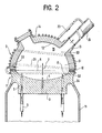
- the superheated steam generator according to the invention is characterized in that the steam outlet chamber has an external wall surrounded by a coil which communicates with said outlet chamber, so that part of the superheated steam admitted to the outlet chamber circulates in the coil.
- the coil opens into a pipe for discharging the superheated steam from the outlet chamber.
- the superheated steam generator comprises an external cylindrical shell 11 defining a vertical axis.
- This ferrule comprises at its lower end an inlet chamber 15 'of water to be vaporized supplied by a pipe 24' and, at its upper end, an outlet chamber 15 of superheated steam which communicates with an outlet pipe 24.
- the chambers 15 and 15 ' are connected by a bundle of vertical straight tubes 6 which are respectively connected to the inlet chamber 15' by a very thick tube plate 3 'and to the outlet chamber 15 by a tube plate 3 very thick.
- the water to be vaporized and superheated circulates from bottom to top in the tubes 6 of the steam generator, where it is vaporized and superheated by heat exchange with a hotter fluid which circulates from top to bottom around the tubes and at l 'Inside the shell 11, between an inlet pipe 16 and an outlet pipe 16'.
- the outlet chamber 15 has an external wall in two parts 8 and 2.
- the part 8 constitutes an annular zone forged in one piece 1 with the tube plate 3, the latter having a concave surface 4 on the side of the chamber 15.
- the part 1 is crossed by orifices such as 5 extending the tubes 6 of the bundle.
- the arrow 7 indicates the direction of circulation of the steam at the outlet of these orifices.
- the annular connection zone 8 is connected on its periphery with the second part 2 of the wall of the chamber by a weld bead 10, at the level of the reference plane 9 perpendicular to the axis of the ferrule 11.
- Part 1 is also connected by the annular zone 8 to the outer shell 11 of the generator.
- the second part 2 of the wall of the chamber 15, of hemispherical shape, with internal surface 12, is provided with a base 13 for connection to the steam evacuation pipe 24 and a manhole pipe 14 (other manholes can possibly be added).
- the steam outlet chamber 15 is surrounded by a coil 21, supplied with superheated steam by an orifice 22 pierced in its wall, and connected by a tube 23 to the pipe 24 for discharging the superheated steam .
- This coil cools or heats the wall external, depending on whether the temperature of the steam entering the steam outlet chamber decreases or increases, depending on variations in the operation of the steam generator.
- the invention is particularly applicable in generators of superheated steam by heat exchange with liquid sodium in power plants from a breeder nuclear reactor.
Landscapes
- Engineering & Computer Science (AREA)
- Physics & Mathematics (AREA)
- Thermal Sciences (AREA)
- Mechanical Engineering (AREA)
- General Engineering & Computer Science (AREA)
- Heat-Exchange Devices With Radiators And Conduit Assemblies (AREA)
- Heat Treatment Of Water, Waste Water Or Sewage (AREA)
- Vaporization, Distillation, Condensation, Sublimation, And Cold Traps (AREA)
Applications Claiming Priority (2)
| Application Number | Priority Date | Filing Date | Title |
|---|---|---|---|
| FR8105643 | 1981-03-20 | ||
| FR8105643A FR2502296A1 (fr) | 1981-03-20 | 1981-03-20 | Chambre de sortie de vapeur pour generateur de vapeur surchauffee |
Publications (2)
| Publication Number | Publication Date |
|---|---|
| EP0061381A1 true EP0061381A1 (de) | 1982-09-29 |
| EP0061381B1 EP0061381B1 (de) | 1983-12-28 |
Family
ID=9256481
Family Applications (1)
| Application Number | Title | Priority Date | Filing Date |
|---|---|---|---|
| EP82400402A Expired EP0061381B1 (de) | 1981-03-20 | 1982-03-08 | Erzeuger von überhitztem Dampf |
Country Status (6)
| Country | Link |
|---|---|
| US (1) | US4445568A (de) |
| EP (1) | EP0061381B1 (de) |
| JP (1) | JPS57169501A (de) |
| DE (1) | DE3260026D1 (de) |
| ES (1) | ES510587A0 (de) |
| FR (1) | FR2502296A1 (de) |
Families Citing this family (2)
| Publication number | Priority date | Publication date | Assignee | Title |
|---|---|---|---|---|
| DE102007040793A1 (de) * | 2007-08-28 | 2009-03-05 | Behr Gmbh & Co. Kg | Wärmetauscher |
| US9057516B2 (en) * | 2011-11-28 | 2015-06-16 | Trimeteor Oil and Gas Corporation | Superheated steam generators |
Citations (3)
| Publication number | Priority date | Publication date | Assignee | Title |
|---|---|---|---|---|
| CH359716A (fr) * | 1959-01-02 | 1962-01-31 | Huet Andre | Générateur de vapeur |
| FR2010568A1 (de) * | 1968-06-10 | 1970-02-20 | Westinghouse Electric Corp | |
| FR2386798A1 (fr) * | 1977-04-05 | 1978-11-03 | Commissariat Energie Atomique | Echangeur de chaleur pour hautes temperatures et hautes pressions |
Family Cites Families (6)
| Publication number | Priority date | Publication date | Assignee | Title |
|---|---|---|---|---|
| US466092A (en) * | 1891-12-29 | Heater | ||
| US2102424A (en) * | 1934-03-23 | 1937-12-14 | Gen Electric | Mercury power plant |
| GB800385A (en) * | 1955-12-20 | 1958-08-27 | Rolls Royce | Improvements in or relating to steam generators |
| US3596638A (en) * | 1968-10-15 | 1971-08-03 | Siemens Ag | Forced-flow steam generator to be heated by pressurized coolant of a nuclear reactor |
| US3930537A (en) * | 1974-05-06 | 1976-01-06 | The United States Of America As Represented By The United States Energy Research And Development Administration | Heat exchanger |
| US4235284A (en) * | 1976-12-16 | 1980-11-25 | The United States Of America As Represented By The United States Department Of Energy | Heat exchanger with auxiliary cooling system |
-
1981
- 1981-03-20 FR FR8105643A patent/FR2502296A1/fr active Granted
-
1982
- 1982-03-08 EP EP82400402A patent/EP0061381B1/de not_active Expired
- 1982-03-08 DE DE8282400402T patent/DE3260026D1/de not_active Expired
- 1982-03-15 US US06/358,181 patent/US4445568A/en not_active Expired - Fee Related
- 1982-03-18 ES ES510587A patent/ES510587A0/es active Granted
- 1982-03-19 JP JP57043019A patent/JPS57169501A/ja active Pending
Patent Citations (3)
| Publication number | Priority date | Publication date | Assignee | Title |
|---|---|---|---|---|
| CH359716A (fr) * | 1959-01-02 | 1962-01-31 | Huet Andre | Générateur de vapeur |
| FR2010568A1 (de) * | 1968-06-10 | 1970-02-20 | Westinghouse Electric Corp | |
| FR2386798A1 (fr) * | 1977-04-05 | 1978-11-03 | Commissariat Energie Atomique | Echangeur de chaleur pour hautes temperatures et hautes pressions |
Also Published As
| Publication number | Publication date |
|---|---|
| ES8401600A1 (es) | 1983-12-16 |
| FR2502296A1 (fr) | 1982-09-24 |
| DE3260026D1 (en) | 1984-02-02 |
| ES510587A0 (es) | 1983-12-16 |
| JPS57169501A (en) | 1982-10-19 |
| FR2502296B1 (de) | 1984-03-09 |
| US4445568A (en) | 1984-05-01 |
| EP0061381B1 (de) | 1983-12-28 |
Similar Documents
| Publication | Publication Date | Title |
|---|---|---|
| EP0688421B1 (de) | Wärmeaustauschvorrichtung und verfahren zur kühlung der aussenwand dieser vorrichtung | |
| FR2462680A1 (fr) | Chaudiere a recuperation de chaleur residuelle | |
| EP0246942B1 (de) | Rohrbündelwärmetauscher mit doppelwandigem Rohrboden | |
| FR3062235B1 (fr) | Reacteur nucleaire integrant un echangeur de chaleur primaire de securite | |
| EP0057643B1 (de) | Schutzeinrichtung für die Rohrplatte an der heissen Seite eines vertikaler Wärmetauschers | |
| EP0068913A1 (de) | Schneller Brüter mit Einrichtung zur Abführung von Restwärme | |
| EP0061381B1 (de) | Erzeuger von überhitztem Dampf | |
| EP0027094A1 (de) | Wasserkammern für Dampferzeuger | |
| FR2945106A1 (fr) | Element modulaire pour radiateur a fluide caloporteur et radiateur electrique constitue d'au moins un tel element | |
| EP0020265B1 (de) | Wärmeaustauscher für Kernreaktor | |
| FR2636125A1 (fr) | Generateur de fluide chaud, notamment d'eau chaude | |
| EP2251612A1 (de) | Elektrisches Heizgerät mit Wärmeübertragungsflüssigkeit, das aus gegossenen Modulelementen besteht | |
| FR2540971A1 (fr) | Generateur de vapeur pour un reacteur nucleaire refroidi par du metal liquide | |
| EP0775876B1 (de) | Meanderförmiger,kombinierter Wärmetauscher mit komplexer,gerader Strecke | |
| FR2482269A2 (fr) | Recepteur solaire perfectionne a haute temperature | |
| FR2858845A1 (fr) | Echangeur de chaleur et procede de fabrication | |
| EP0330542B1 (de) | Leistungsröhre mit einem Flüssigkeitskühlkreislauf | |
| EP0487434B1 (de) | Wärmetauscher für Gaskessel, Herstellungsverfahren dafür und Kessel mit einem solchen Wärmetauscher | |
| FR3020494A1 (fr) | Element combustible nucleaire | |
| EP0065912A1 (de) | Innenbehälter für Kernreaktoren mit schnellen Neutronen | |
| FR2518707A1 (fr) | Dispositif de production de vapeur par echange de chaleur entre un metal liquide caloporteur et de l'eau alimentaire | |
| EP1593925B1 (de) | Plattenwärmetauscher | |
| EP0036347B1 (de) | Zwischenwärmeaustauscher für Nuklear-Reaktor mit schnellen Neutronen | |
| WO1982001582A1 (fr) | Echangeur de chaleur pour chaudieres domestiques de chauffage central | |
| FR2492078A1 (fr) | Condenseur basse temperature de grande puissance |
Legal Events
| Date | Code | Title | Description |
|---|---|---|---|
| PUAI | Public reference made under article 153(3) epc to a published international application that has entered the european phase |
Free format text: ORIGINAL CODE: 0009012 |
|
| AK | Designated contracting states |
Designated state(s): BE CH DE GB IT NL |
|
| 17P | Request for examination filed |
Effective date: 19830205 |
|
| ITF | It: translation for a ep patent filed | ||
| GRAA | (expected) grant |
Free format text: ORIGINAL CODE: 0009210 |
|
| AK | Designated contracting states |
Designated state(s): BE CH DE GB IT LI NL |
|
| REF | Corresponds to: |
Ref document number: 3260026 Country of ref document: DE Date of ref document: 19840202 |
|
| PGFP | Annual fee paid to national office [announced via postgrant information from national office to epo] |
Ref country code: DE Payment date: 19840225 Year of fee payment: 3 |
|
| PGFP | Annual fee paid to national office [announced via postgrant information from national office to epo] |
Ref country code: CH Payment date: 19840305 Year of fee payment: 3 |
|
| PGFP | Annual fee paid to national office [announced via postgrant information from national office to epo] |
Ref country code: BE Payment date: 19840331 Year of fee payment: 3 |
|
| PLBE | No opposition filed within time limit |
Free format text: ORIGINAL CODE: 0009261 |
|
| STAA | Information on the status of an ep patent application or granted ep patent |
Free format text: STATUS: NO OPPOSITION FILED WITHIN TIME LIMIT |
|
| 26N | No opposition filed | ||
| PGFP | Annual fee paid to national office [announced via postgrant information from national office to epo] |
Ref country code: NL Payment date: 19870331 Year of fee payment: 6 |
|
| PG25 | Lapsed in a contracting state [announced via postgrant information from national office to epo] |
Ref country code: GB Effective date: 19890308 |
|
| PG25 | Lapsed in a contracting state [announced via postgrant information from national office to epo] |
Ref country code: LI Effective date: 19890331 Ref country code: CH Effective date: 19890331 Ref country code: BE Effective date: 19890331 |
|
| BERE | Be: lapsed |
Owner name: COMMISSARIAT A L'ENERGIE ATOMIQUE ETABLISSEMENT D Effective date: 19890331 |
|
| PG25 | Lapsed in a contracting state [announced via postgrant information from national office to epo] |
Ref country code: NL Effective date: 19891001 |
|
| GBPC | Gb: european patent ceased through non-payment of renewal fee | ||
| NLV4 | Nl: lapsed or anulled due to non-payment of the annual fee | ||
| REG | Reference to a national code |
Ref country code: CH Ref legal event code: PL |
|
| PG25 | Lapsed in a contracting state [announced via postgrant information from national office to epo] |
Ref country code: DE Effective date: 19891201 |