EP0061514B1 - Rayonnage à consoles - Google Patents
Rayonnage à consoles Download PDFInfo
- Publication number
- EP0061514B1 EP0061514B1 EP81107034A EP81107034A EP0061514B1 EP 0061514 B1 EP0061514 B1 EP 0061514B1 EP 81107034 A EP81107034 A EP 81107034A EP 81107034 A EP81107034 A EP 81107034A EP 0061514 B1 EP0061514 B1 EP 0061514B1
- Authority
- EP
- European Patent Office
- Prior art keywords
- cantilever
- uprights
- bracket
- profile
- footplate
- Prior art date
- Legal status (The legal status is an assumption and is not a legal conclusion. Google has not performed a legal analysis and makes no representation as to the accuracy of the status listed.)
- Expired
Links
Images

Classifications
-
- A—HUMAN NECESSITIES
- A47—FURNITURE; DOMESTIC ARTICLES OR APPLIANCES; COFFEE MILLS; SPICE MILLS; SUCTION CLEANERS IN GENERAL
- A47B—TABLES; DESKS; OFFICE FURNITURE; CABINETS; DRAWERS; GENERAL DETAILS OF FURNITURE
- A47B57/00—Cabinets, racks or shelf units, characterised by features for adjusting shelves or partitions
- A47B57/30—Cabinets, racks or shelf units, characterised by features for adjusting shelves or partitions with means for adjusting the height of detachable shelf supports
- A47B57/40—Cabinets, racks or shelf units, characterised by features for adjusting shelves or partitions with means for adjusting the height of detachable shelf supports consisting of hooks coacting with openings
- A47B57/42—Cabinets, racks or shelf units, characterised by features for adjusting shelves or partitions with means for adjusting the height of detachable shelf supports consisting of hooks coacting with openings the shelf supports being cantilever brackets
Definitions
- the invention relates to a cantilever rack for long goods products, such as boards, pipes, profiled iron and the like
- Cantilever-extending hooks are designed for releasable hanging in the punched-outs
- the stands are designed as T-profile stands and the punched-outs are arranged in pairs in the flanges of the T-profile stands at the same height one above the other.
- the cantilever arms which consist of double-T profiles, are provided at one end with a base plate, by means of which the cantilever arms are screwed onto stands made of double-T profiles.
- DE-U-77 11 112 shows a screwless adjustable heavy-duty cantilever rack, in which the cantilever arms made of punched and bent sheet metal are suspended from double-T stands. To secure the cantilever arms, side flaps are provided on the cantilever arms in addition to hooks that are punched out in the stands.
- the invention has for its object to provide a cantilever rack that is easy to assemble and disassemble and that can be easily adapted to the goods to be stored and the spatial conditions.
- the cantilever arms are designed as double-T profiles, that a foot plate is attached to the end of each cantilever arm, and that the two hooks are arranged on each foot plate as exclusive holding elements.
- the height of the foot plate can be greater than the height of the cantilever.
- the distance of the side of the hook against the inside of the flange from the side of the footplate against the outside of the flange can be substantially equal to the thickness dimension of the flange.
- the front of the base plate can be connected to the underside of the cantilever arm by means of a support triangle. These parts can also be welded together.
- support feet can be attached to the lower end of the profile stand.
- the mutual spacing of the profile stands is ensured in that spacers are arranged between the profile stands. These can be screwed on.
- Diagonal tension bandages can also be arranged between the profile stands.
- This cantilever rack can be extended in blocks as required.
- the cantilever rack according to the invention has T-profile stand 1.
- Two stands are provided for at least one shelf.
- the number of stands is arbitrary, and these T-profile stands can be arranged at the same or different intervals. In the illustrated embodiment, these T-profile stands are double T-profile stands.
- Pairs of cutouts 3 are arranged in the flanges 2 of this profile stand 1.
- the punched-out portions 3 of each pair are at the same height, and the pairs are arranged one above the other in the flanges 2.
- These punched-out pairs 3 can be formed in one flange 2 or in both flanges of the double-T beam. These cut-outs can either be square or round.
- the cantilever arms 4 have hooks 5 at one end, with which they can be detachably suspended in a pair of punched-outs 3 in the flanges 2 of the profile stand 1. It can be seen that any number of cantilever arms can be hung in a stand in a simple manner by this design, specifically at predetermined and desired heights, and that height changes of the cantilever arms can optionally be carried out in a very simple manner.
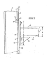
- the hooks 5 extend upwards relative to the upper side 6 of the cantilever arm 2. This makes hooking and unhooking the cantilever arms considerably easier.
- a foot plate 7 is attached to the end of the cantilever arm 2.
- This base plate 7 can be welded to the cantilever arm 4, for example.
- a good support of the cantilever on the profile stand 1 is achieved in that the height H of the foot plate 7 is greater than the height h of the cantilever 4.
- the structure is designed so that the Distance D of the side 9 of the hook 5 resting against the inside 8 of the flange 2 from the side 18 of the foot plate 7 resting against the outside 10 of the flange 2 is substantially equal to the thickness dimension d of the flange. This avoids a lot of tolerances could lead to an unstable structure.
- the front side 11 of the foot plate 7 is connected to the underside 12 of the cantilever arm 2 by means of a support triangle 13.
- a welded connection can also be provided here. In this way, the load transmission, in particular the transmission of moment loads, is improved.
- support feet 14 are fastened, the connection again being able to be made by means of welding.
- a screw connection is also possible. This embodiment is particularly advantageous when no fixed installation is intended.
- Spacers 15 can be arranged between the profile stands 1, and these spacers can be screwed on. If a fixed installation is provided, a welded connection can also be provided.
Landscapes
- Assembled Shelves (AREA)
- Rod-Shaped Construction Members (AREA)
- Cabinets, Racks, Or The Like Of Rigid Construction (AREA)
- Warehouses Or Storage Devices (AREA)
Claims (7)
Priority Applications (1)
| Application Number | Priority Date | Filing Date | Title |
|---|---|---|---|
| AT81107034T ATE20304T1 (de) | 1981-03-24 | 1981-09-07 | Kragarm-regal. |
Applications Claiming Priority (2)
| Application Number | Priority Date | Filing Date | Title |
|---|---|---|---|
| DE19818108652U DE8108652U1 (de) | 1981-03-24 | 1981-03-24 | Kragarm-regal, einhaengbare ausfuehrung |
| DE8108652U | 1981-03-24 |
Publications (2)
| Publication Number | Publication Date |
|---|---|
| EP0061514A1 EP0061514A1 (fr) | 1982-10-06 |
| EP0061514B1 true EP0061514B1 (fr) | 1986-06-11 |
Family
ID=6726023
Family Applications (1)
| Application Number | Title | Priority Date | Filing Date |
|---|---|---|---|
| EP81107034A Expired EP0061514B1 (fr) | 1981-03-24 | 1981-09-07 | Rayonnage à consoles |
Country Status (3)
| Country | Link |
|---|---|
| EP (1) | EP0061514B1 (fr) |
| AT (1) | ATE20304T1 (fr) |
| DE (1) | DE8108652U1 (fr) |
Cited By (6)
| Publication number | Priority date | Publication date | Assignee | Title |
|---|---|---|---|---|
| DE3832537A1 (de) * | 1988-09-24 | 1990-03-29 | Hoelscher Ottokar | Kragarm-regal |
| EP0427167A1 (fr) * | 1989-11-09 | 1991-05-15 | Andreas Hölscher | Rayonnage à consoles enfichables |
| DE9111364U1 (de) * | 1991-09-13 | 1991-11-14 | Intra-Profiel Staalbouwtechniek B.V., Velp | Kragarm-Regal |
| EP0564892A1 (fr) * | 1992-04-09 | 1993-10-13 | OHRA Regalanlagengesellschaft mbH | Etagère en porte à faux |
| WO2001017394A1 (fr) | 1999-09-02 | 2001-03-15 | Hoelscher Andreas | Rayonnage a bras en porte-a-faux |
| WO2018220452A1 (fr) | 2017-05-30 | 2018-12-06 | Granitifiandre Societa' Per Azioni | Procédé de transport et de stockage de dalles en céramique |
Families Citing this family (4)
| Publication number | Priority date | Publication date | Assignee | Title |
|---|---|---|---|---|
| DE29616189U1 (de) * | 1996-09-17 | 1996-10-31 | Ohra Regalanlagen GmbH, 50169 Kerpen | Kragarmregal |
| DE29622112U1 (de) * | 1996-12-19 | 1997-03-06 | Ohra Regalanlagen GmbH, 50169 Kerpen | Kragarmregal |
| DE20304146U1 (de) * | 2003-03-14 | 2004-07-29 | Ohra Regalanlagen Gmbh | Transporteinheit |
| DE202020005145U1 (de) | 2020-12-11 | 2021-01-07 | Hölscher Holding GmbH | Kragarmregal |
Citations (2)
| Publication number | Priority date | Publication date | Assignee | Title |
|---|---|---|---|---|
| DE1042211B (de) * | 1956-08-23 | 1958-10-30 | Windenfabrik Gottfried Schober | Hubwinde mit hoehenverstellbarer Klaue |
| DE7711112U1 (de) * | 1977-04-07 | 1977-08-25 | Kaiser, Manfred, 3590 Bad Wildungen | Schwerlast-kragarmregal - schraublos verstellbar |
Family Cites Families (3)
| Publication number | Priority date | Publication date | Assignee | Title |
|---|---|---|---|---|
| GB710030A (en) * | 1952-04-10 | 1954-06-02 | Kenneth Eustace | Improvements in or relating to display brackets |
| US3485382A (en) * | 1967-09-15 | 1969-12-23 | Larson Co Charles O | Shelf support |
| US4023684A (en) * | 1975-09-08 | 1977-05-17 | Rack Engineering Company | Cantilever rack structure |
-
1981
- 1981-03-24 DE DE19818108652U patent/DE8108652U1/de not_active Expired
- 1981-09-07 EP EP81107034A patent/EP0061514B1/fr not_active Expired
- 1981-09-07 AT AT81107034T patent/ATE20304T1/de not_active IP Right Cessation
Patent Citations (2)
| Publication number | Priority date | Publication date | Assignee | Title |
|---|---|---|---|---|
| DE1042211B (de) * | 1956-08-23 | 1958-10-30 | Windenfabrik Gottfried Schober | Hubwinde mit hoehenverstellbarer Klaue |
| DE7711112U1 (de) * | 1977-04-07 | 1977-08-25 | Kaiser, Manfred, 3590 Bad Wildungen | Schwerlast-kragarmregal - schraublos verstellbar |
Cited By (10)
| Publication number | Priority date | Publication date | Assignee | Title |
|---|---|---|---|---|
| DE3832537A1 (de) * | 1988-09-24 | 1990-03-29 | Hoelscher Ottokar | Kragarm-regal |
| JPH02127305A (ja) * | 1988-09-24 | 1990-05-16 | Ottokar Hoelscher | ブーム式棚 |
| EP0361291A3 (fr) * | 1988-09-24 | 1991-01-16 | Ottokar Dipl.-Ing. Hölscher | Rayonnage à consoles |
| EP0427167A1 (fr) * | 1989-11-09 | 1991-05-15 | Andreas Hölscher | Rayonnage à consoles enfichables |
| DE9111364U1 (de) * | 1991-09-13 | 1991-11-14 | Intra-Profiel Staalbouwtechniek B.V., Velp | Kragarm-Regal |
| EP0564892A1 (fr) * | 1992-04-09 | 1993-10-13 | OHRA Regalanlagengesellschaft mbH | Etagère en porte à faux |
| WO2001017394A1 (fr) | 1999-09-02 | 2001-03-15 | Hoelscher Andreas | Rayonnage a bras en porte-a-faux |
| US6769556B1 (en) | 1999-09-02 | 2004-08-03 | Hoelscher Andreas | Cantilever type shelf |
| WO2018220452A1 (fr) | 2017-05-30 | 2018-12-06 | Granitifiandre Societa' Per Azioni | Procédé de transport et de stockage de dalles en céramique |
| EP3630654B1 (fr) | 2017-05-30 | 2022-07-20 | Granitifiandre Societa' Per Azioni | Procédé de transport et de stockage de dalles en céramique |
Also Published As
| Publication number | Publication date |
|---|---|
| DE8108652U1 (de) | 1981-08-20 |
| EP0061514A1 (fr) | 1982-10-06 |
| ATE20304T1 (de) | 1986-06-15 |
Similar Documents
| Publication | Publication Date | Title |
|---|---|---|
| EP0061514B1 (fr) | Rayonnage à consoles | |
| EP0361291B1 (fr) | Rayonnage à consoles | |
| EP0383317B1 (fr) | Echafaudage avec poutre à treillis | |
| DE2319951C2 (de) | Zerlegbares Regal oder Gerüst | |
| DE3515260A1 (de) | Kragarmregal fuer schwere lasten | |
| DE1554247C3 (de) | Tragkonstruktion für Regale | |
| EP0564892B1 (fr) | Etagère en porte à faux | |
| DE9000089U1 (de) | Kragarm mit Sicherungsnase | |
| EP2062503B1 (fr) | Système d'étagère | |
| DE3103983C2 (fr) | ||
| DE3422976A1 (de) | Stapelstaender | |
| EP1075809B1 (fr) | Montant pour rayonnage | |
| DE9217610U1 (de) | Kragarmregal | |
| DE3321419C2 (fr) | ||
| DE19956951C2 (de) | Arbeitsplatzmöbel mit einem Möbelgestell aus vertikalen Säulen und Quertraversen | |
| EP0427167B1 (fr) | Rayonnage à consoles enfichables | |
| EP0597384A1 (fr) | Elargissement d'échafaudage au moyen d'un console | |
| DE7429023U (de) | Ständerregal für die Lagerung von schwerem und/oder sperrigem Material | |
| DE2828994A1 (de) | Moebelgestell fuer anbauwaende | |
| DE8913660U1 (de) | Kragarm-Regalständer | |
| DE29622158U1 (de) | Bausatz für ein Regal | |
| DE1973562U (de) | Traeger fuer variable regale. | |
| DE29717301U1 (de) | Vorrichtung zur Vertikal-Präsentation von Langgutwaren | |
| DE9200509U1 (de) | Palettenregal | |
| DE7436161U (de) | Regal aus Metallprofilen |
Legal Events
| Date | Code | Title | Description |
|---|---|---|---|
| PUAI | Public reference made under article 153(3) epc to a published international application that has entered the european phase |
Free format text: ORIGINAL CODE: 0009012 |
|
| AK | Designated contracting states |
Designated state(s): AT BE CH FR IT NL SE |
|
| 17P | Request for examination filed |
Effective date: 19821019 |
|
| ITF | It: translation for a ep patent filed | ||
| GRAA | (expected) grant |
Free format text: ORIGINAL CODE: 0009210 |
|
| AK | Designated contracting states |
Kind code of ref document: B1 Designated state(s): AT BE CH FR IT LI NL SE |
|
| REF | Corresponds to: |
Ref document number: 20304 Country of ref document: AT Date of ref document: 19860615 Kind code of ref document: T |
|
| ET | Fr: translation filed | ||
| PLBE | No opposition filed within time limit |
Free format text: ORIGINAL CODE: 0009261 |
|
| STAA | Information on the status of an ep patent application or granted ep patent |
Free format text: STATUS: NO OPPOSITION FILED WITHIN TIME LIMIT |
|
| 26N | No opposition filed | ||
| ITTA | It: last paid annual fee | ||
| EAL | Se: european patent in force in sweden |
Ref document number: 81107034.1 |
|
| PGFP | Annual fee paid to national office [announced via postgrant information from national office to epo] |
Ref country code: FR Payment date: 20000817 Year of fee payment: 20 |
|
| PGFP | Annual fee paid to national office [announced via postgrant information from national office to epo] |
Ref country code: SE Payment date: 20000921 Year of fee payment: 20 |
|
| PGFP | Annual fee paid to national office [announced via postgrant information from national office to epo] |
Ref country code: CH Payment date: 20000922 Year of fee payment: 20 Ref country code: BE Payment date: 20000922 Year of fee payment: 20 Ref country code: AT Payment date: 20000922 Year of fee payment: 20 |
|
| PGFP | Annual fee paid to national office [announced via postgrant information from national office to epo] |
Ref country code: NL Payment date: 20000926 Year of fee payment: 20 |
|
| BE20 | Be: patent expired |
Free format text: 20010907 *HOLSCHER OTTOKAR |
|
| PG25 | Lapsed in a contracting state [announced via postgrant information from national office to epo] |
Ref country code: LI Free format text: LAPSE BECAUSE OF EXPIRATION OF PROTECTION Effective date: 20010906 Ref country code: CH Free format text: LAPSE BECAUSE OF EXPIRATION OF PROTECTION Effective date: 20010906 |
|
| PG25 | Lapsed in a contracting state [announced via postgrant information from national office to epo] |
Ref country code: NL Free format text: LAPSE BECAUSE OF EXPIRATION OF PROTECTION Effective date: 20010907 Ref country code: AT Free format text: LAPSE BECAUSE OF EXPIRATION OF PROTECTION Effective date: 20010907 |
|
| REG | Reference to a national code |
Ref country code: CH Ref legal event code: PL |
|
| PG25 | Lapsed in a contracting state [announced via postgrant information from national office to epo] |
Ref country code: SE Free format text: THE PATENT HAS BEEN ANNULLED BY A DECISION OF A NATIONAL AUTHORITY Effective date: 20010929 |
|
| NLV7 | Nl: ceased due to reaching the maximum lifetime of a patent |
Effective date: 20010907 |
|
| EUG | Se: european patent has lapsed |
Ref document number: 81107034.1 |