EP0061557B1 - Convoyeur pour nappes de tôle - Google Patents
Convoyeur pour nappes de tôle Download PDFInfo
- Publication number
- EP0061557B1 EP0061557B1 EP19810890175 EP81890175A EP0061557B1 EP 0061557 B1 EP0061557 B1 EP 0061557B1 EP 19810890175 EP19810890175 EP 19810890175 EP 81890175 A EP81890175 A EP 81890175A EP 0061557 B1 EP0061557 B1 EP 0061557B1
- Authority
- EP
- European Patent Office
- Prior art keywords
- coil
- switch
- rack
- counter
- sheet metal
- Prior art date
- Legal status (The legal status is an assumption and is not a legal conclusion. Google has not performed a legal analysis and makes no representation as to the accuracy of the status listed.)
- Expired
Links
Images


Classifications
-
- B—PERFORMING OPERATIONS; TRANSPORTING
- B65—CONVEYING; PACKING; STORING; HANDLING THIN OR FILAMENTARY MATERIAL
- B65G—TRANSPORT OR STORAGE DEVICES, e.g. CONVEYORS FOR LOADING OR TIPPING, SHOP CONVEYOR SYSTEMS OR PNEUMATIC TUBE CONVEYORS
- B65G35/00—Mechanical conveyors not otherwise provided for
- B65G35/06—Mechanical conveyors not otherwise provided for comprising a load-carrier moving along a path, e.g. a closed path, and adapted to be engaged by any one of a series of traction elements spaced along the path
-
- B—PERFORMING OPERATIONS; TRANSPORTING
- B21—MECHANICAL METAL-WORKING WITHOUT ESSENTIALLY REMOVING MATERIAL; PUNCHING METAL
- B21C—MANUFACTURE OF METAL SHEETS, WIRE, RODS, TUBES, PROFILES OR LIKE SEMI-MANUFACTURED PRODUCTS OTHERWISE THAN BY ROLLING; AUXILIARY OPERATIONS USED IN CONNECTION WITH METAL-WORKING WITHOUT ESSENTIALLY REMOVING MATERIAL
- B21C47/00—Winding-up, coiling or winding-off metal wire, metal band or other flexible metal material characterised by features relevant to metal processing only
- B21C47/24—Transferring coils to or from winding apparatus or to or from operative position therein; Preventing uncoiling during transfer
-
- B—PERFORMING OPERATIONS; TRANSPORTING
- B65—CONVEYING; PACKING; STORING; HANDLING THIN OR FILAMENTARY MATERIAL
- B65G—TRANSPORT OR STORAGE DEVICES, e.g. CONVEYORS FOR LOADING OR TIPPING, SHOP CONVEYOR SYSTEMS OR PNEUMATIC TUBE CONVEYORS
- B65G43/00—Control devices, e.g. for safety, warning or fault-correcting
-
- B—PERFORMING OPERATIONS; TRANSPORTING
- B65—CONVEYING; PACKING; STORING; HANDLING THIN OR FILAMENTARY MATERIAL
- B65G—TRANSPORT OR STORAGE DEVICES, e.g. CONVEYORS FOR LOADING OR TIPPING, SHOP CONVEYOR SYSTEMS OR PNEUMATIC TUBE CONVEYORS
- B65G2203/00—Indexing code relating to control or detection of the articles or the load carriers during conveying
- B65G2203/04—Detection means
- B65G2203/042—Sensors
- B65G2203/044—Optical
Definitions
- the invention relates to a conveyor system for sheet metal coils with a coil carriage which can be moved along the conveyor section with the aid of a drive, devices serving for detecting the position of the coil carriage being arranged along the conveyor section.
- the invention is therefore based on the object of avoiding these deficiencies and improving a conveyor system for sheet metal bundles of the type described at the outset in such a way that not only an accurate drive for the coil carriage, but also an exact position detection of the coil carriage on the conveyor line is ensured with simple constructional means .
- the coil carriage drive consists of a rack which is laid along the conveyor path and meshes with a drivable gear wheel of the coil carriage, and that the rack serves as an incremental scale for a length measuring device which has a scanning unit for the incremental scale and at least one counter for comprises the scanning pulses of the scanning unit.
- the scanning unit provided on the coil carriage generates a scanning pulse when each tooth or tooth gap of the rack is passed over, so that the scanning pulses of the scanning unit counted in the counter determine the path covered by the coil carriage on the conveyor line based on the predetermined distance between the teeth or tooth gaps.
- the design of the scanning unit plays a subordinate role. Scanning units that respond inductively or capacitively to the rack can be used in the same way as optical scanning units with a light barrier in the area of the teeth of the rack.
- the rack In order to be able to read the travel distance of the trolley from the counter reading without having to carry out arithmetic work, the rack should have at least one reference mark for a setting pulse which sets the counter to a predetermined reference value.
- a scanning pulse is applied to the counter via the scanning unit, which may have a separate scanning head for this, which sets the counter either to zero or to a predetermined, stored value. The start of the length measurement is thus determined, and an error correction is also possible because the counter is set to the reference value at the reference mark if a pulse has not been counted.
- a fixed switch which can be actuated by the sheet metal collar on the coil carriage, for determining the coil height
- the respective counter reading can be stored in a memory via this switch, so that the height of the collar is determined by the difference between the two counter readings.
- the length measuring device comprises a switch, which is arranged on the coil carriage and which can be actuated when the coil of metal is driven under, to determine the coil height. The difference between the counter reading when the switch is actuated at the end of the sheet metal collar and the counter reading when the switch is operated at the start of the coil in turn gives the height of the coil.
- the sheet metal collar can be centered on the coil wa with the help of the measurement with the switch provided on the coil carriage be filed.
- the Bundwagen only needs to be moved accordingly.
- the stationary switch is used for the central storage of the metal coils in predetermined work stations.
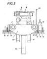
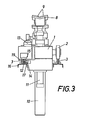
- the conveyor system shown consists essentially of a coil carriage 1, which can be moved on rollers 2 along two rails 3.
- the conveyor line formed in this way extends from a support 4 for the sheet metal coils 5 via an intermediate support 6 to a reel 7, on the mandrel of which the sheet metal coils must be attached.
- the coil carriage 1 has a lifting table 8 with a collar support 9, which is mounted in the coil carriage 1 so as to be vertically displaceable by means of a guide column 10 and can be raised and lowered by means of two cylinders 11.
- a rack 12 is laid along the conveyor path, which meshes with a gear 14 which can be driven by a motor 13.
- the gearwheel 14, which has a vertical axis of rotation, is combined with the motor 13 to form a unit which can be attached to the coil carriage 1, so that existing coil carriages can also be equipped with such a drive. Due to the selected vertical rolling surface of the rack and pinion drive, there is the advantage that wear on the running rails can have no influence on the meshing of the teeth.
- one of the running rails 3 is designed as a guide rail for two pairs of guide rollers 15 of the collar carriage 1.
- the rollers 2 are therefore also free from tasks of lateral guidance and need not have flanges, which greatly simplifies the construction of the wheels.
- the rack 12 which is preferably associated with the guide rail 15 cooperating with the guide rail 15 and fastened to it on a carrier 16, serves not only to drive the trolley 1, but also to record its position on the conveyor line.
- the toothed rack 12 serves as an incremental scale of a length measuring device which, in addition to the incremental scale, comprises a scanning unit 17 provided on the coil carriage 1 with two scanning heads 18 and 19 which are connected to a counter (not shown).
- the scanning head 18 cooperating with the rack 12 generates a pulse when passing over each tooth or tooth gap of the rack 12, which is counted by the counter. Given the predetermined distance of the teeth and tooth gaps from one another, the number of counted scanning pulses thus represents a measure of the adjustment path of the collar carriage 1.
- a reference mark 20 provided on the toothed rack 12 or on the carrier 16 (FIG. 5 ) generates a set pulse for the counter, which is either set to zero when this set pulse occurs or accepts a reference value, for example stored in a memory, as the count.
- a reference value for example stored in a memory
- the described length measuring device can also be used to determine the height of the collar and the central placement of the bundles on the coil carriage or on the intermediate support 6. If a stationary switch 21, for example a light barrier running transversely to the conveying direction, is provided, a switching impulse can be obtained when a bundle moves past, if the front and rear end faces of the bundles are moved past the switch 21. The number of scanning pulses of the rack 12 counted between the two switching pulses therefore indicates the height of the respective coil 5. With a separate counter, which is started and stopped via the switch 21, an immediate detection of the bundle height is possible.
- the central depositing of the sheet metal coils 5 on the intermediate support 6 is ensured in a simple manner, because the distance of the switch 21 from the center of the support is given.
- the coil carriage only needs to be moved by its position when the second switching pulse of the switch 21 occurs by a distance towards the intermediate support 6, which distance corresponds to the distance between the switch 21 and the center of the support reduced by half the height of the collar.
- Another possibility of the bundle height detection is to assign the bundle carriage 1 a switch 23 which responds to the sheet metal bundles 5 and which generates corresponding switching impulses on the underside of the bundles 5 resting on the supports 4 or 6.
- the determination of the respective collar height can be carried out not only in an analogous manner, but also the central placement of the sheet bundle on the lifting table 8, regardless of the position of the sheet bundles 5 on the support 4 (or 6).
- the switch 23 therefore ensures, in cooperation with the length measuring device provided for the position detection of the coil carriage, a significant simplification with regard to the feeding and depositing of the bundles 5, because a central alignment of the bundles with respect to the intended supports is not necessary. A common support for several coils can thus also be provided.
Landscapes
- Engineering & Computer Science (AREA)
- Mechanical Engineering (AREA)
- Measurement Of Length, Angles, Or The Like Using Electric Or Magnetic Means (AREA)
Claims (6)
Applications Claiming Priority (2)
| Application Number | Priority Date | Filing Date | Title |
|---|---|---|---|
| AT1342/81 | 1981-03-23 | ||
| AT134281A AT368410B (de) | 1981-03-23 | 1981-03-23 | Foerderanlage fuer blechbunde |
Publications (3)
| Publication Number | Publication Date |
|---|---|
| EP0061557A2 EP0061557A2 (fr) | 1982-10-06 |
| EP0061557A3 EP0061557A3 (en) | 1983-02-16 |
| EP0061557B1 true EP0061557B1 (fr) | 1985-01-16 |
Family
ID=3511823
Family Applications (1)
| Application Number | Title | Priority Date | Filing Date |
|---|---|---|---|
| EP19810890175 Expired EP0061557B1 (fr) | 1981-03-23 | 1981-10-22 | Convoyeur pour nappes de tôle |
Country Status (3)
| Country | Link |
|---|---|
| EP (1) | EP0061557B1 (fr) |
| AT (1) | AT368410B (fr) |
| DE (1) | DE3168383D1 (fr) |
Families Citing this family (13)
| Publication number | Priority date | Publication date | Assignee | Title |
|---|---|---|---|---|
| DE10256011A1 (de) * | 2002-11-30 | 2004-06-09 | Sms Demag Ag | Transportwagen für Metallbunde |
| EP2444171A1 (fr) * | 2010-10-22 | 2012-04-25 | Siemens VAI Metals Technologies GmbH | Système de transport, chariot transporteur et procédé de transport de bobines métalliques |
| CN107777269A (zh) * | 2016-08-26 | 2018-03-09 | 江苏三环实业股份有限公司 | 一种用于极板连续固化干燥室的输送系统 |
| CN110589359A (zh) * | 2019-10-15 | 2019-12-20 | 连云港杜钟新奥神氨纶有限公司 | 氨纶丝专用输送线 |
| CN113263087A (zh) * | 2021-05-13 | 2021-08-17 | 东风柳州汽车有限公司 | 一种滚边工作站 |
| CN114056873B (zh) * | 2021-12-15 | 2023-04-18 | 广州第七轴智能设备有限公司 | 一种筒纱输送装置 |
| CN114291521B (zh) * | 2022-01-19 | 2023-12-19 | 中冶赛迪工程技术股份有限公司 | 环形钢卷运输系统 |
| CN114700389B (zh) * | 2022-04-15 | 2024-06-04 | 北京首钢自动化信息技术有限公司 | 一种带钢卷取设备、钢卷卸卷控制方法及装置 |
| CN115502240A (zh) * | 2022-10-19 | 2022-12-23 | 山东钢铁集团日照有限公司 | 一种自动上钢卷装置及其上钢卷方法 |
| CN117602295A (zh) * | 2023-12-04 | 2024-02-27 | 青岛雷霆重工股份有限公司 | 高线大盘卷输送系统横移小车 |
| CN117923130B (zh) * | 2024-01-10 | 2026-05-12 | 福建省威诺数控有限公司 | 一种多工位物料转运方法 |
| CN118637285A (zh) * | 2024-07-03 | 2024-09-13 | 宝镁特(上海)智能工程有限公司 | 一种升降装置的钢卷运输小车及使用方法 |
| CN120438434B (zh) * | 2025-07-11 | 2025-10-10 | 湖南沁钞智能装备有限公司 | 一种不锈钢卷板送料机及其使用方法 |
Family Cites Families (1)
| Publication number | Priority date | Publication date | Assignee | Title |
|---|---|---|---|---|
| DK106075C (da) * | 1962-09-05 | 1966-12-12 | Sverre Munck | Skinnegående dækskran til skibe. |
-
1981
- 1981-03-23 AT AT134281A patent/AT368410B/de not_active IP Right Cessation
- 1981-10-22 EP EP19810890175 patent/EP0061557B1/fr not_active Expired
- 1981-10-22 DE DE8181890175T patent/DE3168383D1/de not_active Expired
Also Published As
| Publication number | Publication date |
|---|---|
| EP0061557A3 (en) | 1983-02-16 |
| ATA134281A (de) | 1982-02-15 |
| EP0061557A2 (fr) | 1982-10-06 |
| DE3168383D1 (en) | 1985-02-28 |
| AT368410B (de) | 1982-10-11 |
Similar Documents
| Publication | Publication Date | Title |
|---|---|---|
| DE69102822T2 (de) | Aufbau für programmgesteuertes Behandeln und Transportieren von Gefässen und Behältern oder ähnlichen. | |
| EP0479764B1 (fr) | Machine pour le contrôle du fil de contact d'un caténaire | |
| DE3046611C2 (fr) | ||
| EP1862411B1 (fr) | Système de galets et son procédé de commande | |
| EP0061557A2 (fr) | Convoyeur pour nappes de tôle | |
| EP0849201B1 (fr) | Méthode pour détecter et positioner un rouleau de remplacement | |
| AT389690B (de) | Regalfoerderzeug | |
| DE3524922A1 (de) | Vorrichtung zum austauschen leerer kannen gegen gefuellte kannen an einer kannenstellplaetze aufweisenden spinnmaschine | |
| DE2331916A1 (de) | Vorrichtung zum messen der seitlichen lage eines gleises zum nachbargleis | |
| EP0082442B1 (fr) | Machine de mesure pour trois coordonnées | |
| CH623624A5 (fr) | ||
| DE4429254A1 (de) | Gestell zur Aufnahme von Faserbandkannen | |
| EP0102940B1 (fr) | Dispositif pour ficeler des bobines | |
| DE3500717C2 (de) | Schweißmaschine für Drahtgitter insbesondere für Betonbewehrungszwecke | |
| EP0290877B1 (fr) | Dispositif de reprise automatique de récipients vides | |
| DE1531085B1 (de) | Vorrichtung zum Zentrieren von Blechbunden oder anderem,schwerem Foerdergut an einer Aufsetzstelle eines Tragbalkenfoerderers | |
| DE3734556C2 (fr) | ||
| EP0770153B1 (fr) | Procede et dispositif de chargement des broches a bobines d'un ratelier de bobines | |
| DE2804705C2 (de) | Einrichtung und Verfahren zur Identifizierung von Gußformen einer Gießstraße | |
| DE3310058C2 (fr) | ||
| DE3308044A1 (de) | Messmaschine zur teilungsmessung von zaehnen | |
| DE2456135C3 (de) | Einrichtung zum Messen der Position eines beweglichen Maschinenteils | |
| DE3505200C2 (de) | Antriebsvorrichtung für Parkeinrichtungen für Kraftfahrzeuge | |
| AT394687B (de) | Maschine zur kontrolle des fahrdrahtes einer oberleitung | |
| DE1239343B (de) | Gleisrichtmaschine |
Legal Events
| Date | Code | Title | Description |
|---|---|---|---|
| PUAI | Public reference made under article 153(3) epc to a published international application that has entered the european phase |
Free format text: ORIGINAL CODE: 0009012 |
|
| AK | Designated contracting states |
Designated state(s): BE CH DE FR GB IT LU NL SE |
|
| PUAL | Search report despatched |
Free format text: ORIGINAL CODE: 0009013 |
|
| AK | Designated contracting states |
Designated state(s): BE CH DE FR GB IT LI LU NL SE |
|
| 17P | Request for examination filed |
Effective date: 19830301 |
|
| ITF | It: translation for a ep patent filed | ||
| GRAA | (expected) grant |
Free format text: ORIGINAL CODE: 0009210 |
|
| AK | Designated contracting states |
Designated state(s): BE CH DE FR GB IT LI LU NL SE |
|
| REF | Corresponds to: |
Ref document number: 3168383 Country of ref document: DE Date of ref document: 19850228 |
|
| ET | Fr: translation filed | ||
| PLBI | Opposition filed |
Free format text: ORIGINAL CODE: 0009260 |
|
| PG25 | Lapsed in a contracting state [announced via postgrant information from national office to epo] |
Ref country code: LU Free format text: LAPSE BECAUSE OF NON-PAYMENT OF DUE FEES Effective date: 19851031 |
|
| 26 | Opposition filed |
Opponent name: SMS SCHLOEMANN-SIEMAG AG Effective date: 19851015 |
|
| NLR1 | Nl: opposition has been filed with the epo |
Opponent name: SMS SCHLOEMANN-SIEMAG AG |
|
| PGFP | Annual fee paid to national office [announced via postgrant information from national office to epo] |
Ref country code: FR Payment date: 19890914 Year of fee payment: 9 |
|
| PGFP | Annual fee paid to national office [announced via postgrant information from national office to epo] |
Ref country code: SE Payment date: 19890918 Year of fee payment: 9 Ref country code: DE Payment date: 19890918 Year of fee payment: 9 Ref country code: CH Payment date: 19890918 Year of fee payment: 9 |
|
| PGFP | Annual fee paid to national office [announced via postgrant information from national office to epo] |
Ref country code: BE Payment date: 19890919 Year of fee payment: 9 |
|
| PGFP | Annual fee paid to national office [announced via postgrant information from national office to epo] |
Ref country code: LU Payment date: 19890920 Year of fee payment: 9 |
|
| PGFP | Annual fee paid to national office [announced via postgrant information from national office to epo] |
Ref country code: GB Payment date: 19890930 Year of fee payment: 9 |
|
| ITTA | It: last paid annual fee | ||
| PGFP | Annual fee paid to national office [announced via postgrant information from national office to epo] |
Ref country code: NL Payment date: 19891031 Year of fee payment: 9 |
|
| PG25 | Lapsed in a contracting state [announced via postgrant information from national office to epo] |
Ref country code: GB Effective date: 19901022 |
|
| PG25 | Lapsed in a contracting state [announced via postgrant information from national office to epo] |
Ref country code: SE Effective date: 19901023 |
|
| PG25 | Lapsed in a contracting state [announced via postgrant information from national office to epo] |
Ref country code: LI Free format text: LAPSE BECAUSE OF NON-PAYMENT OF DUE FEES Effective date: 19901031 Ref country code: CH Free format text: LAPSE BECAUSE OF NON-PAYMENT OF DUE FEES Effective date: 19901031 Ref country code: BE Effective date: 19901031 |
|
| BERE | Be: lapsed |
Owner name: VOEST-ALPINE A.G. Effective date: 19901031 |
|
| PG25 | Lapsed in a contracting state [announced via postgrant information from national office to epo] |
Ref country code: NL Effective date: 19910501 |
|
| NLV4 | Nl: lapsed or anulled due to non-payment of the annual fee | ||
| GBPC | Gb: european patent ceased through non-payment of renewal fee | ||
| PG25 | Lapsed in a contracting state [announced via postgrant information from national office to epo] |
Ref country code: FR Effective date: 19910628 |
|
| REG | Reference to a national code |
Ref country code: CH Ref legal event code: PL |
|
| PG25 | Lapsed in a contracting state [announced via postgrant information from national office to epo] |
Ref country code: DE Effective date: 19910702 |
|
| REG | Reference to a national code |
Ref country code: FR Ref legal event code: ST |
|
| RDAG | Patent revoked |
Free format text: ORIGINAL CODE: 0009271 |
|
| STAA | Information on the status of an ep patent application or granted ep patent |
Free format text: STATUS: PATENT REVOKED |
|
| 27W | Patent revoked |
Effective date: 19920413 |
|
| EUG | Se: european patent has lapsed |
Ref document number: 81890175.3 Effective date: 19910603 |
|
| APAH | Appeal reference modified |
Free format text: ORIGINAL CODE: EPIDOSCREFNO |