EP0770153B1 - Procede et dispositif de chargement des broches a bobines d'un ratelier de bobines - Google Patents
Procede et dispositif de chargement des broches a bobines d'un ratelier de bobines Download PDFInfo
- Publication number
- EP0770153B1 EP0770153B1 EP95909644A EP95909644A EP0770153B1 EP 0770153 B1 EP0770153 B1 EP 0770153B1 EP 95909644 A EP95909644 A EP 95909644A EP 95909644 A EP95909644 A EP 95909644A EP 0770153 B1 EP0770153 B1 EP 0770153B1
- Authority
- EP
- European Patent Office
- Prior art keywords
- sensor
- pins
- frame
- carriage
- stored
- Prior art date
- Legal status (The legal status is an assumption and is not a legal conclusion. Google has not performed a legal analysis and makes no representation as to the accuracy of the status listed.)
- Expired - Lifetime
Links
- 238000000034 method Methods 0.000 title claims abstract description 24
- 238000012546 transfer Methods 0.000 claims abstract description 17
- 230000001960 triggered effect Effects 0.000 claims abstract description 9
- 238000005259 measurement Methods 0.000 claims description 10
- 238000000926 separation method Methods 0.000 claims 3
- 238000004891 communication Methods 0.000 claims 1
- 238000010276 construction Methods 0.000 description 2
- 238000013461 design Methods 0.000 description 2
- 238000006073 displacement reaction Methods 0.000 description 2
- 238000005516 engineering process Methods 0.000 description 2
- 240000004752 Laburnum anagyroides Species 0.000 description 1
- 230000003139 buffering effect Effects 0.000 description 1
- 238000012937 correction Methods 0.000 description 1
- 230000001419 dependent effect Effects 0.000 description 1
- 238000011144 upstream manufacturing Methods 0.000 description 1
- 238000004804 winding Methods 0.000 description 1
Images

Classifications
-
- D—TEXTILES; PAPER
- D02—YARNS; MECHANICAL FINISHING OF YARNS OR ROPES; WARPING OR BEAMING
- D02H—WARPING, BEAMING OR LEASING
- D02H1/00—Creels, i.e. apparatus for supplying a multiplicity of individual threads
-
- B—PERFORMING OPERATIONS; TRANSPORTING
- B65—CONVEYING; PACKING; STORING; HANDLING THIN OR FILAMENTARY MATERIAL
- B65H—HANDLING THIN OR FILAMENTARY MATERIAL, e.g. SHEETS, WEBS, CABLES
- B65H67/00—Replacing or removing cores, receptacles, or completed packages at paying-out, winding, or depositing stations
- B65H67/06—Supplying cores, receptacles, or packages to, or transporting from, winding or depositing stations
- B65H67/064—Supplying or transporting cross-wound packages, also combined with transporting the empty core
-
- B—PERFORMING OPERATIONS; TRANSPORTING
- B65—CONVEYING; PACKING; STORING; HANDLING THIN OR FILAMENTARY MATERIAL
- B65H—HANDLING THIN OR FILAMENTARY MATERIAL, e.g. SHEETS, WEBS, CABLES
- B65H2701/00—Handled material; Storage means
- B65H2701/30—Handled filamentary material
- B65H2701/31—Textiles threads or artificial strands of filaments
-
- Y—GENERAL TAGGING OF NEW TECHNOLOGICAL DEVELOPMENTS; GENERAL TAGGING OF CROSS-SECTIONAL TECHNOLOGIES SPANNING OVER SEVERAL SECTIONS OF THE IPC; TECHNICAL SUBJECTS COVERED BY FORMER USPC CROSS-REFERENCE ART COLLECTIONS [XRACs] AND DIGESTS
- Y10—TECHNICAL SUBJECTS COVERED BY FORMER USPC
- Y10S—TECHNICAL SUBJECTS COVERED BY FORMER USPC CROSS-REFERENCE ART COLLECTIONS [XRACs] AND DIGESTS
- Y10S414/00—Material or article handling
- Y10S414/121—Perforated article handling
Definitions
- the invention relates to a method for loading the spool of a creel or the like. with full Spools of thread placed on top of one another by a pick and place device arranged horizontal mandrels of a dolly be plugged in by a traction motor between the placement device and move the gate rail bound and with a sensor in a predetermined position before Gatter is positioned where the wagon arbors with thorns of Gatters s worn.
- the invention is therefore based on the object of a method to improve with the features mentioned at the beginning, that time-consuming and complicated setup of positioning of the trolley before and during execution of the procedure can be avoided.
- This object is achieved in that the sensor the height of a mandrel day of the gate is aligned that the routes of the trolley stored in its process be that sensor signals triggered by gate thorns are saved depending on the route, and that the trolley with the stored sensor signals is controlled in its coil transfer positions.
- the position the gate mandrels are measured automatically and the transport trolley can be controlled according to the measurement result.
- the Measurement the positions of the gate mandrels of a mandrel day can repeated at any time to change positions the gate arbors to be detected, such as in gates occur with chains with which the coil rows are positioned become.
- the positioning of the vertical rows of coils or gate mandrels can by the flexibility of the chains or are influenced by chain elongation.
- One is able to process the positions the gate thorns again and again at short intervals determine. It is even possible to position the mandrels to be checked at the same time as an assembly process and to compare with the stored values, if necessary Make corrections immediately or afterwards to be able to. In this way, the control of the trolley be influenced immediately, especially by Interest is when assembling a creel equipped with a transport trolley that has only a single row of wagons and the entire gate in particular in a row in succession equipped.
- the wagon arbors not only have to be positioned horizontally the gate arbors must be tuned, but it must also different rail levels and vertical arrangements the gate arbors above the rail level are taken into account, as well as gates with offset division.
- To be vertically different Detecting positions of gate arbors will the procedure performed so that a vertically adjustable Sensor of the trolley on a vertical row of mandrels of the Gate aligned and moved vertically that of of the vertical mandrel row triggered sensor signals depending on the mandrel distance be saved, and that vertically adjustable Wagendorne adjusted according to the stored sensor signals become.
- This method can be very different Distances between the lowest mandrel of a row of gates and a reference level, e.g. Rail level are taken into account to adjust the wagon arbor vertically so that it the gate thorns.
- the invention also relates to a device for Load the coil mandrels of a creel with full ones Spools of thread, with a loading device that the full Coils of a coil supply on horizontal superimposed ones Put on the spikes of a dolly, one of them Traction motor between the placement device and the gate Rail-bound movable and with a sensor in a predetermined Position in front of the gate is positionable in the the wagon arbors aligned with thorns of the gate.
- the device is designed so that the sensor is aligned with the height of a mandrel day of the gate is that one of the routes of the dolly in the method of storing distance measuring device available is that signals of the gate triggered by thorns of the gate Sensor depending on the measurement result of the distance measuring device are storable, and that the traction motor of the Transport carriage whose coil transfer positions the saved Can control sensor signals according to.
- a distance measuring device known technology can be used, so that the device is not only time-consuming and complicated Setup work for horizontal changes in position of the gate mandrels avoids, but also with simple and proven means.
- a vertically adjustable sensor is available on the transport trolley is that of a vertical row of thorns of the gate triggered signals of this sensor from a height distance measuring device are storable, and that the Wagendorne vertically adjusting actuator these mandrels the stored Can adjust sensor signals according to.
- Height measurement device can use proven technology so that the device not only solves the problem, vertical changes in distance or vertically different set mandrels with respect to their vertical position to measure quickly and repeatably, but it can in addition, with simple and proven means can be achieved.
- the device has sufficient accuracy, for example then when the traction motor and / or the actuator drive a high-resolution encoder that works with the Distance measuring device and / or with the height distance measuring device is in measurement connection.
- high-resolution encoders are, for example, incremental encoders that are based on their Measuring connection to the distance measuring device and / or to the Height distance measuring device continuous storage of the measured variables enable.
- the device is designed so that the distance measuring device and / or the height distance measuring device a programmable logic controller can be connected.
- the programs stored in the control become the assembly process utilizing the measurement results of the Distance measuring device and the height distance measuring device so controlled that stocked with minimal time even with pattern-dependent equipment. It is possible, especially with a permanent measurement connection that the Transport trolleys with different vertical coil rows controlled by the process computer starts, for example depending from a warp pattern to be subtracted from the gate Threads.
- the programmable Control is arranged on the placement device.
- the programmable logic controller is central to be used for all bobbin wagons if assumed is that there is only a single placement device is. Even if a single placement device for several Gate is used, this is the most convenient solution since the construction effort is least.
- connection of the programmed control to the Distance measuring device and / or to the height distance measuring device can be permanent, for example if the programmable Control arranged on the trolley or if between the dolly and the assembly and the programmable logic controller a continuous mechanical or wireless connection is possible. Can this an exchange cannot be achieved with simple means between the programmable controller on the one hand and the two measuring devices on the other hand, for example instead of when the trolley is loaded in the Is arranged near the placement device.
- the device In order for the device to be as universal as possible To achieve, it is designed so that the vertical adjustable sensor lower in its basic position stands as the deepest gate thorn, and that the lowest thorn the placement device reference point for the vertical adjustable sensor is.
- the trolley can then for different gates are used, also in connection with assembly devices, the mandrels of which differ vertically are arranged high and / or adjustable.
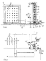
- FIG. 1 shows a gate 11 with tiers and with rows arranged mandrels 10 for receiving coils, whose threads from a winding machine, not shown in are known to be deducted. So it's horizontal Mandrel days a, b, c, d, e, f present, the mandrels 10 on the other hand form vertical mandrel rows 1, 2 and 3. So that the mandrels 10 with full bobbin can be loaded if the threads of the previous bobbins are unwound, a dolly will 15 used between the gate 11 and a placement device 13 in the directions of the double arrow 32 can travel back and forth by rail. In Fig.3 there is one Rail 14 shown in cross section.
- the transport carriage 15 has a carriage frame 25 with rollers 26, one of which has a drive motor 23 via a Belt drive 27 is driven in rotation.
- the carriage frame 25 has also several wagons 16 in a row of thorns one above the other arranged.
- Flexible adjustment means 28, e.g. chain driven Holding plates, are able to adjust the mandrels 16 vertically, the carriage frame 25 above and below pulleys 29 has.
- the coil carriage 15 is to be converted so that for example by replacing the adjusting means 28 others, which have mandrels 16 with the required spacing.
- the carriage 15 is arranged in its zero position, that defined in relation to the placement device 13 is. From this zero position, the carriage 15 with the Traction motor 23 can be moved to gate 11 after it from the assembly device 13 is equipped with full bobbins 12 has been. It must be stopped in front of gate 11 in such a way that its mandrels 16 are aligned with the mandrels 10 of the gate 11. In order to guarantee this, the control must be correspondingly precise and automatically influenced to the desired positioning to reach.
- a programmable logic controller PLC used, which the Control of the traction motor 23 in a conventional manner, i.e.
- Fig.2 is the arrangement of the programmable logic controller PLC the placement device 13 shown to express bring that from here the all-master control done when loading.
- a programmable logic controller SPS can also be present on a transport trolley to control its movement and work processes.
- the placement device can also function from the car 13 are influenced, unless one prefers the programmable logic controller PLC of the trolley 15 to train as a wagon control and a higher-level control programmable logic control of the placement device 13 subordinate.
- the transport carriage 15 or its drive motor 23 has a high-resolution displacement sensor 24, which is designed as an incremental sensor.
- a high-resolution displacement sensor 24 is designed as an incremental sensor.
- Fig.3 shows that the trolley 15 has an actuator 22 for horizontal adjustment of the adjustment means 28 and thus the wagon arbor has 16.
- a high-resolution encoder 24 is attached, which acts as an incremental encoder is trained.
- a vertically adjustable Sensor 19 is present and its signals are from a height distance measuring device 21 storable on the assembly device 13 is present. This sensor 19 is on the lowest mandrel 31 of the placement device 13 as a reference point set. From this position, in which the Sensor 19 faces the mandrel 31 exactly, the vertical increments are counted and saved accordingly.
- the programmable logic controller PLC in operative connection with the height distance measuring device 21 can influence the vertical position of the carriage mandrel 16 after the full Coils 12 were passed from the placement device 13 to the carriage 15. There is then a one-time adjustment of the height of the mandrels 16 in accordance with the measurement result of the counting travel in the y n direction or from row of rows to row of rows, as far as this is necessary, for example in the case of gates with a vertically offset division.
Landscapes
- Engineering & Computer Science (AREA)
- Textile Engineering (AREA)
- Replacing, Conveying, And Pick-Finding For Filamentary Materials (AREA)
- Moulding By Coating Moulds (AREA)
- Replacement Of Web Rolls (AREA)
Abstract
Claims (9)
- Procédé pour garnir les broches de bobines (10) d'un cantre (11), ou d'un dispositif similaire, avec des bobines de fil pleines (12) qui sont enfilées par un dispositif de garnissage (13) sur des broches horizontales superposées (16) d'un chariot de transport (15), lequel chariot est déplacé sur rails par un moteur de translation (23) entre le dispositif de garnissage (13) et le cantre (11) et est positionné à l'aide d'un capteur (25) dans une position prédéfinie devant le cantre (11), où les broches de chariot (16) se trouvent dans l'alignement de broches (10) du cantre (11), caractérisé en ce que le capteur (25) est placé à la hauteur d'un étage de broches (b) du cantre (11), en ce que les trajets (par exemple x1) du chariot de transport (15) lors de son déplacement sont mis en mémoire, en ce que des signaux de capteur déclenchés par des broches de cantre (10) sont mis en mémoire en fonction des trajets (par exemple x1), et en ce que le chariot (15) est dirigé à l'aide des signaux de capteurs mis en mémoire vers ses positions de transfert de bobines.
- Procédé selon la revendication 1, caractérisé en ce qu'un capteur (19), réglable verticalement, du chariot de transport (15) est aligné sur une rangée de broches verticale (1) du cantre (11) et est déplacé verticalement, en ce que les signaux de capteur déclenchés par la rangée de broches verticale (1) sont mis en mémoire en fonction de l'écart entre les broches, et en ce que des broches de chariot (16) réglables verticalement sont réglées suivant les signaux de capteur mis en mémoire.
- Dispositif pour garnir les broches de bobines (10) d'un cantre (11) avec des bobines de fil pleines (12), comportant un dispositif de garnissage (13) qui enfile les bobines pleines (12) d'une réserve de bobines sur des broches horizontales superposées (16) d'un chariot de transport (15), lequel chariot est apte à être déplacé sur rails par un moteur de translation (23) entre le dispositif de garnissage (13) et le cantre (11) et est apte à être positionné à l'aide d'un capteur (25) dans une position prédéfinie devant le cantre (11), dans laquelle les broches de chariot (16) se trouvent dans l'alignement de broches (10) du cantre (11), caractérisé en ce que le capteur (25) est placé à la hauteur d'un étage de broches (b) du cantre, en ce qu'il est prévu un dispositif de mesure de trajet (18) qui met en mémoire les trajets (par exemple xl) du chariot de transport (15) lors du déplacement de celui-ci, en ce que des signaux du capteur (25) déclenchés par des broches (10) du cantre (11) sont aptes à être mis en mémoire en fonction du résultat de mesure du dispositif de mesure de trajet (18), et en ce que le moteur de translation (23) du chariot de transport (15) peut commander les positions de transfert de bobines de celui-ci suivant les signaux de capteur mis en mémoire.
- Dispositif selon la revendication 3, caractérisé en ce qu'il est prévu sur le chariot de transport (15) un capteur (19) réglable verticalement, en ce que des signaux de ce capteur (19) déclenchés par les broches (10) d'une rangée de broches verticale (1) du cantre (11) sont aptes à être mis en mémoire par le dispositif de mesure d'écartement en hauteur (21), et en ce qu'un mécanisme de commande (22) qui déplace verticalement les broches de chariot (16) peut déplacer ces broches (16) en fonction des signaux de capteur mis en mémoire.
- Dispositif selon la revendication 4, caractérisé en ce que le capteur (19) réglable verticalement est apte à être déplacé avec les broches de chariot (16) par le mécanisme de commande (22) de celles-ci.
- Dispositif selon l'une des revendications 3 à 5, caractérisé en ce que le moteur de translation (23) et/ou le mécanisme de commande (22) entraínent un générateur de course à haute résolution (24) qui est relié par une relation de mesure au dispositif de mesure de trajet (18) et/ou au dispositif de mesure d'écartement en hauteur (21).
- Dispositif selon l'une des revendications 3 à 6, caractérisé en ce que le dispositif de mesure de trajet (18) et/ou le dispositif de mesure d'écartement en hauteur (21) sont aptes à être reliés à un automate programmable industriel (API).
- Dispositif selon la revendication 7, caractérisé en ce que l'automate programmable industriel (API) est disposé sur le dispositif de garnissage (13).
- Dispositif selon l'une des revendications 4 à 8, caractérisé en ce que le capteur (19) réglable verticalement se trouve plus bas, dans sa position de base, que la broche de cantre (10) la plus basse, et en ce que la broche inférieure (31) du dispositif de garnissage (13) constitue le point de référence pour le capteur (19) réglable verticalement.
Applications Claiming Priority (3)
| Application Number | Priority Date | Filing Date | Title |
|---|---|---|---|
| DE4409522 | 1994-03-19 | ||
| DE4409522A DE4409522A1 (de) | 1994-03-19 | 1994-03-19 | Verfahren und Vorrichtung zum Bestücken der Spulendorne eines Spulengatters |
| PCT/DE1995/000222 WO1995025835A1 (fr) | 1994-03-19 | 1995-02-22 | Procede et dispositif de chargement des broches a bobines d'un ratelier de bobines |
Publications (2)
| Publication Number | Publication Date |
|---|---|
| EP0770153A1 EP0770153A1 (fr) | 1997-05-02 |
| EP0770153B1 true EP0770153B1 (fr) | 1999-01-13 |
Family
ID=6513313
Family Applications (1)
| Application Number | Title | Priority Date | Filing Date |
|---|---|---|---|
| EP95909644A Expired - Lifetime EP0770153B1 (fr) | 1994-03-19 | 1995-02-22 | Procede et dispositif de chargement des broches a bobines d'un ratelier de bobines |
Country Status (5)
| Country | Link |
|---|---|
| US (1) | US5829950A (fr) |
| EP (1) | EP0770153B1 (fr) |
| DE (2) | DE4409522A1 (fr) |
| ES (1) | ES2128713T3 (fr) |
| WO (1) | WO1995025835A1 (fr) |
Cited By (1)
| Publication number | Priority date | Publication date | Assignee | Title |
|---|---|---|---|---|
| CN105200604A (zh) * | 2015-08-21 | 2015-12-30 | 孙维 | 一种整经机的纱架 |
Families Citing this family (2)
| Publication number | Priority date | Publication date | Assignee | Title |
|---|---|---|---|---|
| US6845327B2 (en) | 2001-06-08 | 2005-01-18 | Epocal Inc. | Point-of-care in-vitro blood analysis system |
| EP4428081A1 (fr) * | 2023-03-10 | 2024-09-11 | Superba | Système pour le chargement d'emballages de fil sur un cantre |
Family Cites Families (10)
| Publication number | Priority date | Publication date | Assignee | Title |
|---|---|---|---|---|
| DE3244917A1 (de) * | 1982-12-04 | 1984-06-14 | W. Schlafhorst & Co, 4050 Mönchengladbach | Spulentransportvorrichtung |
| JPS61111282A (ja) * | 1984-11-02 | 1986-05-29 | Murata Mach Ltd | ワ−パ−クリ−ルへのパツケ−ジ供給装置 |
| JPH0759460B2 (ja) * | 1986-01-27 | 1995-06-28 | 村田機械株式会社 | クリ−ルへのパッケ−ジ供給装置 |
| JPS6347208A (ja) * | 1986-08-18 | 1988-02-29 | Daifuku Co Ltd | 荷捌装置のインタ−ロツク方法 |
| JPS6481771A (en) * | 1987-07-21 | 1989-03-28 | Murata Machinery Ltd | Package feeding device to paper creel |
| DE59009286D1 (de) * | 1989-04-07 | 1995-07-27 | Rieter Ingolstadt Spinnerei | Verfahren und vorrichtung zum transport von spulen oder spulenähnlichen gütern der textilindustrie. |
| US5207547A (en) * | 1989-04-25 | 1993-05-04 | Murata Kikai Kabushiki Kaisha | Package replacing apparatus |
| US5091685A (en) * | 1989-10-19 | 1992-02-25 | Harnischfeger Engineers, Inc. | Method and apparatus for controlling the shuttle of a storage and retrieval machine |
| JPH0418683U (fr) * | 1990-06-01 | 1992-02-17 | ||
| DE9010098U1 (de) * | 1990-07-03 | 1991-11-07 | Hacoba Textilmaschinen Gmbh & Co Kg, 5600 Wuppertal | Vorrichtung zum Bestücken der Spulendorne eines Spulengatters |
-
1994
- 1994-03-19 DE DE4409522A patent/DE4409522A1/de not_active Withdrawn
-
1995
- 1995-02-22 EP EP95909644A patent/EP0770153B1/fr not_active Expired - Lifetime
- 1995-02-22 WO PCT/DE1995/000222 patent/WO1995025835A1/fr not_active Ceased
- 1995-02-22 DE DE59504830T patent/DE59504830D1/de not_active Expired - Fee Related
- 1995-02-22 ES ES95909644T patent/ES2128713T3/es not_active Expired - Lifetime
- 1995-02-22 US US08/718,422 patent/US5829950A/en not_active Expired - Fee Related
Cited By (2)
| Publication number | Priority date | Publication date | Assignee | Title |
|---|---|---|---|---|
| CN105200604A (zh) * | 2015-08-21 | 2015-12-30 | 孙维 | 一种整经机的纱架 |
| CN105200604B (zh) * | 2015-08-21 | 2017-07-28 | 邓红梅 | 一种整经机的纱架 |
Also Published As
| Publication number | Publication date |
|---|---|
| DE4409522A1 (de) | 1995-09-21 |
| ES2128713T3 (es) | 1999-05-16 |
| DE59504830D1 (de) | 1999-02-25 |
| US5829950A (en) | 1998-11-03 |
| WO1995025835A1 (fr) | 1995-09-28 |
| EP0770153A1 (fr) | 1997-05-02 |
Similar Documents
| Publication | Publication Date | Title |
|---|---|---|
| EP0709501B1 (fr) | Procédé pour remplacer des pots entre un chariot de transport pour pots plats et un métier à filer à bout libre et chariot de transport pour la mise en oeuvre de ce procédé | |
| DE19726831C2 (de) | Multiaxial-Maschine mit Portalaufbau | |
| DE2126860A1 (de) | Maschine zur Ausbildung von Kabelbäumen | |
| DE19927419A1 (de) | Überwachungseinrichtung für ein Ende eines auf einer Vorratsspule aufgewickelten fadenförmigen Gutes sowie Verfahren hierfür | |
| DE3635576C2 (de) | Verfahren und Anlage zum Vorgarnspulenwechsel | |
| DE4429254C2 (de) | Faserbandkannentransportersystem | |
| DE8321639U1 (de) | Vorrichtung zum Ablegen von Spulen od. dgl. | |
| EP0061557A2 (fr) | Convoyeur pour nappes de tôle | |
| DE4336908A1 (de) | Wiegevorrichtung | |
| DE4127319C2 (de) | Vorrichtung zur Wegregelung bei einem Aufwickler für langgestrecktes Gut | |
| DE112018007673T5 (de) | Bauteilwiederauffüllungs- verwaltungssystem und bauteilmontage-system | |
| DE3429153A1 (de) | Textilmaschine | |
| EP0770153A1 (fr) | Procede et dispositif de chargement des broches a bobines d'un ratelier de bobines | |
| CH663200A5 (de) | Verfahren zum erzeugen oder bearbeiten und aufwickeln von faeden. | |
| EP0628648B1 (fr) | Dispositif pour garnir les broches d'un cantre | |
| DE3734556C2 (fr) | ||
| DE2804705C2 (de) | Einrichtung und Verfahren zur Identifizierung von Gußformen einer Gießstraße | |
| EP0916613B1 (fr) | Dispositif pour alimenter en tubes une machine textile pour la production de bobines à spires croisées | |
| DE4335764C2 (de) | Vorrichtung zum geordneten Abräumen von Kreuzspulen von einem entlang einer Kreuzspulen herstellenden Maschine verlaufenden Förderband | |
| DE102010035070A1 (de) | Verfahren zum Betreiben eines Kreuzspulenwechselaggregats sowie zugehöriges Kreuzspulenwechselaggregat | |
| DE4421778A1 (de) | Vorrichtung zum selbsttätigen Zu- oder Abführen voller Spulen oder leerer Hülsen für eine Textilmaschine | |
| EP0401860A2 (fr) | Procédé et dispositif de mise en oeuvre du procédé, et agencement pour transférer ou recevoir automatiquement des bobines, en particulier de préparation à ou à partir d'une chaîne de transport | |
| EP0041918B1 (fr) | Dispositif de codage pour marques de destination de récipients | |
| DE4406484C2 (de) | Einrichtung zum selbsttätigen Zu- oder Abführen von Hülsen oder Spulen an Spinnereimaschinen | |
| DE102012108755B4 (de) | Verfahren und Bewegungsvorrichtung zur sofortigen Abweichungskorrektur im Bewegungszustand |
Legal Events
| Date | Code | Title | Description |
|---|---|---|---|
| PUAI | Public reference made under article 153(3) epc to a published international application that has entered the european phase |
Free format text: ORIGINAL CODE: 0009012 |
|
| 17P | Request for examination filed |
Effective date: 19960824 |
|
| AK | Designated contracting states |
Kind code of ref document: A1 Designated state(s): CH DE ES FR GB IT LI |
|
| GRAG | Despatch of communication of intention to grant |
Free format text: ORIGINAL CODE: EPIDOS AGRA |
|
| 17Q | First examination report despatched |
Effective date: 19980504 |
|
| GRAG | Despatch of communication of intention to grant |
Free format text: ORIGINAL CODE: EPIDOS AGRA |
|
| GRAH | Despatch of communication of intention to grant a patent |
Free format text: ORIGINAL CODE: EPIDOS IGRA |
|
| GRAH | Despatch of communication of intention to grant a patent |
Free format text: ORIGINAL CODE: EPIDOS IGRA |
|
| GRAA | (expected) grant |
Free format text: ORIGINAL CODE: 0009210 |
|
| AK | Designated contracting states |
Kind code of ref document: B1 Designated state(s): CH DE ES FR GB IT LI |
|
| REG | Reference to a national code |
Ref country code: CH Ref legal event code: EP |
|
| REF | Corresponds to: |
Ref document number: 59504830 Country of ref document: DE Date of ref document: 19990225 |
|
| PGFP | Annual fee paid to national office [announced via postgrant information from national office to epo] |
Ref country code: ES Payment date: 19990226 Year of fee payment: 5 |
|
| PGFP | Annual fee paid to national office [announced via postgrant information from national office to epo] |
Ref country code: FR Payment date: 19990301 Year of fee payment: 5 |
|
| PGFP | Annual fee paid to national office [announced via postgrant information from national office to epo] |
Ref country code: GB Payment date: 19990304 Year of fee payment: 5 |
|
| PGFP | Annual fee paid to national office [announced via postgrant information from national office to epo] |
Ref country code: CH Payment date: 19990315 Year of fee payment: 5 |
|
| REG | Reference to a national code |
Ref country code: CH Ref legal event code: NV Representative=s name: E. BLUM & CO. PATENTANWAELTE |
|
| ITF | It: translation for a ep patent filed | ||
| GBT | Gb: translation of ep patent filed (gb section 77(6)(a)/1977) |
Effective date: 19990330 |
|
| ET | Fr: translation filed | ||
| REG | Reference to a national code |
Ref country code: ES Ref legal event code: FG2A Ref document number: 2128713 Country of ref document: ES Kind code of ref document: T3 |
|
| PLBE | No opposition filed within time limit |
Free format text: ORIGINAL CODE: 0009261 |
|
| STAA | Information on the status of an ep patent application or granted ep patent |
Free format text: STATUS: NO OPPOSITION FILED WITHIN TIME LIMIT |
|
| 26N | No opposition filed | ||
| PG25 | Lapsed in a contracting state [announced via postgrant information from national office to epo] |
Ref country code: GB Free format text: LAPSE BECAUSE OF NON-PAYMENT OF DUE FEES Effective date: 20000222 |
|
| PG25 | Lapsed in a contracting state [announced via postgrant information from national office to epo] |
Ref country code: ES Free format text: LAPSE BECAUSE OF NON-PAYMENT OF DUE FEES Effective date: 20000223 |
|
| PG25 | Lapsed in a contracting state [announced via postgrant information from national office to epo] |
Ref country code: LI Free format text: LAPSE BECAUSE OF NON-PAYMENT OF DUE FEES Effective date: 20000229 Ref country code: CH Free format text: LAPSE BECAUSE OF NON-PAYMENT OF DUE FEES Effective date: 20000229 |
|
| GBPC | Gb: european patent ceased through non-payment of renewal fee |
Effective date: 20000222 |
|
| REG | Reference to a national code |
Ref country code: CH Ref legal event code: PL |
|
| PG25 | Lapsed in a contracting state [announced via postgrant information from national office to epo] |
Ref country code: FR Free format text: LAPSE BECAUSE OF NON-PAYMENT OF DUE FEES Effective date: 20001031 |
|
| REG | Reference to a national code |
Ref country code: FR Ref legal event code: ST |
|
| PGFP | Annual fee paid to national office [announced via postgrant information from national office to epo] |
Ref country code: DE Payment date: 20010406 Year of fee payment: 7 |
|
| REG | Reference to a national code |
Ref country code: ES Ref legal event code: FD2A Effective date: 20010910 |
|
| PG25 | Lapsed in a contracting state [announced via postgrant information from national office to epo] |
Ref country code: DE Free format text: LAPSE BECAUSE OF NON-PAYMENT OF DUE FEES Effective date: 20020903 |
|
| PG25 | Lapsed in a contracting state [announced via postgrant information from national office to epo] |
Ref country code: IT Free format text: LAPSE BECAUSE OF NON-PAYMENT OF DUE FEES;WARNING: LAPSES OF ITALIAN PATENTS WITH EFFECTIVE DATE BEFORE 2007 MAY HAVE OCCURRED AT ANY TIME BEFORE 2007. THE CORRECT EFFECTIVE DATE MAY BE DIFFERENT FROM THE ONE RECORDED. Effective date: 20050222 |