EP0061580A1 - Magasin d'aiguilles pour dispositifs de marquage, par exemple de la hauteur au dessus du sol du bord de vêtements - Google Patents
Magasin d'aiguilles pour dispositifs de marquage, par exemple de la hauteur au dessus du sol du bord de vêtements Download PDFInfo
- Publication number
- EP0061580A1 EP0061580A1 EP82101312A EP82101312A EP0061580A1 EP 0061580 A1 EP0061580 A1 EP 0061580A1 EP 82101312 A EP82101312 A EP 82101312A EP 82101312 A EP82101312 A EP 82101312A EP 0061580 A1 EP0061580 A1 EP 0061580A1
- Authority
- EP
- European Patent Office
- Prior art keywords
- needle
- magazine
- pin
- garment
- heads
- Prior art date
- Legal status (The legal status is an assumption and is not a legal conclusion. Google has not performed a legal analysis and makes no representation as to the accuracy of the status listed.)
- Granted
Links
- 238000000926 separation method Methods 0.000 claims description 21
- 125000006850 spacer group Chemical group 0.000 abstract 1
- 239000004744 fabric Substances 0.000 description 17
- 230000005540 biological transmission Effects 0.000 description 14
- 238000003780 insertion Methods 0.000 description 10
- 230000037431 insertion Effects 0.000 description 10
- 238000004146 energy storage Methods 0.000 description 4
- 230000006835 compression Effects 0.000 description 3
- 238000007906 compression Methods 0.000 description 3
- 239000000463 material Substances 0.000 description 3
- 230000008878 coupling Effects 0.000 description 2
- 238000010168 coupling process Methods 0.000 description 2
- 238000005859 coupling reaction Methods 0.000 description 2
- 238000006073 displacement reaction Methods 0.000 description 2
- 230000000694 effects Effects 0.000 description 2
- 238000002347 injection Methods 0.000 description 2
- 239000007924 injection Substances 0.000 description 2
- 238000001746 injection moulding Methods 0.000 description 2
- 238000000034 method Methods 0.000 description 2
- 230000000903 blocking effect Effects 0.000 description 1
- 238000010276 construction Methods 0.000 description 1
Images




Classifications
-
- A—HUMAN NECESSITIES
- A41—WEARING APPAREL
- A41H—APPLIANCES OR METHODS FOR MAKING CLOTHES, e.g. FOR DRESS-MAKING OR FOR TAILORING, NOT OTHERWISE PROVIDED FOR
- A41H9/00—Devices or methods for trimming, levelling or straightening the hems of garments
- A41H9/02—Devices for marking the length of garments
Definitions
- the invention relates to a magazine of needles for marking, for example, the height of the edges of the garment above the floor.
- the object of the invention is based on creating and providing needles for the corresponding marking so that it is ensured that with light loading of a corresponding device, needle by needle can always be safely and automatically inserted through the edge of the garment without any loss material.
- This object is achieved by combining the needles to form a needle magazine in such a way that the needles are combined on the head side to form a magazine row with predetermined separation points.
- a needle magazine is specified which is suitable for devices for marking, for example, the height of the edges of clothing above the floor.
- a larger number of needles than one unit be added, as a contiguous series of magazines.
- the device itself then detaches the respective needle to be inserted into the edge of the garment.
- the needle can be disconnected using a force-operated ram.
- the nominal separation points on the head side are designed in such a way that no separation is achieved in the usual handling of the magazine row. This is done exclusively by the device. The separation is waste-free. Burrs at the separation point do not affect the passage through the fabric.
- the needle heads have a central circumferential annular groove connecting two base plates at the ends.
- the target separation points are located exclusively on the base plates. These can have different cross sections.
- the two end-side base plates realize that the needles are always connected at two points on the head side. This has advantages with regard to good guidance of the needles, since this counteracts a mutual twisting of the needles.
- the needle heads which are made of plastic, are designed as cylinders with an annular groove on the jacket wall side and the end-side base plates of these cylinders are connected tangentially to one another to form a desired separation point.
- the cylindrical shape of the needle heads and the base plates allows small double separation points to be realized which, on the one hand, provide the magazine row with sufficient stability and, on the other hand, nevertheless enable the device to be easily removed from the respective needle to be inserted.
- the special design of the needle heads allows a needle shaft of the device not only to run in a straight line. There is a certain flexibility of the magazine row so that it can also adapt to a different course of a needle magazine slot.
- the special design of the needle heads brings the advantage of a safe insertion of the needle into the edge of the garment by means of a needle insertion plunger.
- the one base plate surrounds a thickened needle end.
- the magazine series can therefore be manufactured by injection molding.
- the thickened needle end of the needles ensures that the needles are reliably assigned to the needle heads, so that the latter cannot be removed from the needles but remain in their correct position.
- Another variant of the needle magazine is characterized in that the width of the desired separation points is narrower than the thickness of the base plates.
- the notch effect is improved, which favors the removal of the respective needle.
- Base plates are formed by two recesses arranged on opposite sides of the needle heads and lying secant to the needle head, preferably with a flat base.
- the target separation points are symmetrical between the wells.
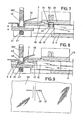
- the device that processes the needle magazines N, N ', N "indicated in FIGS. 10 to 17 has a base plate 1, from which a vertically directed column 2 extends.
- a support arm 4, which can be locked by means of a clamping toggle 3, is guided thereon encompasses the lower corner of a base plate 5 and cover plate 6 which are parallel to one another.
- a horizontally extending longitudinal slot 7 which is open on one side of the base plate. This crosses a vertically directed flexion slot 8 of the fabric flexor 9 formed by a projection of the base plate 5. As can be seen in particular from FIGS. 7 and 8, the flexion slot 8 has a smaller depth than the longitudinal slot 7.
- the base plate 5 is in the region of the fabric flexor 9 formed thickened, so that the longitudinal slot 7 is channel-shaped in this area.
- a needle insertion plunger 10 which is fixedly connected to a horizontally displaceable slide 11.
- the slide 11 forms a release stage 13, in front of which the upper end 14 'of a release slide 14 which is vertically movable on the stud bolt 15 occurs.
- the stud bolts 15 are also anchored in the base plate 5 and are immersed in longitudinal slots 16, 17 of the trigger slide 14.
- the longitudinal slot 17 is longer and receives a compression spring 18 which loads the trigger slide 14 in the blocking direction.
- stand bolts 19 extend from the base plate 5 and penetrate the vertical slots 20 and 21 of a vertically guided transmission slide 22.
- a compression spring 60 is accommodated, which acts on the transmission carriage in the upward direction.
- the transmission carriage 22 is equipped with a roller 23 which controls the carriage 11 back into the rearward basic position according to FIG. 3 via a control cam 24. In this position, the upper end 14 ′ of the trigger slide 14 is in front of the release stage 13 of the slide 11.
- one end 25 ′ engages an energy storage spring 25 designed as a leaf spring.
- the other end 2511 of the energy storage spring 25 is supported on a cross pin 26 of a lever arm 27 'of an angularly shaped transmission lever 27 which is pivotable in the angle apex around a bearing plate 28 on the base plate side.
- the transmission lever 27 engages with its longer lever arm 27 "in an edge-side recess 29 of the transmission carriage 22.
- the transmission carriage 22 On the side opposite the recess 29, the transmission carriage 22 is equipped with a driver 30.
- a double-armed control lever 33 which can be pivoted about the fixed bearing journal 34 of the base plate 5.
- the other end 33''of the control lever 33 dips into a window-shaped opening 35 angularly shaped fabric pressure lever 36.
- the window-shaped opening 35 is located in the shorter, lower angle leg 36 ', which is pivotable at the end by means of a bearing pin 37 on a vertical to Base plate 5 facing boom 38 is arranged.
- the angle leg 36 ' is encompassed by a fork-shaped transmission member 39.
- a coupling pin 40 passes through the transmission member 39 and the angle leg 36' of the fabric pressure lever 36.
- a needle magazine shaft 44 extends transversely to the longitudinal slot 7, in the extension of which the needle insertion plunger 10 is guided.
- the latter is formed by the base plate 5 and a shaft wall 45 fastened thereon.
- the needle magazine shaft 44 has in the magazine bottom - And ceiling surface a groove 46 for receiving the needle heads 47 of a needle magazine N.
- the needle heads 47 of the needles 48 are combined to form a magazine row and have a central annular groove 51 connecting two base plates 49 and 50 at the ends.
- the base plates 49, 50 are cylindrical, the Base plates of these cylinders are connected tangentially to form a desired separation point 52.
- These desired separation points 52 are produced, for example, when the needle heads 47 made of plastic are injection molded.
- the needles 48 are provided with a thickened needle end 48 ', which is covered by the one base plate 50 during the injection molding process.
- the needle heads are designed in accordance with the previous embodiment.
- the same parts therefore have the same reference numerals.
- the width of the desired separation points 52 ' is narrower than the thickness of the base plates 49, 50, cf. in particular FIG. 14.
- 16 and 17 show a needle magazine N "with needle heads 47 ', the base plates 49', 50 'of which are formed by two recesses 57 arranged on opposite sides and lying secant to the needle head 47'.
- the base 57 'of these recesses is flat.
- the base plates 49 ′, 50 ′ are connected to one another by predetermined separation points 52 ′′ in such a way that they lie symmetrically between the depressions 57. In this variant, too, the desired separation points 52 "are narrower than the thickness of the base plates 49 ', 50'.
- the needle head and shaft can also consist of plastic in the same material.
- a needle magazine N consisting of a plurality of needles can be inserted into the needle magazine shaft 44 if the feed slide 53 is previously pulled out of the groove 46.
- the needle magazine N When the needle magazine N is inserted, the needle heads 47 enter the groove 46, while the needles 48 are overlaid by the shaft wall 45. Then the feed slide 53 is to be inserted into the channel 46. The latter is under the load of an elastic tension member 54, whereby the needle magazine N is moved in the direction of the longitudinal slot 7. The needle head 47 of the uppermost needle is then directed into the longitudinal slot 7 via an inclined surface 55, so that the needle head 47 is located close to the needle insertion plunger, see FIG. 7.
- the corresponding height must first be set by moving the support arm 4 by means of the tensioning knob 3. Then the garment edge 56 is to be brought into the area of the fabric flexor 9. Subsequently, by actuating the hand lever 42 via the Bowden cable 41, the transmission piece 39 is moved upwards, which swivels the fabric pressure lever 36 by means of the coupling pin 40. The control lever 33 immersed in the window-shaped opening 35 is now dragged along. This shifts the transmission carriage 22 in the downward direction. Synchronously with this, the transmission lever 27 is pivoted, which in turn charges the energy storage spring 25.
- the compression spring 60 brings the transfer carriage 22 back into the basic position by upward displacement, the carriage 11 likewise being moved back into its starting position via the roller 23.
- the trigger slide 14, the lever 27 and the control lever 33 return to the starting position, the latter pivoting the fabric pressure lever 36 into the position according to FIG. 2.
- the next needle 48 can now be attached for marking.
Landscapes
- Engineering & Computer Science (AREA)
- Textile Engineering (AREA)
- Labeling Devices (AREA)
- Treatment Of Fiber Materials (AREA)
- Packaging Of Annular Or Rod-Shaped Articles, Wearing Apparel, Cassettes, Or The Like (AREA)
Priority Applications (1)
| Application Number | Priority Date | Filing Date | Title |
|---|---|---|---|
| AT82101312T ATE13134T1 (de) | 1981-03-21 | 1982-02-20 | Nadelmagazin fuer vorrichtungen zur markierung beispielsweise der hoehe der kleidungsstueckraender ueber dem boden. |
Applications Claiming Priority (2)
| Application Number | Priority Date | Filing Date | Title |
|---|---|---|---|
| DE3111179 | 1981-03-21 | ||
| DE19813111179 DE3111179A1 (de) | 1981-03-21 | 1981-03-21 | Nadelmagazin fuer vorrichtungen zur markierung beispielsweise der hoehe der kleidungsstueckraender ueber dem boden |
Publications (2)
| Publication Number | Publication Date |
|---|---|
| EP0061580A1 true EP0061580A1 (fr) | 1982-10-06 |
| EP0061580B1 EP0061580B1 (fr) | 1985-05-08 |
Family
ID=6127954
Family Applications (1)
| Application Number | Title | Priority Date | Filing Date |
|---|---|---|---|
| EP82101312A Expired EP0061580B1 (fr) | 1981-03-21 | 1982-02-20 | Magasin d'aiguilles pour dispositifs de marquage, par exemple de la hauteur au dessus du sol du bord de vêtements |
Country Status (3)
| Country | Link |
|---|---|
| EP (1) | EP0061580B1 (fr) |
| AT (1) | ATE13134T1 (fr) |
| DE (2) | DE3111179A1 (fr) |
Citations (4)
| Publication number | Priority date | Publication date | Assignee | Title |
|---|---|---|---|---|
| US3202270A (en) * | 1962-11-23 | 1965-08-24 | Kenneth P Schory | Quick attaching button |
| US3348669A (en) * | 1965-01-18 | 1967-10-24 | Powers Wire Products Co Inc | Body unit comprising a stick of severable fasteners |
| US3492907A (en) * | 1968-01-25 | 1970-02-03 | Simpson Timber Co | Plastic tack strip |
| FR2335722A1 (fr) * | 1975-12-15 | 1977-07-15 | Haytayan Harry | Bande assemblant des elements de fixation, notamment des clous, et formant un chargeur pour outil a percussion |
-
1981
- 1981-03-21 DE DE19813111179 patent/DE3111179A1/de not_active Withdrawn
-
1982
- 1982-02-20 DE DE8282101312T patent/DE3263634D1/de not_active Expired
- 1982-02-20 EP EP82101312A patent/EP0061580B1/fr not_active Expired
- 1982-02-20 AT AT82101312T patent/ATE13134T1/de not_active IP Right Cessation
Patent Citations (4)
| Publication number | Priority date | Publication date | Assignee | Title |
|---|---|---|---|---|
| US3202270A (en) * | 1962-11-23 | 1965-08-24 | Kenneth P Schory | Quick attaching button |
| US3348669A (en) * | 1965-01-18 | 1967-10-24 | Powers Wire Products Co Inc | Body unit comprising a stick of severable fasteners |
| US3492907A (en) * | 1968-01-25 | 1970-02-03 | Simpson Timber Co | Plastic tack strip |
| FR2335722A1 (fr) * | 1975-12-15 | 1977-07-15 | Haytayan Harry | Bande assemblant des elements de fixation, notamment des clous, et formant un chargeur pour outil a percussion |
Also Published As
| Publication number | Publication date |
|---|---|
| ATE13134T1 (de) | 1985-05-15 |
| EP0061580B1 (fr) | 1985-05-08 |
| DE3263634D1 (en) | 1985-06-13 |
| DE3111179A1 (de) | 1982-10-07 |
Similar Documents
| Publication | Publication Date | Title |
|---|---|---|
| DE2112238A1 (de) | Flaechenhaftverschluss | |
| DE2750562C2 (de) | Zu einem Nagelstreifen vereinigte Nägel und Werkzeug zum Eintreiben der Nägel | |
| DE2418539B2 (de) | Vorrichtung zum Zuführen von Reißverschlußbestandteilen, wie z.B. Schiebern, von einem Vorratsbehälter zu einer Montagestation | |
| DE60106511T2 (de) | Werkzeug zum Verbinden von ringförmigen Nadeln | |
| DE2540272C3 (de) | Verfahren und Vorrichtung rum Herstellen eines gekuppelten Reißverschlusses | |
| DE2643106C2 (de) | Nähvorrichtung zum automatischen Nähen einander gegenüberliegender Ränder eines Stoffteils | |
| DE69312834T2 (de) | Nadel für ein Ausgabegerät von Kunststoff-Befestigungselementen | |
| DE2852589C2 (de) | Vorrichtung zur Erzeugung eines kuppelgliederfreien Bereiches in einer Reißverschlußkette mit schraubenwendelförmigen Kuppelgliederreihen | |
| DE2938903C3 (de) | Stickmaschine mit Fadenwechseleinrichtung | |
| DE2815899A1 (de) | Ausloesemechanismus | |
| DE19855711C2 (de) | Vorrichtung zur Befestigung von Wirkelementen an der Barre einer Kettenwirkmaschine | |
| EP0061580A1 (fr) | Magasin d'aiguilles pour dispositifs de marquage, par exemple de la hauteur au dessus du sol du bord de vêtements | |
| DE2545811B2 (de) | Drueckerfuss an naehmaschinen | |
| DE8713074U1 (de) | Separator zum Vereinzeln von in einer Aufreihung gehaltenen Fäden | |
| DE3431210C2 (de) | Spannleiste für Textilbahn-Ausrichtvorrichtungen, insbesondere für eine Querschneidevorrichtung | |
| DE3240409C1 (de) | Naeheinrichtung mit einer Schleppklemme zum Halten von Stofflagenenden | |
| DE2157947A1 (de) | Vorrichtung zum herstellen eines stichverstaerkten oder gekettelten stoffes | |
| DE8329050U1 (de) | Vorrichtung zum benadeln von nadelbrettern | |
| EP0062752B1 (fr) | Dispositif de marquage de la hauteur d'un vêtement au dessus du sol | |
| DE2934694C2 (fr) | ||
| DE102015013344B4 (de) | Vorrichtung zur befestigung eines objektes an einem oder mehreren trägerstoffen | |
| DE3513112C2 (fr) | ||
| DE19931978C2 (de) | Rahmenkreuz eines Wickelrahmens | |
| DE3512775C2 (fr) | ||
| DE3239111C2 (de) | Übertragungsnadel |
Legal Events
| Date | Code | Title | Description |
|---|---|---|---|
| PUAI | Public reference made under article 153(3) epc to a published international application that has entered the european phase |
Free format text: ORIGINAL CODE: 0009012 |
|
| AK | Designated contracting states |
Designated state(s): AT BE CH DE FR GB IT LU NL SE |
|
| 17P | Request for examination filed |
Effective date: 19821015 |
|
| ITF | It: translation for a ep patent filed | ||
| GRAA | (expected) grant |
Free format text: ORIGINAL CODE: 0009210 |
|
| AK | Designated contracting states |
Designated state(s): AT BE CH DE FR GB IT LI LU NL SE |
|
| REF | Corresponds to: |
Ref document number: 13134 Country of ref document: AT Date of ref document: 19850515 Kind code of ref document: T |
|
| REF | Corresponds to: |
Ref document number: 3263634 Country of ref document: DE Date of ref document: 19850613 |
|
| ET | Fr: translation filed | ||
| PG25 | Lapsed in a contracting state [announced via postgrant information from national office to epo] |
Ref country code: LU Free format text: LAPSE BECAUSE OF NON-PAYMENT OF DUE FEES Effective date: 19860228 |
|
| PLBE | No opposition filed within time limit |
Free format text: ORIGINAL CODE: 0009261 |
|
| STAA | Information on the status of an ep patent application or granted ep patent |
Free format text: STATUS: NO OPPOSITION FILED WITHIN TIME LIMIT |
|
| 26N | No opposition filed | ||
| PGFP | Annual fee paid to national office [announced via postgrant information from national office to epo] |
Ref country code: AT Payment date: 19870223 Year of fee payment: 6 |
|
| PGFP | Annual fee paid to national office [announced via postgrant information from national office to epo] |
Ref country code: NL Payment date: 19870228 Year of fee payment: 6 |
|
| PG25 | Lapsed in a contracting state [announced via postgrant information from national office to epo] |
Ref country code: GB Effective date: 19890220 Ref country code: AT Effective date: 19890220 |
|
| PG25 | Lapsed in a contracting state [announced via postgrant information from national office to epo] |
Ref country code: SE Effective date: 19890221 |
|
| PG25 | Lapsed in a contracting state [announced via postgrant information from national office to epo] |
Ref country code: LI Effective date: 19890228 Ref country code: CH Effective date: 19890228 Ref country code: BE Effective date: 19890228 |
|
| BERE | Be: lapsed |
Owner name: JOHANN KNUPP G.M.B.H. & CO. Effective date: 19890228 |
|
| PG25 | Lapsed in a contracting state [announced via postgrant information from national office to epo] |
Ref country code: NL Effective date: 19890901 |
|
| NLV4 | Nl: lapsed or anulled due to non-payment of the annual fee | ||
| GBPC | Gb: european patent ceased through non-payment of renewal fee | ||
| PG25 | Lapsed in a contracting state [announced via postgrant information from national office to epo] |
Ref country code: FR Free format text: LAPSE BECAUSE OF NON-PAYMENT OF DUE FEES Effective date: 19891027 |
|
| REG | Reference to a national code |
Ref country code: CH Ref legal event code: PL |
|
| PG25 | Lapsed in a contracting state [announced via postgrant information from national office to epo] |
Ref country code: DE Effective date: 19891101 |
|
| REG | Reference to a national code |
Ref country code: FR Ref legal event code: ST |
|
| EUG | Se: european patent has lapsed |
Ref document number: 82101312.5 Effective date: 19900118 |