EP0061630A1 - Pompe à engrenage à dispositif pour nettoyer - Google Patents
Pompe à engrenage à dispositif pour nettoyer Download PDFInfo
- Publication number
- EP0061630A1 EP0061630A1 EP82102036A EP82102036A EP0061630A1 EP 0061630 A1 EP0061630 A1 EP 0061630A1 EP 82102036 A EP82102036 A EP 82102036A EP 82102036 A EP82102036 A EP 82102036A EP 0061630 A1 EP0061630 A1 EP 0061630A1
- Authority
- EP
- European Patent Office
- Prior art keywords
- gear pump
- channel
- outlet
- inlet
- valve
- Prior art date
- Legal status (The legal status is an assumption and is not a legal conclusion. Google has not performed a legal analysis and makes no representation as to the accuracy of the status listed.)
- Granted
Links
- 238000011010 flushing procedure Methods 0.000 claims abstract description 41
- 239000003973 paint Substances 0.000 claims abstract description 10
- 239000000463 material Substances 0.000 claims description 44
- 239000012530 fluid Substances 0.000 claims description 33
- 230000002146 bilateral effect Effects 0.000 claims 1
- 238000005507 spraying Methods 0.000 abstract description 17
- 239000003795 chemical substances by application Substances 0.000 description 13
- 239000003599 detergent Substances 0.000 description 13
- 238000004140 cleaning Methods 0.000 description 10
- 239000011248 coating agent Substances 0.000 description 7
- 238000000576 coating method Methods 0.000 description 7
- 239000007921 spray Substances 0.000 description 7
- 239000003086 colorant Substances 0.000 description 6
- 230000001105 regulatory effect Effects 0.000 description 3
- 238000004891 communication Methods 0.000 description 2
- 239000007788 liquid Substances 0.000 description 2
- 238000000034 method Methods 0.000 description 2
- 238000009825 accumulation Methods 0.000 description 1
- 230000009172 bursting Effects 0.000 description 1
- 238000011109 contamination Methods 0.000 description 1
- 230000001276 controlling effect Effects 0.000 description 1
- 230000000694 effects Effects 0.000 description 1
- 238000005429 filling process Methods 0.000 description 1
- 238000009776 industrial production Methods 0.000 description 1
- 238000003780 insertion Methods 0.000 description 1
- 230000037431 insertion Effects 0.000 description 1
- 238000004519 manufacturing process Methods 0.000 description 1
- 239000003595 mist Substances 0.000 description 1
- 238000002360 preparation method Methods 0.000 description 1
- 239000002904 solvent Substances 0.000 description 1
Images


Classifications
-
- B—PERFORMING OPERATIONS; TRANSPORTING
- B05—SPRAYING OR ATOMISING IN GENERAL; APPLYING FLUENT MATERIALS TO SURFACES, IN GENERAL
- B05B—SPRAYING APPARATUS; ATOMISING APPARATUS; NOZZLES
- B05B12/00—Arrangements for controlling delivery; Arrangements for controlling the spray area
- B05B12/14—Arrangements for controlling delivery; Arrangements for controlling the spray area for supplying a selected one of a plurality of liquids or other fluent materials or several in selected proportions to a spray apparatus, e.g. to a single spray outlet
-
- F—MECHANICAL ENGINEERING; LIGHTING; HEATING; WEAPONS; BLASTING
- F04—POSITIVE - DISPLACEMENT MACHINES FOR LIQUIDS; PUMPS FOR LIQUIDS OR ELASTIC FLUIDS
- F04C—ROTARY-PISTON, OR OSCILLATING-PISTON, POSITIVE-DISPLACEMENT MACHINES FOR LIQUIDS; ROTARY-PISTON, OR OSCILLATING-PISTON, POSITIVE-DISPLACEMENT PUMPS
- F04C13/00—Adaptations of machines or pumps for special use, e.g. for extremely high pressures
- F04C13/005—Removing contaminants, deposits or scale from the pump; Cleaning
Definitions
- the invention relates to a flushable gear pump for color change systems, consisting of a pump body with an inlet for connection to an inflow line, an inlet chamber connected to the inlet, an outlet for connection to a drain line, an outlet chamber connected to the outlet, and a first gear and a second Gear wheels which are rotatably engaged in the pump body and which mesh with one another at least at one point between the inlet chamber and the outlet chamber in order to convey the fluid material (paint) supplied through the inlet from the inlet chamber via the outlet chamber to the outlet.
- a flushable gear pump for color change systems consisting of a pump body with an inlet for connection to an inflow line, an inlet chamber connected to the inlet, an outlet for connection to a drain line, an outlet chamber connected to the outlet, and a first gear and a second Gear wheels which are rotatably engaged in the pump body and which mesh with one another at least at one point between the inlet chamber and the outlet chamber in order to convey the fluid material (paint) supplied through the inlet from
- color change systems are advantageous which allow many colors to be sprayed from a single spray gun.
- the conventional spraying systems there are several fluid reservoirs, each containing a different color, and each of the fluid reservoirs can be connected to a separate motor-driven feed pump or a pressure source. Via an inflow line, which is controlled by means of valves, these are in turn connected to the spray gun. To spray a certain color, the associated valve is opened and fluid material flows through the inflow line to the spray gun. After the spray coating with the fluid material of one color has been completed, the inflow line and the spray gun are rinsed with a detergent of solvent and compressed air for cleaning and the system is thus prepared for a new operation for spraying with a different color.
- gear pumps are well suited to deliver metered amounts of the coating material to spray coating apparatus, difficulties arise when used in color change systems. This is because the fluid material flows through the gear pump, so that when the color changes, it must first be cleaned thoroughly in order to prevent contamination of the new coating material. Due to the special design of conventional gear pumps, cleaning takes a long time when changing colors, so that large loss times can be expected.
- the object of the invention is to find a rinse for a color change system with a gear pump, in which sufficient amounts of detergent reach all the parts which are loaded with paint, in order to achieve flawless cleaning in the shortest possible time. At the same time, the makeready time when changing colors is to be improved and a predetermined pressure of the delivery flow of the gear pump should not be exceeded.
- the gear pump is provided with at least one flow system that can be shut off by a valve, as a result of which sufficient amounts of rinsing liquid or fluid material can get directly to all locations exposed to fluid material, bypassing the low delivery capacity of the gear pump, so that the cleaning or the insertion of new paints in the shortest possible time can be done. Despite these short makeready times, a dirty effect when changing colors is avoided.
- this flow system is formed by a side channel which can be closed by means of a valve and which consists of a first flushing channel, a connecting channel and a second flushing channel and which bypasses the meshing area of the gear wheels of the gear pump. This assignment allows two switching positions of the valve.
- the gear pump works according to the known principle.
- the fluid material flowing from the inlet chamber into the tooth gaps is conveyed along the housing wall when the gearwheel is turned, until it is pressed into the outlet chamber by combing the oppositely meshing gearwheels:
- a second flow flows parallel to the gear pump via the side channel, which consists of a flushing channel in the extension of the inlet chamber, a connecting channel transverse to the latter and a flushing channel to the outlet chamber.
- the valve consists of a cylinder with a piston which can be acted upon on two sides by control valves and which has an elongated piston rod with the end of which a flushing channel lying in front in the same axial direction can be closed at the end.
- liquid pressure in the inlet or outlet of the gear pump can thus be controlled via the air pressure in the cylinder.
- the piston rod has a step in the region of the connecting channel. This improves the pressure limitation. If an overpressure arises in the area of the gear pump, the valve opens as long as the balance of the three forces, namely pressure of the guide air on the piston in the cylinder, pressure of the fluid material on the stage of the piston rod and pressure of the fluid material from the opposite side of the gear pump is disturbed on the end face of the piston rod. The valve thus automatically limits the pressure in the fluid material generated by the gear pump to a maximum value specified by the air control variable, which prevents damage caused by overpressure.
- a separate channel network is arranged as a flow system, which has outlets for sufficient flushing of the gaps in the treads and dead spaces in the interior of the sealed area of the gear pump, as a result of which sufficient amounts of flushing agent also reach inaccessible places, so that perfect cleaning is accomplished in a short time can be.
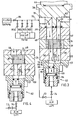
- the gear pump 20 has a front plate 22, a central plate 24 with a bore 30 + 32, a rear plate 26 and a motor housing 28.
- a driven or loose gear 34 which is rotatably mounted on a shaft 36
- the bore 30 receives a driven gear 38 which meshes with the loose gear 34 and is rotatably seated on a shaft 40.
- the driven shaft 40 is keyed onto a motor shaft 42 of a motor 44 placed on the motor housing 28, so that the motor can rotate the gear 38 and thus also the gear 34.
- an outlet chamber 48 In front of the area where the gears 34 and 38 interlock in the direction of rotation, there is an outlet chamber 48 in the plates 24 and 26 and after the area where the gears stop meshing, an inlet chamber 46 is provided in these plates.
- An O-ring 50 seals the shaft 40 on the back plate 26, while an O-ring 52 serves as a seal between the back plate 26 and the motor housing 28.
- each tooth fills as gears 34 and 38 rotate gap 54 with fluid material.
- the fluid material is conveyed along the inner walls of the bores 30 and 32 into the tooth spaces 54 until it reaches the outlet chamber 48, where the two gears 34, 38 comb the fluid material into the outlet chamber 48. Since the capacity of the tooth gaps is known and the speed of rotation of the gear wheels can be regulated, the pump can dose precise volumes essentially independently of changes in the viscosity, pressure and temperature of the fluid material.
- a first flushing channel 56 aligned with the inlet chamber 46 and a second flushing channel 58 aligned with the outlet chamber 48 extend through the front plate 22.
- a valve housing 63 connects to the front plate 22, in which the connecting channel 57 to the two Flushing channels 56, 58 is located, and in addition the valve housing 63 contains a pneumatically actuated valve 62 which has a piston 64 and a piston rod 66, with one end 68 of which the opening of the flushing channel 56 can be closed.
- the control valve 72 is opened so that the valve 62 clears a path through the side channel.
- the input 78 of the gear pump is connected via an inflow line 79 to the fluid material container of a selected color and one of the inflow valves 80a-d is opened, which then clears the way for the fluid material.
- Coating material then passes through the inlet chamber 46 to the gears 34 and 38 which convey it in the tooth spaces 54 between the teeth of the gears to the outlet chamber 48 and the outlet 82 and at the same time fluid material flows through the side channel to the outlet chamber for filling. This is in turn connected by a delivery line, not shown, to a paint spraying system, also not shown.
- the control valve 72 is closed, and the control valve 74 is opened.
- the piston 64 moves in the direction of the valve seat 76 until the end of the piston rod 66 closes it.
- the gear pump 20 conveys the fluid material from the inlet chamber 46 directly to the outlet chamber 48, from where it is then delivered to the paint spraying system.
- valve 62 is more advantageous than e.g. a slide valve. Only a single O-ring seal 86 is required to seal the valve against material in the channel, and the seal is never within the side channel. Therefore, the problem of sticking the valve due to the accumulation of fluid material in the area of the seal is eliminated. The valve always remains free to move. _
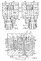
- FIG. 5 shows an embodiment of a valve 62 with automatic control and limitation of the maximum pressure that can occur at the outlet of the gear pump.
- the valve works in the same way as has already been explained in FIGS. 3 and 4.
- the valve 62 is provided to F-i gur 5 with a piston rod 88 which has a step 90 in the region of the connecting channel.
- the stage 90 is located in the connecting channel and forms a surface against which the pressure of the fluid material - as transmitted from the pump outlet through the flushing channel 58 - exerts a force that is proportional to the pressure and directed opposite to the force exerted on the piston 64 by the air introduced through the control valve 74.
- valve 62 In the arrangement of the valve 62 shown in FIG. 6, it is arranged so that the end of the piston rod 92 can close the flushing channel 58.
- the material pressure at the outlet from the gear pump exerts a force against the end of the piston rod that is proportional to the pressure and opposite to the force with which air enters through control valve 74, piston 64 and through the fluid material entering from the inlet the stage is loaded, whereby when sufficient pressure is generated at the outlet of the pump, the valve is moved in the direction in which the flushing channel is opened and a path between the outlet and the inlet of the pump is opened in order to limit the outlet pressure to a maximum value and Relieve overpressure condition.
- the maximum pressure developed by the pump can be automatically limited and controlled.
- the mechanical movement of the valve can be determined in response to an overpressure developed by the pump and a signal can be generated which warns an operator and informs of an error.
- valve housing 63 can be omitted and a valve located away from the pump can be connected via lines to the flushing channels 56 and 58.
- a valve between inlet 78 and outlet 82 of the gear pump can also be used for rapid flushing of the inlet and outlet lines, although this does not affect the flushing of the pump itself.
- the detergent introduced at the inlet 78 can simply be discharged to a spout or to a collection point after the rinsing channel 56, while at the same time other detergent is let into the rinsing channel 58, which leaves the gear pump again through the outlet.
- Figure 7 shows a gear pump, in which the gear 38 is pressed on the driven shaft 40 so that there is no gap between the two parts, in which the axis 36 is pressed stationary and also gap-free into the plate 26 and in which the loose gear 34 rotates about axis 36.
- an inlet fitting 94 is inserted for connection to a detergent source, not shown, to which a channel 96 connects, which extends in the plate to the bore for receiving the shaft 40.
- the shaft 40 includes an annular groove 98 which is permanently connected to the channel 96, a diametrical channel 100 which is connected at the ends to the annular groove 98, and an axial channel 102 which is located in the axis of the shaft 40 between the diametrical Channel 100 and an opposite end of this shaft is located.
- a channel 107 extends through the back plate 26 between the annular groove 98 and an annular groove 108 which surrounds the axis 36.
- a channel 109 runs diametrically through the axis 36 and is open at the ends to the annular groove 108. From this, a channel 110 branches off axially to the axis 36, which is connected at one point via a diametrical channel 111 and a further annular groove.
- the flushing agent entering the inlet fitting 94 also flows the channels 107, 109, 110, 111 and the annular groove 108 into the gap 112a between the gear 34 and the axis 36, in column 112b-c between the sides of the gear and the Pump body and in a space 114 between one end of the shaft and the pump body and from there into the tooth gaps 54 of the gear 34, from where it flows through the outlet of the gear pump, the entire driven part of the gear pump is completely cleaned of fluid material.
- the flushing agent admitted to inlet fitting 94 does not enter the gear pump through inlet 78, and the amount of flushing agent is less than when flushing agent is input at the inlet and a side channel is used.
- the pump and its inlet and outlet lines are combined with the embodiment of the invention shown in FIG. 7 with the embodiment in which a side channel is provided for the gear pump, or in another way in which a large volume flow of detergent through inlet and outlet chambers and corresponding lines can pass through.
- FIGS 8-10 show a further embodiment of the gear pump, which enables thorough cleaning of the entire pump interior if it is a gear pump in which the driving and driven shafts 36 and 40 each rotate within the pump body, and the driven and the driving Gear 34, 38 are attached to their associated shafts by pins 115 so that there are gaps between the shafts, the gears and the pump body.
- an inlet 116 in the motor housing is connected to a detergent source (not shown) and is connected via a channel 118 to a chamber 120 which is formed in the motor housing and the back plate 26 next to the shaft 40 and along it.
- a longitudinal spiral groove 122 which is connected to the chamber 120 at one end of the shaft, the arrangement being such that during the rotation of the shaft always part of the groove with the Chamber communicates.
- Another groove 124 is located in the surface of the shaft 36 and is connected to the motor housing 28 with the chamber 120 via a channel 126. The channel 126 is so large that the groove 124 remains in communication with it during the rotation of the shaft 36. Flushing agent introduced into inlet 116 therefore enters chamber 120 and grooves 122, 124 and then flows into and through all of the spaces between shafts 36 and 40 and the subsequent surfaces of the gears and pump body to clean them.
- a plurality of inlets 128a-d can also be connected to the detergent source and are located in the front plate 22 or rear plate 26, via associated channels 130a-d with corresponding semicircular grooves 132a-d. in connection.
- the detergent entering the inlets 128a-d therefore passes through the grooves 132a-d into the gap between the sides of the gears and the plates in order to clean them thoroughly.
- the flushing agent introduced into the gear pump at the inlets 116 and 128a-d finally reaches the tooth gaps 54 of the gear wheels 34 and 38, in order to flow out from there through the outlet of the gear pump.
- the detergent source can also be used two channels 134 and 136 are connected, which are connected to the inlet chamber 46 and the outlet chamber 48, respectively.
- the material inlet and outlet lines are open at their ends facing away from the gear pump, so that the flushing agent let into the channels through the chambers 46, 48, the inlet 78, the outlet 82 and the inlet or outlet lines to clean them thoroughly.
- the channels 134 and 136 can be optionally connected to one another via a bypass channel controlled by an installed or removed valve, so that the gear pump is flushed as previously described.
Landscapes
- Engineering & Computer Science (AREA)
- Mechanical Engineering (AREA)
- General Engineering & Computer Science (AREA)
- Rotary Pumps (AREA)
- Details And Applications Of Rotary Liquid Pumps (AREA)
- Coating Apparatus (AREA)
Applications Claiming Priority (2)
| Application Number | Priority Date | Filing Date | Title |
|---|---|---|---|
| US06/247,610 US4400147A (en) | 1981-03-25 | 1981-03-25 | Flushable rotary gear pump |
| US247610 | 2000-11-14 |
Publications (2)
| Publication Number | Publication Date |
|---|---|
| EP0061630A1 true EP0061630A1 (fr) | 1982-10-06 |
| EP0061630B1 EP0061630B1 (fr) | 1985-06-19 |
Family
ID=22935577
Family Applications (1)
| Application Number | Title | Priority Date | Filing Date |
|---|---|---|---|
| EP82102036A Expired EP0061630B1 (fr) | 1981-03-23 | 1982-03-13 | Pompe à engrenage à dispositif pour nettoyer |
Country Status (6)
| Country | Link |
|---|---|
| US (1) | US4400147A (fr) |
| EP (1) | EP0061630B1 (fr) |
| JP (1) | JPS57165685A (fr) |
| CA (1) | CA1174113A (fr) |
| DE (1) | DE3264206D1 (fr) |
| ES (2) | ES8308398A1 (fr) |
Cited By (9)
| Publication number | Priority date | Publication date | Assignee | Title |
|---|---|---|---|---|
| DE4425227A1 (de) * | 1994-07-16 | 1996-01-18 | Abb Patent Gmbh | Zahnradpumpe zur Lackförderung |
| DE4425226A1 (de) * | 1994-07-16 | 1996-01-18 | Abb Patent Gmbh | Zahnradpumpe zur Lackförderung |
| FR2729437A1 (fr) * | 1995-01-17 | 1996-07-19 | Kodak Pathe | Pompe a dispositif de nettoyage en place |
| EP0799997A1 (fr) * | 1996-04-04 | 1997-10-08 | CATTA 27 S.r.l. | Pompe hydraulique pour produits alimentaires |
| GB2326833A (en) * | 1997-07-01 | 1999-01-06 | Honda Motor Co Ltd | Plural color painting apparatus |
| EP0939226A1 (fr) * | 1998-02-26 | 1999-09-01 | Ahlstrom Paper Group OY | Pompe à déplacement et son procédé d'utilisation |
| DE10202618C1 (de) * | 2001-12-12 | 2003-04-03 | Kreyenborg Verwaltungen | Förderpumpe für fluide Medien |
| EP1164293A3 (fr) * | 2000-06-14 | 2003-06-04 | Barmag AG | Pompe à engrenages avec dispositif pour nettoyage |
| US6802702B2 (en) | 2001-12-12 | 2004-10-12 | Kreyenborg Verwal Tungen Und Beteiligungen Gmbh & Co. Kg | Feed pump for fluidic media having sleeve bearing lubrication |
Families Citing this family (22)
| Publication number | Priority date | Publication date | Assignee | Title |
|---|---|---|---|---|
| US4534717A (en) * | 1981-05-01 | 1985-08-13 | Ford Motor Company | Flushable metering pump |
| JPS6053815A (ja) * | 1983-09-02 | 1985-03-27 | Oval Eng Co Ltd | 定置洗浄流量計 |
| US4792292A (en) * | 1987-09-25 | 1988-12-20 | Tampo-Tool, Inc. | Ink pump system |
| JPH0730943Y2 (ja) * | 1988-05-12 | 1995-07-19 | 旭サナック株式会社 | 外装塗装装置 |
| US4953403A (en) * | 1989-03-15 | 1990-09-04 | Binks Manufacturing Company | Positive displacement flushable flow meter |
| DE4040409C1 (fr) * | 1990-12-18 | 1992-05-14 | Vse Schweisstechnik Gmbh, 5982 Neuenrade, De | |
| DE4100724A1 (de) * | 1991-01-10 | 1992-07-16 | Vogel Willi Ag | Zentralschmieraggregat |
| US6241016B1 (en) * | 1998-04-03 | 2001-06-05 | R & M Energy Systems | Drive head assembly |
| US6205779B1 (en) * | 1999-03-31 | 2001-03-27 | Daimlerchrysler Corporation | Integral hub driven gears |
| US20030079786A1 (en) * | 2001-10-30 | 2003-05-01 | Diana Michael J. | Modular fluid pressure regulator with bypass |
| US6702701B2 (en) | 2001-12-28 | 2004-03-09 | Visteon Global Technologies, Inc. | Oil pump with integral fast acting valve for controlling planetary system torque |
| US6808121B2 (en) * | 2003-02-11 | 2004-10-26 | Charles J. Rice | Fluid pump |
| US20070201989A1 (en) * | 2005-10-14 | 2007-08-30 | Parker-Hannifin | Low ripple gear pump/motor |
| DE102006022570A1 (de) * | 2006-05-15 | 2007-11-29 | Dürr Systems GmbH | Beschichtungseinrichtung und zugehöriges Betriebsverfahren |
| CN101657643B (zh) * | 2007-03-20 | 2012-12-26 | 欧瑞康纺织有限及两合公司 | 齿轮泵 |
| DE502008001091D1 (de) * | 2007-05-03 | 2010-09-16 | Oerlikon Textile Gmbh & Co Kg | Zahnradpumpe |
| US8225968B2 (en) * | 2009-05-12 | 2012-07-24 | Illinois Tool Works Inc. | Seal system for gear pumps |
| US9249789B2 (en) | 2010-10-08 | 2016-02-02 | Ravindra Kashyap | Pipe pump system |
| DE102013003620B4 (de) * | 2013-02-18 | 2016-02-04 | Dürr Systems GmbH | Beschichtungsmittelpumpe und Reinigungsverfahren für eine Beschichtungsmittelpumpe |
| JP1546565S (fr) * | 2015-08-19 | 2016-03-28 | ||
| DE102019101455A1 (de) | 2019-01-21 | 2020-07-23 | Hnp Mikrosysteme Gmbh | Selbstspülende Mikropumpe |
| CN110425130A (zh) * | 2019-08-09 | 2019-11-08 | 天津铭捷智能装备有限公司 | 一种齿轮泵 |
Citations (1)
| Publication number | Priority date | Publication date | Assignee | Title |
|---|---|---|---|---|
| US3870233A (en) * | 1973-09-12 | 1975-03-11 | Nordson Corp | Color change of electrostatic spray apparatus |
Family Cites Families (4)
| Publication number | Priority date | Publication date | Assignee | Title |
|---|---|---|---|---|
| US2808004A (en) * | 1952-02-19 | 1957-10-01 | John D Durant | Pumping mechanism |
| US3130673A (en) * | 1961-08-01 | 1964-04-28 | Arthur K Finstad | Rotary vane pump with replaceable head unit |
| US3806283A (en) * | 1973-01-04 | 1974-04-23 | Int Standard Electric Corp | Pump by-pass |
| US4073605A (en) * | 1976-09-15 | 1978-02-14 | Crepaco, Inc. | Rotary pump construction with cleaning feature |
-
1981
- 1981-03-25 US US06/247,610 patent/US4400147A/en not_active Expired - Fee Related
-
1982
- 1982-03-13 DE DE8282102036T patent/DE3264206D1/de not_active Expired
- 1982-03-13 EP EP82102036A patent/EP0061630B1/fr not_active Expired
- 1982-03-19 JP JP57042995A patent/JPS57165685A/ja active Pending
- 1982-03-22 ES ES82510637A patent/ES8308398A1/es not_active Expired
- 1982-03-23 CA CA000399157A patent/CA1174113A/fr not_active Expired
-
1983
- 1983-03-30 ES ES83521173A patent/ES8406652A1/es not_active Expired
Patent Citations (1)
| Publication number | Priority date | Publication date | Assignee | Title |
|---|---|---|---|---|
| US3870233A (en) * | 1973-09-12 | 1975-03-11 | Nordson Corp | Color change of electrostatic spray apparatus |
Cited By (14)
| Publication number | Priority date | Publication date | Assignee | Title |
|---|---|---|---|---|
| DE4425226A1 (de) * | 1994-07-16 | 1996-01-18 | Abb Patent Gmbh | Zahnradpumpe zur Lackförderung |
| EP0696680A1 (fr) * | 1994-07-16 | 1996-02-14 | ABBPATENT GmbH | Pompe à engrenages pour le refoulement de laque |
| EP0696679A1 (fr) * | 1994-07-16 | 1996-02-14 | ABBPATENT GmbH | Pompe à engrenages pour le refoulement de laque |
| DE4425227A1 (de) * | 1994-07-16 | 1996-01-18 | Abb Patent Gmbh | Zahnradpumpe zur Lackförderung |
| FR2729437A1 (fr) * | 1995-01-17 | 1996-07-19 | Kodak Pathe | Pompe a dispositif de nettoyage en place |
| US5904474A (en) * | 1996-04-04 | 1999-05-18 | Catta 27 S.R.L. | Hydraulic pump, suitable for food products |
| EP0799997A1 (fr) * | 1996-04-04 | 1997-10-08 | CATTA 27 S.r.l. | Pompe hydraulique pour produits alimentaires |
| GB2326833A (en) * | 1997-07-01 | 1999-01-06 | Honda Motor Co Ltd | Plural color painting apparatus |
| US6050498A (en) * | 1997-07-01 | 2000-04-18 | Honda Giken Kogyo Kabushiki Kaisha | Multiple color painting apparatus |
| GB2326833B (en) * | 1997-07-01 | 2001-04-04 | Honda Motor Co Ltd | Plural color painting apparatus |
| EP0939226A1 (fr) * | 1998-02-26 | 1999-09-01 | Ahlstrom Paper Group OY | Pompe à déplacement et son procédé d'utilisation |
| EP1164293A3 (fr) * | 2000-06-14 | 2003-06-04 | Barmag AG | Pompe à engrenages avec dispositif pour nettoyage |
| DE10202618C1 (de) * | 2001-12-12 | 2003-04-03 | Kreyenborg Verwaltungen | Förderpumpe für fluide Medien |
| US6802702B2 (en) | 2001-12-12 | 2004-10-12 | Kreyenborg Verwal Tungen Und Beteiligungen Gmbh & Co. Kg | Feed pump for fluidic media having sleeve bearing lubrication |
Also Published As
| Publication number | Publication date |
|---|---|
| EP0061630B1 (fr) | 1985-06-19 |
| CA1174113A (fr) | 1984-09-11 |
| ES521173A0 (es) | 1984-07-01 |
| ES8406652A1 (es) | 1984-07-01 |
| ES510637A0 (es) | 1983-09-01 |
| US4400147A (en) | 1983-08-23 |
| ES8308398A1 (es) | 1983-09-01 |
| JPS57165685A (en) | 1982-10-12 |
| DE3264206D1 (en) | 1985-07-25 |
Similar Documents
| Publication | Publication Date | Title |
|---|---|---|
| EP0061630B1 (fr) | Pompe à engrenage à dispositif pour nettoyer | |
| DE69001744T2 (de) | Anlage zum elektrostatischen Auftragen eines leitfähigen Beschichtungsproduktes. | |
| DE2339954C2 (de) | Zahnradpumpe | |
| DE1504699B1 (de) | Vorrichtung zum Mischen und Austragen von Stoffen fuer die Herstellung von Polyurethanschaum | |
| DE3410302C2 (de) | Vorrichtung zum Abfüllen dosierter Mengen einer flüssigen bis zähflüssigen Subsstanz, insbesondere Schokoladenmasse | |
| DE3630077A1 (de) | Vorrichtung zum gleichzeitigen dosierten abfuellen von fluessigen oder weichplastischen stoffen, wie butter, margarine, pasten oder dgl. ueber mundstuecke in benachbart zueinander angeordnete behaelter | |
| DE4104647A1 (de) | Mischvorrichtung zur verarbeitung fluessiger mehrkomponenten-kunststoffe, insbesondere polyurethan | |
| EP1631434A1 (fr) | Dispositif pour preparer des substances | |
| DE69412813T2 (de) | Radauftragsgerät zum auftragen von klebstoff, insbesondere auf buchrücken beim buchbinden | |
| EP0612659A1 (fr) | Dispositif pour introduire un matériau dans une chambre | |
| EP1395490B1 (fr) | Dispositif de dosage installe dans une machine servant a remplir des tubes | |
| DE10213270A1 (de) | Beschichtungsanlage mit einem Zerstäuber und einer Dosierpumpe | |
| DE4031649C2 (de) | Dosier- und Mischanlage | |
| DE69208461T2 (de) | Gerät zum Abgeben einer definierten Flüssigkeitsmenge | |
| DE10235102B4 (de) | Lackiereinrichtung mit einer molchbaren Ventileinrichtung | |
| DE4445946C2 (de) | Vorrichtung zum Zuführen der Einzelkomponenten von flüssigem Mehrkomponenten-Kunststoff an eine Ausgußdüse | |
| EP0696680B1 (fr) | Pompe à engrenages pour le refoulement de laque | |
| DE3630992C2 (de) | Vorrichtung zum Dosieren und Mischen von Stoffen | |
| DE3026788C2 (de) | Dichtungsanordnung | |
| EP0356635A2 (fr) | Dispositif d'évacuation | |
| EP1252936B1 (fr) | Cylindre pour un système de revêtement et méthode d'utilisation | |
| EP0735307B1 (fr) | Procédé et dispositif pour étancher une conduite et/ou la jonction d'un branchement latéral | |
| EP0093356B1 (fr) | Dispositif mélangeur pour matières plastiques à composants multiples | |
| DE69206577T2 (de) | Vorrichtung zum Dosieren hochviskoser Substanzen. | |
| DE2248235C2 (de) | Vorrichtung zum Austragen von Schaummassen und ähnlichen empfindlichen Massen in Teilmengen |
Legal Events
| Date | Code | Title | Description |
|---|---|---|---|
| PUAI | Public reference made under article 153(3) epc to a published international application that has entered the european phase |
Free format text: ORIGINAL CODE: 0009012 |
|
| 17P | Request for examination filed |
Effective date: 19820315 |
|
| AK | Designated contracting states |
Designated state(s): BE DE FR GB IT NL SE |
|
| ITF | It: translation for a ep patent filed | ||
| GRAA | (expected) grant |
Free format text: ORIGINAL CODE: 0009210 |
|
| AK | Designated contracting states |
Designated state(s): BE DE FR GB IT NL SE |
|
| REF | Corresponds to: |
Ref document number: 3264206 Country of ref document: DE Date of ref document: 19850725 |
|
| ET | Fr: translation filed | ||
| PLBI | Opposition filed |
Free format text: ORIGINAL CODE: 0009260 |
|
| 26 | Opposition filed |
Opponent name: BARMAG BARMER MASCHINENFABRIK AG Effective date: 19860315 |
|
| NLR1 | Nl: opposition has been filed with the epo |
Opponent name: BARMAG BARMER MASCHINENFABRIK AG |
|
| PGFP | Annual fee paid to national office [announced via postgrant information from national office to epo] |
Ref country code: NL Payment date: 19870331 Year of fee payment: 6 |
|
| RDAG | Patent revoked |
Free format text: ORIGINAL CODE: 0009271 |
|
| STAA | Information on the status of an ep patent application or granted ep patent |
Free format text: STATUS: PATENT REVOKED |
|
| 27W | Patent revoked |
Effective date: 19870823 |
|
| GBPR | Gb: patent revoked under art. 102 of the ep convention designating the uk as contracting state | ||
| NLR2 | Nl: decision of opposition | ||
| BERE | Be: lapsed |
Owner name: BINKS MFG CY Effective date: 19880331 Owner name: BAYER A.G. Effective date: 19880331 |
|
| EUG | Se: european patent has lapsed |
Ref document number: 82102036.9 Effective date: 19881205 |