EP0061864A1 - Systeme zum Feststellen der Luftgeschwindigkeit - Google Patents
Systeme zum Feststellen der Luftgeschwindigkeit Download PDFInfo
- Publication number
- EP0061864A1 EP0061864A1 EP82301344A EP82301344A EP0061864A1 EP 0061864 A1 EP0061864 A1 EP 0061864A1 EP 82301344 A EP82301344 A EP 82301344A EP 82301344 A EP82301344 A EP 82301344A EP 0061864 A1 EP0061864 A1 EP 0061864A1
- Authority
- EP
- European Patent Office
- Prior art keywords
- airspeed
- portions
- sensing system
- tube
- airspeed sensing
- Prior art date
- Legal status (The legal status is an assumption and is not a legal conclusion. Google has not performed a legal analysis and makes no representation as to the accuracy of the status listed.)
- Granted
Links
- 230000004888 barrier function Effects 0.000 claims abstract description 10
- 238000005259 measurement Methods 0.000 claims description 4
- 238000009529 body temperature measurement Methods 0.000 claims 1
- 230000000694 effects Effects 0.000 description 8
- 230000003068 static effect Effects 0.000 description 5
- 230000002776 aggregation Effects 0.000 description 1
- 238000004220 aggregation Methods 0.000 description 1
- 238000009530 blood pressure measurement Methods 0.000 description 1
- 238000012937 correction Methods 0.000 description 1
- 238000000034 method Methods 0.000 description 1
- 239000002245 particle Substances 0.000 description 1
- 239000007787 solid Substances 0.000 description 1
Images
Classifications
-
- G—PHYSICS
- G01—MEASURING; TESTING
- G01F—MEASURING VOLUME, VOLUME FLOW, MASS FLOW OR LIQUID LEVEL; METERING BY VOLUME
- G01F1/00—Measuring the volume flow or mass flow of fluid or fluent solid material wherein the fluid passes through a meter in a continuous flow
- G01F1/05—Measuring the volume flow or mass flow of fluid or fluent solid material wherein the fluid passes through a meter in a continuous flow by using mechanical effects
- G01F1/34—Measuring the volume flow or mass flow of fluid or fluent solid material wherein the fluid passes through a meter in a continuous flow by using mechanical effects by measuring pressure or differential pressure
- G01F1/36—Measuring the volume flow or mass flow of fluid or fluent solid material wherein the fluid passes through a meter in a continuous flow by using mechanical effects by measuring pressure or differential pressure the pressure or differential pressure being created by the use of flow constriction
- G01F1/38—Measuring the volume flow or mass flow of fluid or fluent solid material wherein the fluid passes through a meter in a continuous flow by using mechanical effects by measuring pressure or differential pressure the pressure or differential pressure being created by the use of flow constriction the pressure or differential pressure being measured by means of a movable element, e.g. diaphragm, piston, Bourdon tube or flexible capsule
-
- G—PHYSICS
- G01—MEASURING; TESTING
- G01P—MEASURING LINEAR OR ANGULAR SPEED, ACCELERATION, DECELERATION, OR SHOCK; INDICATING PRESENCE, ABSENCE, OR DIRECTION, OF MOVEMENT
- G01P5/00—Measuring speed of fluids, e.g. of air stream; Measuring speed of bodies relative to fluids, e.g. of ship, of aircraft
- G01P5/14—Measuring speed of fluids, e.g. of air stream; Measuring speed of bodies relative to fluids, e.g. of ship, of aircraft by measuring differences of pressure in the fluid
Definitions
- an airspeed sensing system comprising:
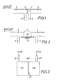
- the tube arrangement may comprise a single straight tube closed by a central barrier which divides the tube into said first and second portions, or two separate tubes preferably aligned with one another.
- first and second side branches are connected to said first and second portions respectively, and the airspeed indication is obtained in dependence on measurements of the pressures in said first and second portions and derived through said first and second side branches.
- the first embodiment of airspeed sensing system comprises a tube arrangement formed by a straight circular cylindrical tube 1 which is open at both ends and closed at the centre by a barrier 2 so as to form a first open-ended portion 3 and a second open-ended portion 4.
- the tube arrangement is end-for-end symmetrical and in use the open end of the portion 3 is arranged to face substantially directly into an airflow, so that the portion 4 is facing in substantially the opposite direction to the airflow.
- Side branches 5 and 6 are connected to the portions 3 and 4 respectively and lead to a pressure transducer arrangement for deriving an airspeed indication in dependence on the pressures in the portions 3 and 4.
- a controlled leak in the form of an aperture 7 in the barrier 2 and of small diameter relative to the diameter of the tube 1 provides a restricted passage through which a fraction of the air entering the portion 3 can leak to the portion 4. The effect of this leakage of air is to counteract the drag effect which would otherwise reduce the static pressure measurement obtained from the portion 4, and results in a "psuedostatic" pressure in the portion 4.
- this psuedostatic pressure S' is used in place of the static pressure S in the formula given above, while the pitot pressure P is derived from the portion 3 in the usual way.
- this arrangement has a high common mode rejection and when the tube 1 is end-for-end symmetrical the response is bi-directional. Thus an indication can be obtained when the portion 4 is facing into the airflow and in this case leakage of air through the aperture 7 is in the opposite direction.
- embodiments of the invention are particularly suitable for use on vehicles such as helicopters, VTOL aircraft and hovercraft.
Landscapes
- Physics & Mathematics (AREA)
- General Physics & Mathematics (AREA)
- Engineering & Computer Science (AREA)
- Aviation & Aerospace Engineering (AREA)
- Fluid Mechanics (AREA)
- Measuring Fluid Pressure (AREA)
- Indicating Or Recording The Presence, Absence, Or Direction Of Movement (AREA)
- Measuring Temperature Or Quantity Of Heat (AREA)
Applications Claiming Priority (2)
| Application Number | Priority Date | Filing Date | Title |
|---|---|---|---|
| GB8109242 | 1981-03-24 | ||
| GB8109242 | 1981-03-24 |
Publications (2)
| Publication Number | Publication Date |
|---|---|
| EP0061864A1 true EP0061864A1 (de) | 1982-10-06 |
| EP0061864B1 EP0061864B1 (de) | 1986-01-29 |
Family
ID=10520627
Family Applications (1)
| Application Number | Title | Priority Date | Filing Date |
|---|---|---|---|
| EP82301344A Expired EP0061864B1 (de) | 1981-03-24 | 1982-03-16 | Systeme zum Feststellen der Luftgeschwindigkeit |
Country Status (3)
| Country | Link |
|---|---|
| US (1) | US4437343A (de) |
| EP (1) | EP0061864B1 (de) |
| DE (1) | DE3268742D1 (de) |
Cited By (1)
| Publication number | Priority date | Publication date | Assignee | Title |
|---|---|---|---|---|
| EP0335040A3 (en) * | 1988-03-30 | 1990-08-01 | Leroy Dry Ginn | Variable gas volume flow measuring and control methods and apparatus |
Families Citing this family (5)
| Publication number | Priority date | Publication date | Assignee | Title |
|---|---|---|---|---|
| US4843880A (en) * | 1985-01-14 | 1989-07-04 | Roland Sommer | Method for measuring the direction and force of gaseous or liquid flows and probe for carrying out this method |
| US6101429A (en) * | 1998-04-07 | 2000-08-08 | Tao Of Systems Integration, Inc. | Broad-range, multi-directional aircraft airspeed measuring system |
| FR2833347B1 (fr) * | 2001-12-11 | 2004-02-27 | Thales Sa | Sonde multifonction pour aeronef |
| US7185538B2 (en) * | 2004-11-12 | 2007-03-06 | Honeywell International Inc. | Methods and systems for sensing air vehicle airspeed |
| CN116068221B (zh) * | 2023-03-06 | 2023-06-06 | 中国空气动力研究与发展中心空天技术研究所 | 一种可防水的空速测量装置 |
Citations (5)
| Publication number | Priority date | Publication date | Assignee | Title |
|---|---|---|---|---|
| DE442293C (de) * | 1925-03-10 | 1927-03-28 | Askania Werke A G Vorm Central | Sicherheitsabschlussorgan fuer Differenzdruckmesser, bei welchem die nach dem Differenzdruckmesser fuehrenden Druckleitungen mit einer Kurzschlussvorrichtung versehen sind |
| US2487414A (en) * | 1947-12-15 | 1949-11-08 | Adrian A Baxter | Wind gauge |
| DE1100995B (de) * | 1958-12-05 | 1961-03-02 | Heinrich Dietz Ind Elektronik | Vorrichtung zur Ermittlung der Durchfluss- und Gesamtmengen stroemender Medien |
| US3822592A (en) * | 1973-03-29 | 1974-07-09 | Fischer & Porter Co | Integral orifice assembly for head meters |
| GB2011626A (en) * | 1977-12-16 | 1979-07-11 | Grande Per Olof | Flow meter |
Family Cites Families (1)
| Publication number | Priority date | Publication date | Assignee | Title |
|---|---|---|---|---|
| US2585290A (en) | 1948-12-27 | 1952-02-12 | Harold M Northcutt | Orifice plate fitting |
-
1982
- 1982-03-16 EP EP82301344A patent/EP0061864B1/de not_active Expired
- 1982-03-16 DE DE8282301344T patent/DE3268742D1/de not_active Expired
- 1982-03-19 US US06/359,800 patent/US4437343A/en not_active Expired - Lifetime
Patent Citations (5)
| Publication number | Priority date | Publication date | Assignee | Title |
|---|---|---|---|---|
| DE442293C (de) * | 1925-03-10 | 1927-03-28 | Askania Werke A G Vorm Central | Sicherheitsabschlussorgan fuer Differenzdruckmesser, bei welchem die nach dem Differenzdruckmesser fuehrenden Druckleitungen mit einer Kurzschlussvorrichtung versehen sind |
| US2487414A (en) * | 1947-12-15 | 1949-11-08 | Adrian A Baxter | Wind gauge |
| DE1100995B (de) * | 1958-12-05 | 1961-03-02 | Heinrich Dietz Ind Elektronik | Vorrichtung zur Ermittlung der Durchfluss- und Gesamtmengen stroemender Medien |
| US3822592A (en) * | 1973-03-29 | 1974-07-09 | Fischer & Porter Co | Integral orifice assembly for head meters |
| GB2011626A (en) * | 1977-12-16 | 1979-07-11 | Grande Per Olof | Flow meter |
Cited By (1)
| Publication number | Priority date | Publication date | Assignee | Title |
|---|---|---|---|---|
| EP0335040A3 (en) * | 1988-03-30 | 1990-08-01 | Leroy Dry Ginn | Variable gas volume flow measuring and control methods and apparatus |
Also Published As
| Publication number | Publication date |
|---|---|
| EP0061864B1 (de) | 1986-01-29 |
| US4437343A (en) | 1984-03-20 |
| DE3268742D1 (en) | 1986-03-13 |
Similar Documents
| Publication | Publication Date | Title |
|---|---|---|
| US4096744A (en) | Pressure sensor for determining airspeed, altitude and angle of attack | |
| US4378696A (en) | Pressure sensor for determining airspeed altitude and angle of attack | |
| EP0287223B1 (de) | Vorrichtung zum Messen von Luftdaten | |
| US4378697A (en) | Strut mounted multiple static tube | |
| EP0719416B1 (de) | Integrierbarer tragflächenmessaufnehmer für die gesamttemperatur | |
| US3482445A (en) | Strut mounted dual static tube | |
| US2662402A (en) | Flight test head | |
| EP0167585A4 (de) | Druckempfindliches fühlerinstrument für luftfahrzeug. | |
| JPS62159023A (ja) | 気流デ−タ検出用のプロ−ブ | |
| US11566892B2 (en) | Air data probe | |
| US4672846A (en) | Multi-function pressure probe for aircraft | |
| US6101429A (en) | Broad-range, multi-directional aircraft airspeed measuring system | |
| EP0061864B1 (de) | Systeme zum Feststellen der Luftgeschwindigkeit | |
| US7127335B2 (en) | Low airspeed assist algorithm for air data computer applications | |
| US3400584A (en) | Airspeed indicating apparatus | |
| US2493931A (en) | True air-speed meter | |
| US3149491A (en) | Airborne jet stream detector | |
| US2725746A (en) | Composite sensing head and control unit | |
| US4061028A (en) | Aircraft total energy sensor | |
| US3347095A (en) | Atmospheric static pressure detection means | |
| US4572004A (en) | Fluid flow meter for measuring the rate of fluid flow in a conduit | |
| US1929091A (en) | Rate of climb instruments | |
| US2596116A (en) | Airplane pressure differential stall indicator | |
| US2986033A (en) | Angle of attack instrumentation for aircraft | |
| US4448069A (en) | Airspeed sensing post for determining relative velocity of a fluid and a carrier |
Legal Events
| Date | Code | Title | Description |
|---|---|---|---|
| PUAI | Public reference made under article 153(3) epc to a published international application that has entered the european phase |
Free format text: ORIGINAL CODE: 0009012 |
|
| AK | Designated contracting states |
Designated state(s): DE FR GB IT |
|
| 17P | Request for examination filed |
Effective date: 19830406 |
|
| ITF | It: translation for a ep patent filed | ||
| GRAA | (expected) grant |
Free format text: ORIGINAL CODE: 0009210 |
|
| AK | Designated contracting states |
Designated state(s): DE FR GB IT |
|
| REF | Corresponds to: |
Ref document number: 3268742 Country of ref document: DE Date of ref document: 19860313 |
|
| ET | Fr: translation filed | ||
| PLBE | No opposition filed within time limit |
Free format text: ORIGINAL CODE: 0009261 |
|
| STAA | Information on the status of an ep patent application or granted ep patent |
Free format text: STATUS: NO OPPOSITION FILED WITHIN TIME LIMIT |
|
| 26N | No opposition filed | ||
| ITTA | It: last paid annual fee | ||
| PGFP | Annual fee paid to national office [announced via postgrant information from national office to epo] |
Ref country code: DE Payment date: 19890426 Year of fee payment: 8 |
|
| PG25 | Lapsed in a contracting state [announced via postgrant information from national office to epo] |
Ref country code: DE Effective date: 19901201 |
|
| PGFP | Annual fee paid to national office [announced via postgrant information from national office to epo] |
Ref country code: GB Payment date: 19970317 Year of fee payment: 16 |
|
| PGFP | Annual fee paid to national office [announced via postgrant information from national office to epo] |
Ref country code: FR Payment date: 19970325 Year of fee payment: 16 |
|
| PG25 | Lapsed in a contracting state [announced via postgrant information from national office to epo] |
Ref country code: GB Free format text: LAPSE BECAUSE OF NON-PAYMENT OF DUE FEES Effective date: 19980316 |
|
| PG25 | Lapsed in a contracting state [announced via postgrant information from national office to epo] |
Ref country code: FR Free format text: THE PATENT HAS BEEN ANNULLED BY A DECISION OF A NATIONAL AUTHORITY Effective date: 19980331 |
|
| GBPC | Gb: european patent ceased through non-payment of renewal fee |
Effective date: 19980316 |
|
| REG | Reference to a national code |
Ref country code: FR Ref legal event code: ST |