EP0061937B1 - Tête détectrice photoélectrique réglable pour interrupteur à valeur limite à état solide - Google Patents
Tête détectrice photoélectrique réglable pour interrupteur à valeur limite à état solide Download PDFInfo
- Publication number
- EP0061937B1 EP0061937B1 EP82301709A EP82301709A EP0061937B1 EP 0061937 B1 EP0061937 B1 EP 0061937B1 EP 82301709 A EP82301709 A EP 82301709A EP 82301709 A EP82301709 A EP 82301709A EP 0061937 B1 EP0061937 B1 EP 0061937B1
- Authority
- EP
- European Patent Office
- Prior art keywords
- housing
- cradle
- detector head
- window
- photoelectric detector
- Prior art date
- Legal status (The legal status is an assumption and is not a legal conclusion. Google has not performed a legal analysis and makes no representation as to the accuracy of the status listed.)
- Expired
Links
- 239000007787 solid Substances 0.000 title claims description 9
- 230000006835 compression Effects 0.000 claims description 2
- 238000007906 compression Methods 0.000 claims description 2
- 239000012530 fluid Substances 0.000 claims 1
- 238000007789 sealing Methods 0.000 claims 1
- 230000011514 reflex Effects 0.000 description 4
- 239000000356 contaminant Substances 0.000 description 3
- 238000001514 detection method Methods 0.000 description 3
- 238000011109 contamination Methods 0.000 description 2
- 230000035945 sensitivity Effects 0.000 description 2
- 239000004593 Epoxy Substances 0.000 description 1
- 239000004020 conductor Substances 0.000 description 1
- 230000007423 decrease Effects 0.000 description 1
- 230000007812 deficiency Effects 0.000 description 1
- -1 dirt Substances 0.000 description 1
- 238000006073 displacement reaction Methods 0.000 description 1
- 239000000428 dust Substances 0.000 description 1
- 230000007613 environmental effect Effects 0.000 description 1
- 238000005286 illumination Methods 0.000 description 1
- 239000002184 metal Substances 0.000 description 1
- 238000000034 method Methods 0.000 description 1
- 238000012986 modification Methods 0.000 description 1
- 230000004048 modification Effects 0.000 description 1
- 239000011295 pitch Substances 0.000 description 1
- 239000000779 smoke Substances 0.000 description 1
Images



Classifications
-
- G—PHYSICS
- G01—MEASURING; TESTING
- G01S—RADIO DIRECTION-FINDING; RADIO NAVIGATION; DETERMINING DISTANCE OR VELOCITY BY USE OF RADIO WAVES; LOCATING OR PRESENCE-DETECTING BY USE OF THE REFLECTION OR RERADIATION OF RADIO WAVES; ANALOGOUS ARRANGEMENTS USING OTHER WAVES
- G01S17/00—Systems using the reflection or reradiation of electromagnetic waves other than radio waves, e.g. lidar systems
- G01S17/02—Systems using the reflection of electromagnetic waves other than radio waves
- G01S17/06—Systems determining position data of a target
- G01S17/46—Indirect determination of position data
- G01S17/48—Active triangulation systems, i.e. using the transmission and reflection of electromagnetic waves other than radio waves
-
- G—PHYSICS
- G01—MEASURING; TESTING
- G01C—MEASURING DISTANCES, LEVELS OR BEARINGS; SURVEYING; NAVIGATION; GYROSCOPIC INSTRUMENTS; PHOTOGRAMMETRY OR VIDEOGRAMMETRY
- G01C3/00—Measuring distances in line of sight; Optical rangefinders
- G01C3/10—Measuring distances in line of sight; Optical rangefinders using a parallactic triangle with variable angles and a base of fixed length in the observation station, e.g. in the instrument
-
- G—PHYSICS
- G01—MEASURING; TESTING
- G01V—GEOPHYSICS; GRAVITATIONAL MEASUREMENTS; DETECTING MASSES OR OBJECTS; TAGS
- G01V8/00—Prospecting or detecting by optical means
- G01V8/10—Detecting, e.g. by using light barriers
- G01V8/12—Detecting, e.g. by using light barriers using one transmitter and one receiver
Definitions
- This invention relates to photoelectric switches used to detect the presence or absence of an object. More particularly the invention relates to diffuse reflective type photoelectric switches wherein the light source and the detector are on the same side of the object. Specifically the invention relates to switches of the aforementioned type which are suited for use in an industrial environment of atmospheric contamination.
- switches be adjustable to provide a strong light signal to maintain good operational reliability under environmental contamination, but to preclude nuisance signals from background surfaces caused by the strong light signal.
- a preferred method of adjustment is to vary the angle of convergence between the source beam and the detector beam wherein the two beams intersect at the surface of the object to be detected. Such adjustment should be simple, readily accessible yet protected from unintentional adjustment and from the environment, and should preferably include an indication of the adjustment.
- French Application FR-A-2429442 discloses a photoelectric detector head comprising:
- An embodiment of this invention provides a photoelectric detector head for a solid state limit switch which is adjustable to provide a strong operating signal at a range of detection distances, which has an indication of the adjustment of the head, and which is enclosed to seal out atmospheric contaminants and to protect the adjustment and indication means.
- Figure 1 shows the photoelectric detector head 2 of this invention assembled to a solid state limit switch 4, the enclosure of which is like those described in United States Patent Nos. 3,983,343; 3,882,290; 3,819,888 and 3,793,492.
- Limit switch 4 includes a base receptacle 6 which may be firmly attached and hard-wired to a machine or other apparatus.
- a cover or body unit 8 is secured to the receptacle 6 by a pair of screws 10.
- the body unit 8 houses a solid state switch such as that disclosed in United States Patent No. 4,199,694.
- Cooperating plug-in terminals in the body unit 8 and receptacle 6 connect the switch to the source and apparatus control wires connected to the receptacle 6.
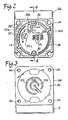
- Body unit 8 also includes a mounting flange 8a for the detector head 2, the flange 8a being provided with four tapped openings 8b (Fig. 3) for. receiving detector head mounting screws 12 which pass through cooperating openings in the head 2. It will be noted that the openings 8b are arranged in a square pattern to permit the mounting of head 2 on flange 8a in any of four major axis positions.
- the disclosures of the aforementioned patents are hereby incorporated in this application by reference.
- Detector head 2 comprises a hollow molded case 14 having an opening 14a in one side wall and a bottom opening 14b.
- a pair of grooves 14c and 14d, open to the bottom opening 14b, are formed in opposed interior sidewalls of case 14 near another side thereof to serve as retainers for the edges of a printed circuit board assembly 16.
- the latter assembly includes a hybrid integrated circuit 18, a light emitting diode, or LED, 20 and three contact springs 22.
- Other components incidental to the circuitry but not critical to an understanding of the invention are also mounted on the printed circuit board, but are not shown on the drawing for the sake of clarity. As seen in Fig.
- the contact springs 22 are mechanically fastened to printed circuit board 16 by riveting or the like and are formed over the edge of the board adjacent bottom opening 14b to project across opening 14b.
- the free ends of contact springs 22 are formed with a first reflex bend to extend back toward the center of the opening 14b and then terminate in downwardly or outwardly formed, bifurcated reflex contact portions 22a.
- Case 14 has a cylindrical bore 14e which is open to the opening 14b.
- a helical compression spring 24 is inserted in the bore 14e, the relaxed length of spring 24 being greater than the depth of bore 14e.
- a cradle member 26 having trunnions 26a, 26b extending in opposite directions along a common axis is inserted into case 14 through opening 14b.
- Case 14 has a pair of grooves 14f and 14g formed in opposed interior sidewalls as best seen in Figs. 5 and 7. The grooves 14f and 14g are open to the bottom opening 14b and have closed, semi-circular internal ends to provide bearing surfaces for the trunnions 26a and 26b, respectively, of cradle 26.
- the central portion of cradle 26 is provided with a semi-circular grooved recess 26c which serves as a locating pocket for LED 20.
- a clamping strap 28 is secured to cradle 26 by a screw 30 to overlie the LED 20 at the open end of recess 26c to clamp the LED in the recess. Axial displacement of the LED is prevented by an annular ridge on the LED which is cooperatively received within the groove of recess 26c.
- the wire conductor leads of LED 20 are connected electrically and mechanically to the printed circuit board assembly 16. Electrically, the LED is provided with pulsed current through the hybrid integrated circuit 18 to generate a modulated signal.
- the left-hand end of cradle 26 has a projecting arm 26d which overlies the end of spring 24. Between the central LED supporting portion of cradle 26 and the arm 26d is formed a half-octagonal web 26e which is positioned adjacent a recess 14h in case 14. A thread cutting screw 32 is turned into recess 14h whereby the underside of the head of screw 32 engages the web 26e of cradle 26. As viewed in Fig. 5, the engagement of screw 32 with web 26e can be seen to be at one side of the axis of trunnions 26a, 26b.
- a cover 34 is secured over the bottom opening 14b by a pair of screws 36.
- Cover 34 has a pair of projections 34a and 34b which project interiorly of the case 14 when assembled, to lie within the grooves 14f and 14g of case 14.
- the ends of projections 34a and 34b terminate just short of trunnions 26a and 26b to retain the trunnions in the grooves 14f and 14g, thereby establishing a journaled pivot for the cradle 26.
- Three aligned rectangular openings 34c are formed in cover 34 to receive the bifurcated reflex contact portions 22a of contact springs 22 therethrough.
- a circular opening 34d is provided over the adjusting screw 32 to permit screwdriver access therethrough.
- a rectangular window opening 34e accommodates the outwardly projecting end of an indicator 26f molded integrally with the cradle 26.
- the hybrid integrated circuit 18 does not per se form a part of this invention.
- the hybrid integrated circuit 18 is a transceiver, providing as mentioned earlier, modulated power to the LED 20 and receives a light signal reflected from the detected object. It includes a photoreceiver device such as a phototransistor which receives the actuating light signal through an opening in a metal case enclosing the circuit package.
- a lens 18a is secured over the opening by an epoxy or the like.
- a resilient rubber washer 38 is also fixed to the package case around the lens 18a.
- a shroud 40 is positioned within case 14 through the opening 14a such that the narrow end of shroud 40 rests upon the rubber washer 38.
- a gasket 42 and lens 44 are positioned over the opening 14a, the inner surface of the lens 44 engaging and interfitting with the outer surface of shroud 40 to retain the latter in position.
- a lens cover 46 is then positioned over the lens 44 and attached to the side of case 14 by four screws 48 as seen in Fig. 1 to retain the shroud 40, gasket 42 and lens 44 in place.
- the detector head 2 may be positioned upon flange 8a of limit switch body 8 in any of four major axis positions such that the lens 44 of head 2 may be directed to the front, rear or either side of limit switch 4.
- the flange portion 8a is provided with a printed circuit disc connector 50 which has a central contact segment 50a and concentric contact rings 50b and 50c. The contacts are connected through the disc to the terminals of the solid state switch. The segment 50a and rings 50b and 50c are engaged individually by the bifurcated reflex contact portions 22a of spring contacts 22 when the head 2 is positioned in any of the four positions aforedescribed.
- a rubber gasket 52 is positioned between the head 2 and flange 8a to seal the switch against atmospheric contaminants.
- the photoelectric detecting limit switch described herein is used to sense the proximity of objects primarily having non-polished or non- glossy surfaces. Light radiated onto the surfaces of such objects is diffused, or reflected, in scattered directions.
- the switch is mounted at one side of the path of the object, emits a light beam from the LED and receives a portion of the reflected light as the object passes through the light beam to actuate the phototransistor in the detector circuit.
- the latter has a sensitivity threshold built into the circuit to eliminate false switch operations due to weak signals, and hysteresis which decreases the threshold level when a signal is detected to require the signal to drop below the value at which detection occurred when returning to the opposite output state of the circuit thereby to prevent fluttering of the circuit between high and low conditions.
- the adjustment mechanism comprising pivotable cradle 26, spring 24 and screw 32 permits the detector to operate on a strong signal when used to detect objects in paths as near as 0,0127 m (2 inch) and as far as 0,1524 m (6 inches) from the detector head as an example.
- the phototransistor of hybrid integrated circuit 18 has a field of view FV which radiates outwardly in a pattern dictated by the lenses 18a and 44. This field of view is fixed inasmuch as the printed circuit assembly 16 is fixed within case 14. An object to be detected will travel in a path which is substantially normal to the detector head and to the field of view in a path that is a known distance from the detector head.
- the strongest signal will occur when the light beam LB emitted from LED 20 intersects the field of view FV at the surface of the object.
- the screw 32 may be rotated in the appropriate direction to pivot cradle. 26 and LED 20 to change the angle 8 of LED 20 light beam LB to intersect the field of view FV of detector circuit 18 at the known distance of the surface of the object.
- the angle 6 is referred to as the angle of convergence, defining the angle at which the light beam LB converges with the field of view FV.
- Fig. 8a the angle of convergence 6 is very small to detect an object A at a far distance from the head, but being within the range limits forthe head.
- the object A is positioned fully within the field of view FV of the detector and for purposes of description, light beam LB is made to strike the surface of object A just below the point of true intersection with the field of view FV.
- Fig. 8b shows the pattern of the field of view FV and light beam LB on object A in Fig. 8a. It can be seen that the upper segment of the field of view FV is not illuminated by light beam LB and that the lower segment of light beam LB falls outside the field of view FV.
- the cross-hatched central area represents the area of strong signal received by the phototransistor of detector circuit 18 and it can be seen that a major portion of the emitted light from LED 20 falls within this area.
- An optimum adjustment of the detector head screw 32 would cause the two circles to exactly coincide, thereby providing the maximum strength signal.
- the left-hand portion of Fig. 8b depicts the field of view FV' and light beam LB' patterns for any object that might pass the detector head in a near path. It can be seen that the circles lie completely outside each other and therefore no signal is received.
- the detector head 2 If the detector head 2 is required to sense objects traveling in a path close to it, such as object B in Fig. 9a, the screw 32 is rotated counterclockwise to back it outwardly of case 14 and permit spring 24 to pivot cradle 26 to increase the angle of convergence 8.
- the light beam LB intersects the field of view much nearer the detector head, and ideally at the surface of object B.
- the point of intersection is depicted as being just above the true intersection to show in Fig. 9b an area of the light beam LB falling above the field of view FV, and an area of the latter receiving no illumination from the light beam.
- the cross-hatched central area represents the strong signal wherein a major portion of the emitted light falls within this area.
- a significant feature of the adjustability of the detector head 2 is that it eliminates background nuisance detection which commonly occurs in devices having high sensitivity and a strong signal emitted from the light source.
- the field of view FV" and light beam LB" patterns are shown as falling completely outside each other at a distance beyond the point of intersection. Accordingly, the phototransistor of detector circuit 18 receives no signal, even if an object were to pass through the field of view at that distance.
Landscapes
- Physics & Mathematics (AREA)
- Electromagnetism (AREA)
- Engineering & Computer Science (AREA)
- General Physics & Mathematics (AREA)
- Radar, Positioning & Navigation (AREA)
- Remote Sensing (AREA)
- Geophysics (AREA)
- General Life Sciences & Earth Sciences (AREA)
- Life Sciences & Earth Sciences (AREA)
- Computer Networks & Wireless Communication (AREA)
- Geophysics And Detection Of Objects (AREA)
- Switches Operated By Changes In Physical Conditions (AREA)
- Electronic Switches (AREA)
Claims (6)
Applications Claiming Priority (2)
| Application Number | Priority Date | Filing Date | Title |
|---|---|---|---|
| US06/249,764 US4412129A (en) | 1981-04-01 | 1981-04-01 | Adjustable photoelectric detector head for solid state limit switch |
| US249764 | 1999-02-16 |
Publications (2)
| Publication Number | Publication Date |
|---|---|
| EP0061937A1 EP0061937A1 (fr) | 1982-10-06 |
| EP0061937B1 true EP0061937B1 (fr) | 1986-05-14 |
Family
ID=22944889
Family Applications (1)
| Application Number | Title | Priority Date | Filing Date |
|---|---|---|---|
| EP82301709A Expired EP0061937B1 (fr) | 1981-04-01 | 1982-03-31 | Tête détectrice photoélectrique réglable pour interrupteur à valeur limite à état solide |
Country Status (7)
| Country | Link |
|---|---|
| US (1) | US4412129A (fr) |
| EP (1) | EP0061937B1 (fr) |
| AU (1) | AU546165B2 (fr) |
| BR (1) | BR8201922A (fr) |
| CA (1) | CA1174870A (fr) |
| DE (1) | DE3271118D1 (fr) |
| NZ (1) | NZ200190A (fr) |
Families Citing this family (25)
| Publication number | Priority date | Publication date | Assignee | Title |
|---|---|---|---|---|
| DE3320528A1 (de) * | 1983-06-07 | 1984-12-13 | Erwin Sick Gmbh Optik-Elektronik, 7808 Waldkirch | Tuersicherungs-lichtschranke |
| DE3339093A1 (de) * | 1983-10-28 | 1985-05-09 | Festo KG, 7300 Esslingen | Annaeherungsfuehler |
| EP0170008A3 (fr) * | 1984-07-04 | 1987-12-16 | Elesta Ag Elektronik | Photostyle ou barrage photoélectrique |
| DE3513671C3 (de) * | 1985-04-16 | 1995-03-23 | Sick Optik Elektronik Erwin | Lichttaster |
| US5099112A (en) * | 1988-05-16 | 1992-03-24 | Minolta Camera Kabushiki Kaisha | Detector position adjusting mechanism for rangefinder automatic focusing system |
| JPH01310577A (ja) * | 1988-06-08 | 1989-12-14 | Seiko Instr Inc | 半導体不揮発性メモリ |
| US4972079A (en) * | 1989-07-19 | 1990-11-20 | Eastman Kodak Company | Mount for an optical device |
| US5124549A (en) * | 1990-10-15 | 1992-06-23 | Lectron Products, Inc. | Automatic headlamp dimmer with optical baffle |
| US5256873A (en) * | 1992-09-03 | 1993-10-26 | Eaton Corporation | Multiple station through beam photoelectric sensor |
| US5446281A (en) * | 1994-03-24 | 1995-08-29 | Eaton Corporation | Optical sensor with movable refraction element to adjust sensor range |
| DE4434011C1 (de) * | 1994-09-23 | 1995-07-20 | Leuze Electronic Gmbh & Co | Optoelektronische Vorrichtung |
| DE19507644A1 (de) * | 1995-03-04 | 1996-09-05 | Sitron Sparkuhle Gmbh | Lichtschrankeneinrichtung |
| IT1284601B1 (it) * | 1996-09-27 | 1998-05-21 | Ottorino Barbuti | Barriera di sicurezza a raggi infrarossi |
| DE19804803A1 (de) * | 1998-02-06 | 1999-08-12 | Sick Ag | Optoelektronischer Sensor |
| BR9902731A (pt) | 1998-07-14 | 2000-05-09 | Mannesmann Ag | Dispositivo e método de alinhamento com fotodetector |
| DE10006321A1 (de) * | 2000-02-12 | 2001-08-23 | Daimler Chrysler Ag | Verfahren zur Herstellung einer optischen Überwachungseinrichtung sowie Optik und Optikaufnehmer zur Durchführung des Verfahrens |
| US6518565B1 (en) * | 2000-09-20 | 2003-02-11 | Eaton Corporation | Sensor assembly |
| US6704131B2 (en) * | 2000-11-16 | 2004-03-09 | Texas Instruments Incorporated | MEMS enclosure |
| DE10234466B4 (de) * | 2002-07-29 | 2006-07-27 | Siemens Ag | Optoelektronisches Gerät zur optischen Erfassung eines Objekts |
| JP4062075B2 (ja) * | 2002-12-04 | 2008-03-19 | ブラザー工業株式会社 | 情報処理装置 |
| DE202007005710U1 (de) * | 2007-04-16 | 2008-08-28 | Balluff Gmbh | Lichtschrankenvorrichtung |
| DE102010040051A1 (de) | 2010-08-31 | 2012-03-01 | Balluff Gmbh | Lichtschrankenvorrichtung |
| US9823115B2 (en) * | 2012-07-12 | 2017-11-21 | Pixart Imaging Inc. | Packaged optical device having a specular reflection configuration |
| CN112204486B (zh) | 2018-04-03 | 2024-08-09 | 尚科宁家运营有限公司 | 机器人导航的飞行时间传感器布置及用其定位的方法 |
| WO2020028696A1 (fr) | 2018-08-01 | 2020-02-06 | Sharkninja Operating Llc | Aspirateur robot |
Family Cites Families (17)
| Publication number | Priority date | Publication date | Assignee | Title |
|---|---|---|---|---|
| US2481034A (en) * | 1944-09-25 | 1949-09-06 | Neufeld Jacob | Apparatus for determining light characteristics of clouds by reflection |
| US3524068A (en) * | 1967-09-25 | 1970-08-11 | Palleon Electronics Ltd | Mounting assembly for lamp and photocell units |
| US3819888A (en) * | 1973-02-26 | 1974-06-25 | Cutler Hammer Inc | Limit switch mechanism |
| US3793492A (en) * | 1973-02-26 | 1974-02-19 | Cutler Hammer Inc | Limit switch operating mechanism |
| US3842258A (en) * | 1973-06-25 | 1974-10-15 | Mekontrol Inc | Photo relay comprising light-transmitting plate also used as a circuit board |
| US3882290A (en) * | 1973-07-12 | 1975-05-06 | Cutler Hammer Inc | Multipole limit switch with an angularly resettable operating head |
| GB1471357A (en) * | 1973-08-08 | 1977-04-27 | Omron Tateisi Electronics Co | Photoelectric detector |
| DE2453097C3 (de) * | 1974-11-08 | 1981-08-13 | Erwin Sick Gmbh Optik-Elektronik, 7808 Waldkirch | Lichtstrahlschalter |
| US3983343A (en) * | 1975-06-25 | 1976-09-28 | Cutler-Hammer, Inc. | Limit switch operating shaft return spring damping device |
| IT1108846B (it) * | 1977-03-26 | 1985-12-09 | Omron Tateisi Electronics Co | Interrutore fotoelettrico |
| JPS5931814B2 (ja) * | 1978-06-19 | 1984-08-04 | オムロン株式会社 | 反射形光電スイッチ |
| US4217492A (en) * | 1978-07-17 | 1980-08-12 | Banner Engineering Corp. | Modular photoelectric switch |
| US4199694A (en) * | 1978-08-14 | 1980-04-22 | Eaton Corporation | Terminal convertible alternating current switch |
| DE2910064A1 (de) * | 1979-03-14 | 1980-09-18 | Sick Optik Elektronik Erwin | Lichtschrankengehaeuse |
| EP0020879A1 (fr) * | 1979-06-06 | 1981-01-07 | Erwin Sick GmbH Optik-Elektronik | Détecteur de distance électro-optique |
| JPS5633509A (en) * | 1979-08-24 | 1981-04-04 | Matsushita Electronics Corp | Distance measuring device |
| US4335316A (en) * | 1980-04-09 | 1982-06-15 | Baldwin-Korthe Web Controls, Inc. | Web break detector with adjustable scanning head |
-
1981
- 1981-04-01 US US06/249,764 patent/US4412129A/en not_active Expired - Lifetime
-
1982
- 1982-03-30 CA CA000399719A patent/CA1174870A/fr not_active Expired
- 1982-03-31 NZ NZ200190A patent/NZ200190A/en unknown
- 1982-03-31 DE DE8282301709T patent/DE3271118D1/de not_active Expired
- 1982-03-31 AU AU82212/82A patent/AU546165B2/en not_active Ceased
- 1982-03-31 EP EP82301709A patent/EP0061937B1/fr not_active Expired
- 1982-04-01 BR BR8201922A patent/BR8201922A/pt unknown
Also Published As
| Publication number | Publication date |
|---|---|
| AU8221282A (en) | 1982-10-07 |
| DE3271118D1 (en) | 1986-06-19 |
| BR8201922A (pt) | 1983-03-08 |
| EP0061937A1 (fr) | 1982-10-06 |
| AU546165B2 (en) | 1985-08-15 |
| NZ200190A (en) | 1985-01-31 |
| CA1174870A (fr) | 1984-09-25 |
| US4412129A (en) | 1983-10-25 |
Similar Documents
| Publication | Publication Date | Title |
|---|---|---|
| US4412129A (en) | Adjustable photoelectric detector head for solid state limit switch | |
| US4282430A (en) | Reflection-type photoelectric switching apparatus | |
| US5446635A (en) | Laser assembly for marking a line on a workpiece for guiding a cutting tool | |
| CA2489933C (fr) | Detecteur d'incendie | |
| EP0170984A3 (fr) | Système de détection de gouttes | |
| KR850000665A (ko) | 회전공구 프로브 | |
| US5302837A (en) | Photoelectric smoke detector with expanded visual field | |
| US4190767A (en) | Optical encoder apparatus | |
| US4561190A (en) | Two-directional touch sensor | |
| US4049964A (en) | Optical switching device | |
| US3992102A (en) | Photoelectric smoke detector with means for adjusting the amount of light projected into the detection region | |
| US20040246232A1 (en) | Optic mouse | |
| US4623787A (en) | Ball and transducer mounting arrangement for mouse | |
| US4340814A (en) | Electro-optical position transducer | |
| US5008534A (en) | Contactless switch having translating focusing/defocusing lens | |
| US4365121A (en) | Turn direction detector for a steering shaft | |
| EP1003040B1 (fr) | Capteur de rotation | |
| GB2149513A (en) | Proximity sensor | |
| US5132531A (en) | Translational position sensing apparatus employing rotating element and PSD | |
| EP3940733B1 (fr) | Capteur | |
| US5541588A (en) | Control signal transfer device for a position detecting sensor | |
| JP4123115B2 (ja) | 人体検知装置 | |
| JPS6218060Y2 (fr) | ||
| GB2059055A (en) | X-Y co-ordinate referenced orientation sensing apparatus | |
| CN217083904U (zh) | 一种液位测量装置及储液箱 |
Legal Events
| Date | Code | Title | Description |
|---|---|---|---|
| PUAI | Public reference made under article 153(3) epc to a published international application that has entered the european phase |
Free format text: ORIGINAL CODE: 0009012 |
|
| AK | Designated contracting states |
Designated state(s): DE FR GB |
|
| 17P | Request for examination filed |
Effective date: 19830127 |
|
| GRAA | (expected) grant |
Free format text: ORIGINAL CODE: 0009210 |
|
| AK | Designated contracting states |
Kind code of ref document: B1 Designated state(s): DE FR GB |
|
| REF | Corresponds to: |
Ref document number: 3271118 Country of ref document: DE Date of ref document: 19860619 |
|
| ET | Fr: translation filed | ||
| PLBE | No opposition filed within time limit |
Free format text: ORIGINAL CODE: 0009261 |
|
| STAA | Information on the status of an ep patent application or granted ep patent |
Free format text: STATUS: NO OPPOSITION FILED WITHIN TIME LIMIT |
|
| 26N | No opposition filed | ||
| PG25 | Lapsed in a contracting state [announced via postgrant information from national office to epo] |
Ref country code: GB Effective date: 19890331 |
|
| PG25 | Lapsed in a contracting state [announced via postgrant information from national office to epo] |
Ref country code: FR Free format text: LAPSE BECAUSE OF NON-PAYMENT OF DUE FEES Effective date: 19891130 |
|
| PG25 | Lapsed in a contracting state [announced via postgrant information from national office to epo] |
Ref country code: DE Effective date: 19891201 |
|
| GBPC | Gb: european patent ceased through non-payment of renewal fee | ||
| REG | Reference to a national code |
Ref country code: FR Ref legal event code: ST |