EP0062166A2 - Carter d'appareil insonore et procédé pour sa fabrication - Google Patents
Carter d'appareil insonore et procédé pour sa fabrication Download PDFInfo
- Publication number
- EP0062166A2 EP0062166A2 EP82101700A EP82101700A EP0062166A2 EP 0062166 A2 EP0062166 A2 EP 0062166A2 EP 82101700 A EP82101700 A EP 82101700A EP 82101700 A EP82101700 A EP 82101700A EP 0062166 A2 EP0062166 A2 EP 0062166A2
- Authority
- EP
- European Patent Office
- Prior art keywords
- outer shell
- insulating layer
- housing according
- device housing
- sound
- Prior art date
- Legal status (The legal status is an assumption and is not a legal conclusion. Google has not performed a legal analysis and makes no representation as to the accuracy of the status listed.)
- Withdrawn
Links
Images
Classifications
-
- G—PHYSICS
- G01—MEASURING; TESTING
- G01D—MEASURING NOT SPECIALLY ADAPTED FOR A SPECIFIC VARIABLE; ARRANGEMENTS FOR MEASURING TWO OR MORE VARIABLES NOT COVERED IN A SINGLE OTHER SUBCLASS; TARIFF METERING APPARATUS; MEASURING OR TESTING NOT OTHERWISE PROVIDED FOR
- G01D11/00—Component parts of measuring arrangements not specially adapted for a specific variable
- G01D11/24—Housings ; Casings for instruments
-
- G—PHYSICS
- G12—INSTRUMENT DETAILS
- G12B—CONSTRUCTIONAL DETAILS OF INSTRUMENTS, OR COMPARABLE DETAILS OF OTHER APPARATUS, NOT OTHERWISE PROVIDED FOR
- G12B9/00—Housing or supporting of instruments or other apparatus
- G12B9/02—Casings; Housings; Cabinets
Definitions
- the invention relates to a soundproofing device housing with a rigid outer shell, on the inside of which soundproofing material is arranged.
- the invention has for its object to provide a sound-absorbing housing of the type mentioned, which is simple and inexpensive to manufacture and has significantly improved sound insulation qualities.
- This object is achieved in that the outer shell is lined on its inside with a continuous insulation layer made of an elastic plastic foam.
- Such an insulating layer can be produced according to the invention in a simple manner by inserting an inner shape into the outer shell serving as the outer shape and by the space between the outer shell and the inner shape being adhered to the outer shell elastic plastic foam is foamed.
- the outer layer is covered on its entire inside by the insulating layer according to the invention, so that no sound bridges remain. Regardless of the inner contour of the outer shell, the insulation layer can be applied with little effort.
- the insulation layer can consist of a plurality of plastic foam layers of different densities, each of which has particularly good sound insulation properties in a specific frequency range.
- a layer of a material with a high specific weight can also be embedded in the insulation layer or attached to the inside of the outer shell.
- the insulation layer can be provided with a sound-absorbing profile on the inside.
- a sound-absorbing profile on the inside.
- Such a profile can have ribs, depressions or cone structures or, for example, a combination of such shapes.
- the insulation layer according to the invention also has an air-conditioning effect, since it exchanges heat between the housing interior and the exterior of the housing difficult.
- the insulating layer With the method according to the invention, it is easily possible to design the insulating layer so that it has an inner surface adapted to the contour of the device to be accommodated or a part thereof. This allows the existing space between the device and the device housing to be used optimally for noise reduction.
- a groove is formed in one of two abutting surfaces of the insulating layer intended for abutment against one another and a spring engaging in the groove is formed in the other abutting surface.
- an electrical shield such as a grid or perforated plate can be embedded in the insulation layer.
- the latter can also be used as a sound insulation element at the same time.
- Foaming the outer shell with the insulation layer offers the possibility of forming cable ducts in the insulation layer.
- the cable guides can be formed with the help of profiles embedded in the insulation layer; however, there is also the possibility of designing the cable guides in the form of guide grooves which are open towards the inside of the housing and which the cables are pressed in.
- the method according to the invention for producing the insulation layer offers the possibility of easily achieving a certain lock effect at the inlet and outlet openings, in that the sections of the inlet and outlet openings running in the insulation layer are at least part of their length compared to the section running in the outer shell run obliquely.
- the sections running in the insulation layer can be bent or bent so that the inner and outer ends of the inlet and outlet openings cannot be connected to one another by a straight line.
- the method according to the invention can be used to very easily form air guiding surfaces on the inside of the insulating layer, which guide the ventilation flow in a desired direction.
- the connecting elements between the noise-generating device and the housing usually form sound bridges.
- the sound transmission via the sound bridges can be reduced to a minimum by the fact that the connecting elements are embedded in the insulation layer to such an extent that only the sections that come into direct contact with the device or the device parts protrude from the insulation layer.
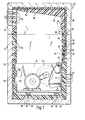
- FIG. 1 shows a device housing, generally designated 10, with a lower housing part 12 and an upper housing part 14.
- a device 16 is arranged, which in the present example has a blower 18. Otherwise, the structure of the device 16 is not essential for understanding the present invention.
- the device housing 10 comprises a rigid outer shell 20 made of plastic, metal or another suitable material, which is completely lined on the inside with an insulating layer 22 made of plastic foam.
- This insulation layer 22 thus covers the entire inner contour of the outer shell 20 with all corners, depressions, undercuts, so that no sound bridges can be formed at these points.
- An example of this is the stiffening ribs 24 formed on the outer shell 20 of the lower housing part 12. Only the projecting from the bottom of the lower housing part 12 mounting cams 26 on which the device 16 with the interposition of Schwingmetallmaschine 28 is fastened with the aid of screws 30 are only enclosed in the region of their jacket by the insulating layer 22, while the bearing surface for the Schwingmetallmaschine 28 remains uncovered.
- a mounting bracket 32 usually acts as a sound bridge, which is screwed with one leg to the device 16 and with its other leg to the outer shell 20 of the lower housing part. In order to reduce the sound transmission to a minimum here too, the mounting bracket 32 is embedded in the insulation layer 22 to such an extent that only part of the leg attached to the device 16 protrudes from the insulation layer 22.
- the insulation layer 22 In order to improve the sound-absorbing effect of the insulation layer 22, it can be provided on its inside with a profiled surface, as is shown in the area 34. It goes without saying that this profile can extend over the entire inner surface or over a desired part of the inner surface of the insulation layer 22.
- the area 34 is only intended to be an example of such a surface design.
- a rib 36 is formed on the abutting surface of the insulating layer of the lower housing part 12 facing the upper housing part 14, which rib engages in a complementary groove 38 which is formed in the corresponding abutting surface of the insulating layer 22 of the upper part 14.
- air inlet slots 40 are formed in the lower region of the lower housing part 12 and air outlet slots 42 in the upper region of the upper housing part 14.
- the sections 44 of the air inlet slots 40 running in the insulation layer 22 are cranked, i.e. designed angled in itself.
- the sound exit through the air inlet slots 40 is largely avoided.
- the air outlet slots 42, the section 46 of which extends in the insulating layer 22 are directed obliquely to the sections which extend in the outer shell 20.
- the insulation layer 22 is provided in the area of the top surface of the upper housing part 14 with an air guiding surface 48 which rises obliquely towards the air outlet slots 42.
- air guiding surfaces can be provided on the insulation layer 22 in any desired shape.
- cutouts 50 are formed in the insulating layer 22, the contours of which correspond to corresponding projections on the device 16.
- the inner layer of the insulating layer 22 can thus be completely adapted to the outer contour of the device to be accommodated.
- a layer 52 made of a specifically heavy material with material can be provided between the outer shell 20 and the insulation layer 22, as is shown on the left-hand side of FIG. 1 at the level of the device 16.
- an electrical shield in the form of a grid or perforated plate 54 can be embedded in the insulation layer 22, as is shown in the area of the upper housing part 14.
- An electrical shield in the form of a perforated plate also has a sound-absorbing function. Both the shield 54 and the heavy material layer 52 can of course extend over the entire inner circumference of the housing 10 or only over a certain part of the same. In Fig. 1 only one section was shown as an example.
- Cable management shafts can also be formed in the insulation layer 22.
- a channel-shaped profile 56 is embedded in the insulation layer 22, which is closed on its open side by the outer shell 20 and together with this forms a cable duct 58 for inserting cables 60.
- a mushroom-shaped groove 62 in cross-section or a dovetail-shaped groove 64 in cross-section is formed, into each of which a cable 65 or 66 can be pressed from the inside of the housing, which in the groove 62 or 64 is recorded.
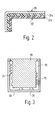
- the insulation layer 22 can also 3, the outer shell 20 is used as an outer mold, into which a correspondingly shaped inner mold 68 is inserted, whereupon the space 70 between the outer shell 20 and the inner mold 68 is foamed with an elastic plastic, which connects firmly to the outer shell 20.
- FIG. 3 shows this process schematically only for the production of the lower housing part 12.
- the sections 44 of the ventilation slots 40 are produced by shaped pieces 72 which, due to the elasticity of the plastic material, can be easily pulled out of the insulating layer after foaming.
- the objects to be embedded in the insulation layer must of course be arranged beforehand in the intermediate space 70. The techniques required for this are known per se and therefore do not need to be explained in more detail.
- Fig. 2 shows a partial section through a further embodiment of the invention, in which the insulating layer 22 is constructed from two partial layers 22a and 22b, which consist of plastic material of different densities. As a result, a larger range of sound frequencies can be effectively absorbed.
Landscapes
- Physics & Mathematics (AREA)
- General Physics & Mathematics (AREA)
- Soundproofing, Sound Blocking, And Sound Damping (AREA)
- Duct Arrangements (AREA)
- Casings For Electric Apparatus (AREA)
- Vehicle Interior And Exterior Ornaments, Soundproofing, And Insulation (AREA)
Applications Claiming Priority (2)
| Application Number | Priority Date | Filing Date | Title |
|---|---|---|---|
| DE3112591 | 1981-03-30 | ||
| DE19813112591 DE3112591C2 (de) | 1981-03-30 | 1981-03-30 | Schallisolierendes geschlossenes Gerätegehäuse |
Publications (2)
| Publication Number | Publication Date |
|---|---|
| EP0062166A2 true EP0062166A2 (fr) | 1982-10-13 |
| EP0062166A3 EP0062166A3 (fr) | 1984-02-22 |
Family
ID=6128735
Family Applications (1)
| Application Number | Title | Priority Date | Filing Date |
|---|---|---|---|
| EP82101700A Withdrawn EP0062166A3 (fr) | 1981-03-30 | 1982-03-04 | Carter d'appareil insonore et procédé pour sa fabrication |
Country Status (3)
| Country | Link |
|---|---|
| EP (1) | EP0062166A3 (fr) |
| JP (1) | JPS57169797A (fr) |
| DE (1) | DE3112591C2 (fr) |
Cited By (10)
| Publication number | Priority date | Publication date | Assignee | Title |
|---|---|---|---|---|
| EP0304398A1 (fr) * | 1987-08-21 | 1989-02-22 | Leica Aarau AG | Instrument pourvu d'une boîtier |
| WO1999022794A1 (fr) * | 1997-11-03 | 1999-05-14 | Resmed Limited | Corps de montage insonorisant, destine a un compresseur de ventilation spontanee en pression positive continue |
| US6532957B2 (en) | 1996-09-23 | 2003-03-18 | Resmed Limited | Assisted ventilation to match patient respiratory need |
| US6776155B2 (en) | 1997-05-16 | 2004-08-17 | Resmed Limited | Nasal ventilation as a treatment for stroke |
| WO2005001215A1 (fr) | 2003-06-25 | 2005-01-06 | Parker, Ronald, Brian | Dispositif d'insonorisation destine a des machines |
| US6951263B2 (en) | 2000-04-12 | 2005-10-04 | Carcoustics Tech Center Gmbh | Sound absorber, especially for motor vehicles, and a method for producing a sound absorber |
| EP1772480A1 (fr) * | 2005-10-06 | 2007-04-11 | Henkel KGaA | Amortisseur de vibrations |
| US7302950B2 (en) | 1991-12-20 | 2007-12-04 | Resmed Limited | Patient interface for respiratory apparatus |
| CN106025847A (zh) * | 2016-06-08 | 2016-10-12 | 佘峰 | 一种稳定性高的降噪电力设备防护箱 |
| DE102019117717A1 (de) * | 2019-07-01 | 2021-01-07 | Wolf Gmbh | Verkleidungsteil und Schalldämmhaube für eine Wärmepumpe |
Families Citing this family (6)
| Publication number | Priority date | Publication date | Assignee | Title |
|---|---|---|---|---|
| JP3845736B2 (ja) | 1995-09-18 | 2006-11-15 | レスメッド・リミテッド | Cpap治療又は補助された人工呼吸における圧力制御 |
| AUPO742297A0 (en) | 1997-06-18 | 1997-07-10 | Resmed Limited | An apparatus for supplying breathable gas |
| DE19839968C2 (de) * | 1998-09-02 | 2000-06-21 | Siemens Nixdorf Inf Syst | Anordnung und Verfahren zur Schalldämmung |
| DE19925661A1 (de) * | 1999-06-04 | 2000-12-07 | Volkswagen Ag | Akustische Kompaktisolation |
| DE10007419A1 (de) | 2000-02-18 | 2001-08-30 | Fujitsu Siemens Computers Gmbh | Vorrichtung zur Reduzierung des Geräuschpegels und zur Kühlung einer Komponente mit bewegten Teilen |
| DE102006058840B4 (de) * | 2006-12-13 | 2021-01-14 | Pfeiffer Vacuum Gmbh | Vakuumpumpe |
Family Cites Families (8)
| Publication number | Priority date | Publication date | Assignee | Title |
|---|---|---|---|---|
| DE1037572B (de) * | 1955-10-21 | 1958-08-28 | Licentia Gmbh | Elektrische Maschine, bei der die Blechpakete mit den sie tragenden Teilen ueber einKlebemittel vereinigt sind |
| US2989855A (en) * | 1960-03-07 | 1961-06-27 | Gen Motors Corp | Refrigerating apparatus |
| DE2045718A1 (fr) * | 1970-09-16 | 1972-03-23 | Baus H | |
| US3855028A (en) * | 1972-11-08 | 1974-12-17 | D Larson | Method of fabricating structures |
| FR2350556A1 (fr) * | 1976-05-04 | 1977-12-02 | Segic | Element prefabrique de ventilation et de climatisation |
| IT1078420B (it) * | 1977-04-20 | 1985-05-08 | Turati Giuseppe | Complesso di elementi modulari preformati,per l'insonorizzazione di apparecchiature in genere |
| DE2923077C2 (de) * | 1979-06-07 | 1987-10-22 | Klein, Schanzlin & Becker Ag, 6710 Frankenthal | Schallschutzhaube für oberflächengekühlte Elektromotoren |
| DE2930966C2 (de) * | 1979-07-31 | 1983-12-22 | Teroson Gmbh, 6900 Heidelberg | Verfahren zur Herstellung eines schalldämmenden Formteils |
-
1981
- 1981-03-30 DE DE19813112591 patent/DE3112591C2/de not_active Expired
-
1982
- 1982-03-04 EP EP82101700A patent/EP0062166A3/fr not_active Withdrawn
- 1982-03-26 JP JP57047500A patent/JPS57169797A/ja active Pending
Cited By (22)
| Publication number | Priority date | Publication date | Assignee | Title |
|---|---|---|---|---|
| EP0304398A1 (fr) * | 1987-08-21 | 1989-02-22 | Leica Aarau AG | Instrument pourvu d'une boîtier |
| US7302950B2 (en) | 1991-12-20 | 2007-12-04 | Resmed Limited | Patient interface for respiratory apparatus |
| US7931023B2 (en) | 1991-12-20 | 2011-04-26 | Resmed Limited | Patient interface assembly for CPAP respiratory apparatus |
| US8051853B2 (en) | 1996-09-23 | 2011-11-08 | Resmed Limited | Method and apparatus for providing ventilatory assistance |
| US6810876B2 (en) | 1996-09-23 | 2004-11-02 | Resmed Ltd. | Assisted ventilation to match patient respiratory need |
| US7137389B2 (en) | 1996-09-23 | 2006-11-21 | Resmed Limited | Method and apparatus for determining instantaneous inspired volume of a subject during ventilatory assistance |
| US9974911B2 (en) | 1996-09-23 | 2018-05-22 | Resmed Limited | Method and apparatus for providing ventilatory assistance |
| US8733351B2 (en) | 1996-09-23 | 2014-05-27 | Resmed Limited | Method and apparatus for providing ventilatory assistance |
| US6688307B2 (en) | 1996-09-23 | 2004-02-10 | Resmed Limited | Methods and apparatus for determining instantaneous elastic recoil and assistance pressure during ventilatory support |
| US7644713B2 (en) | 1996-09-23 | 2010-01-12 | Resmed Limited | Method and apparatus for determining instantaneous leak during ventilatory assistance |
| US6532957B2 (en) | 1996-09-23 | 2003-03-18 | Resmed Limited | Assisted ventilation to match patient respiratory need |
| US6776155B2 (en) | 1997-05-16 | 2004-08-17 | Resmed Limited | Nasal ventilation as a treatment for stroke |
| WO1999022794A1 (fr) * | 1997-11-03 | 1999-05-14 | Resmed Limited | Corps de montage insonorisant, destine a un compresseur de ventilation spontanee en pression positive continue |
| US6951263B2 (en) | 2000-04-12 | 2005-10-04 | Carcoustics Tech Center Gmbh | Sound absorber, especially for motor vehicles, and a method for producing a sound absorber |
| WO2005001215A1 (fr) | 2003-06-25 | 2005-01-06 | Parker, Ronald, Brian | Dispositif d'insonorisation destine a des machines |
| US7364221B2 (en) | 2005-10-06 | 2008-04-29 | Henkel Kommanditgesellschaft Auf Aktien | Reduction of vibration transfer |
| CN101341199B (zh) * | 2005-10-06 | 2012-03-28 | 汉高两合股份公司 | 减小振动传递 |
| WO2007039308A1 (fr) * | 2005-10-06 | 2007-04-12 | Henkel Kgaa | Reduction du transfert de vibrations |
| EP1772480A1 (fr) * | 2005-10-06 | 2007-04-11 | Henkel KGaA | Amortisseur de vibrations |
| CN106025847A (zh) * | 2016-06-08 | 2016-10-12 | 佘峰 | 一种稳定性高的降噪电力设备防护箱 |
| CN106025847B (zh) * | 2016-06-08 | 2017-12-22 | 江苏盐阜电站阀门辅机制造有限公司 | 一种稳定性高的降噪电力设备防护箱 |
| DE102019117717A1 (de) * | 2019-07-01 | 2021-01-07 | Wolf Gmbh | Verkleidungsteil und Schalldämmhaube für eine Wärmepumpe |
Also Published As
| Publication number | Publication date |
|---|---|
| EP0062166A3 (fr) | 1984-02-22 |
| DE3112591A1 (de) | 1982-10-14 |
| JPS57169797A (en) | 1982-10-19 |
| DE3112591C2 (de) | 1983-12-29 |
Similar Documents
| Publication | Publication Date | Title |
|---|---|---|
| EP0062166A2 (fr) | Carter d'appareil insonore et procédé pour sa fabrication | |
| DE1680066B2 (de) | Schiebedachkonstruktion für Kraftfahrzeuge | |
| DE2902831A1 (de) | Schall- und waermeisolationswand | |
| DE60210220T2 (de) | Doppelwandige Dämpfungsstruktur | |
| CH672932A5 (en) | Noise-attenuating wall section - contains insulating layers of different densities, with first layer held clear of front wall by distance piece | |
| DE3441769A1 (de) | Lueftungsvorrichtung fuer raeume | |
| EP0947638B1 (fr) | Panneau d'isolation pour façades extérieures de maisons | |
| DE2943953C2 (de) | Webschaftstab | |
| DE2853774C2 (de) | Verbundplatte | |
| DE102005035703B3 (de) | Abdichtanordnung | |
| EP0940518A1 (fr) | Elément de revêtment pou murs de batiments | |
| EP1233137A2 (fr) | Dispositif d'étanchéité pour le bord inférieur d'une porte sans seuil | |
| DE69810866T2 (de) | Zubehör für elektrischen Verkabelungsrohrleiter | |
| DE102015114379A1 (de) | Verfahren zum Herstellen eines Formteils zur Schalldämmung einer Einbauvorrichtung | |
| DE19959123B4 (de) | Schall- und/oder wärmedämmende Matte | |
| EP0835979B1 (fr) | Volet roulant et son cache intérieure | |
| DE3530431C2 (fr) | ||
| DE202005012384U1 (de) | Rollladenvorrichtung mit einer Revisionsöffnung, insbesondere für die Holzständerbauweise der Fertighausindustrie | |
| EP0670450B1 (fr) | Collier de fixation | |
| EP0149053A2 (fr) | Dispositif d'aération pour locaux | |
| DE3248077A1 (de) | Verbundprofil fuer fenster und/oder tueren | |
| DE20319931U1 (de) | Verbundprofil mit thermischer Trennung und fixiertem Schalelement | |
| EP1300527A2 (fr) | Dispositif de fixation de rails de listeaux, notament de rails de listeaux en forme de plinthes | |
| DE3240474A1 (de) | Brandschutzeinrichtung fuer eine gekapselte kabeldurchfuehrung durch gebaeudewaende, decken und dergleichen | |
| DE102017202547A1 (de) | Dachsystem für ein Kraftfahrzeug |
Legal Events
| Date | Code | Title | Description |
|---|---|---|---|
| PUAI | Public reference made under article 153(3) epc to a published international application that has entered the european phase |
Free format text: ORIGINAL CODE: 0009012 |
|
| AK | Designated contracting states |
Designated state(s): AT BE CH DE FR GB IT LI NL SE |
|
| PUAL | Search report despatched |
Free format text: ORIGINAL CODE: 0009013 |
|
| RHK1 | Main classification (correction) |
Ipc: G10K 11/16 |
|
| AK | Designated contracting states |
Designated state(s): AT BE CH DE FR GB IT LI NL SE |
|
| STAA | Information on the status of an ep patent application or granted ep patent |
Free format text: STATUS: THE APPLICATION IS DEEMED TO BE WITHDRAWN |
|
| 18D | Application deemed to be withdrawn |
Effective date: 19841023 |
|
| RIN1 | Information on inventor provided before grant (corrected) |
Inventor name: SCHMEYKAL, RUDOLF Inventor name: DOEINGHAUS, HERMANN |