EP0062196A2 - Gegossene Rekuperator-Röhre - Google Patents
Gegossene Rekuperator-Röhre Download PDFInfo
- Publication number
- EP0062196A2 EP0062196A2 EP82102252A EP82102252A EP0062196A2 EP 0062196 A2 EP0062196 A2 EP 0062196A2 EP 82102252 A EP82102252 A EP 82102252A EP 82102252 A EP82102252 A EP 82102252A EP 0062196 A2 EP0062196 A2 EP 0062196A2
- Authority
- EP
- European Patent Office
- Prior art keywords
- casting
- envelope
- mold
- core
- heat exchanger
- Prior art date
- Legal status (The legal status is an assumption and is not a legal conclusion. Google has not performed a legal analysis and makes no representation as to the accuracy of the status listed.)
- Withdrawn
Links
- 238000005266 casting Methods 0.000 claims abstract description 44
- 239000004576 sand Substances 0.000 claims abstract description 30
- 239000002184 metal Substances 0.000 claims abstract description 24
- 229910052751 metal Inorganic materials 0.000 claims abstract description 24
- 238000000034 method Methods 0.000 claims abstract description 19
- 239000011230 binding agent Substances 0.000 claims abstract description 10
- 239000007789 gas Substances 0.000 claims abstract description 8
- 238000001816 cooling Methods 0.000 claims description 5
- 208000015943 Coeliac disease Diseases 0.000 claims description 4
- 230000003628 erosive effect Effects 0.000 claims description 4
- 230000007797 corrosion Effects 0.000 claims description 3
- 238000005260 corrosion Methods 0.000 claims description 3
- 239000012080 ambient air Substances 0.000 claims description 2
- 239000000919 ceramic Substances 0.000 claims description 2
- 239000002320 enamel (paints) Substances 0.000 claims description 2
- 238000010438 heat treatment Methods 0.000 claims 2
- 238000010079 rubber tapping Methods 0.000 claims 1
- 239000012530 fluid Substances 0.000 abstract description 6
- 239000011796 hollow space material Substances 0.000 abstract 2
- 238000013022 venting Methods 0.000 abstract 1
- 229910001018 Cast iron Inorganic materials 0.000 description 4
- 238000004519 manufacturing process Methods 0.000 description 3
- 238000007711 solidification Methods 0.000 description 2
- 230000008023 solidification Effects 0.000 description 2
- 239000010425 asbestos Substances 0.000 description 1
- 230000015572 biosynthetic process Effects 0.000 description 1
- 239000000470 constituent Substances 0.000 description 1
- 230000003247 decreasing effect Effects 0.000 description 1
- 230000000694 effects Effects 0.000 description 1
- 238000004534 enameling Methods 0.000 description 1
- 239000012535 impurity Substances 0.000 description 1
- 239000000463 material Substances 0.000 description 1
- 230000002093 peripheral effect Effects 0.000 description 1
- 230000002787 reinforcement Effects 0.000 description 1
- 229910052895 riebeckite Inorganic materials 0.000 description 1
- 239000007787 solid Substances 0.000 description 1
- 239000011800 void material Substances 0.000 description 1
- 239000002023 wood Substances 0.000 description 1
Images
Classifications
-
- F—MECHANICAL ENGINEERING; LIGHTING; HEATING; WEAPONS; BLASTING
- F28—HEAT EXCHANGE IN GENERAL
- F28F—DETAILS OF HEAT-EXCHANGE AND HEAT-TRANSFER APPARATUS, OF GENERAL APPLICATION
- F28F3/00—Plate-like or laminated elements; Assemblies of plate-like or laminated elements
- F28F3/02—Elements or assemblies thereof with means for increasing heat-transfer area, e.g. with fins, with recesses, with corrugations
- F28F3/04—Elements or assemblies thereof with means for increasing heat-transfer area, e.g. with fins, with recesses, with corrugations the means being integral with the element
- F28F3/042—Elements or assemblies thereof with means for increasing heat-transfer area, e.g. with fins, with recesses, with corrugations the means being integral with the element in the form of local deformations of the element
-
- B—PERFORMING OPERATIONS; TRANSPORTING
- B22—CASTING; POWDER METALLURGY
- B22D—CASTING OF METALS; CASTING OF OTHER SUBSTANCES BY THE SAME PROCESSES OR DEVICES
- B22D25/00—Special casting characterised by the nature of the product
- B22D25/02—Special casting characterised by the nature of the product by its peculiarity of shape; of works of art
-
- B—PERFORMING OPERATIONS; TRANSPORTING
- B22—CASTING; POWDER METALLURGY
- B22C—FOUNDRY MOULDING
- B22C9/00—Moulds or cores; Moulding processes
- B22C9/22—Moulds for peculiarly-shaped castings
- B22C9/24—Moulds for peculiarly-shaped castings for hollow articles
- B22C9/26—Moulds for peculiarly-shaped castings for hollow articles for ribbed tubes; for radiators
-
- F—MECHANICAL ENGINEERING; LIGHTING; HEATING; WEAPONS; BLASTING
- F28—HEAT EXCHANGE IN GENERAL
- F28F—DETAILS OF HEAT-EXCHANGE AND HEAT-TRANSFER APPARATUS, OF GENERAL APPLICATION
- F28F21/00—Constructions of heat-exchange apparatus characterised by the selection of particular materials
- F28F21/08—Constructions of heat-exchange apparatus characterised by the selection of particular materials of metal
-
- Y—GENERAL TAGGING OF NEW TECHNOLOGICAL DEVELOPMENTS; GENERAL TAGGING OF CROSS-SECTIONAL TECHNOLOGIES SPANNING OVER SEVERAL SECTIONS OF THE IPC; TECHNICAL SUBJECTS COVERED BY FORMER USPC CROSS-REFERENCE ART COLLECTIONS [XRACs] AND DIGESTS
- Y10—TECHNICAL SUBJECTS COVERED BY FORMER USPC
- Y10T—TECHNICAL SUBJECTS COVERED BY FORMER US CLASSIFICATION
- Y10T29/00—Metal working
- Y10T29/49—Method of mechanical manufacture
- Y10T29/4935—Heat exchanger or boiler making
- Y10T29/49357—Regenerator or recuperator making
Definitions
- This invention relates generally to the method of casting a metallic plate type heat exchanger as is used for the transfer of heat from one gaseous fluid to another.
- cast iron is considered a preferred constituent inasmuch as cast iron has unique properties that effect resistance to corrosion and erosion from the gases.
- U.S. Patents 1,992,097, 2,537,276 and U.K. Patent 1,197,409 are directed to various arrangements that utilize cast iron plates held in a spaced relation by a multiplicity of longitudinal bolts.
- the individual plates of the heat exchanger are first assembled by hand, bolts are inserted through holes in flanges at the sides of the plates, and fastening means such as nuts are then individually placed thereon and secured to provide a completely assembled envelope unit.
- Gasket material such as pliable asbestos rope must be placed between envelope plates before they are bolted together to provide a satisfactory seal that precludes leakage of fluid between envelope plates.
- This invention is therefore directed to an improved method of casting a hollow envelope body for a recuperative heat exchanger.
- the entire envelope is cast as an integral unit in a single casting operation that eliminates excessive casting time and assembly.
- a heretofore necessary flange for connecting opposite sides of the envelope unit is eliminated, thus decreasing the amount of molten metal required and the final weight of a completed envelope.
- the envelope is cast integrally, there is no inherent leakage, so the cost of operation is significantly reduced while the active life expectancy and effectiveness are conversely greatly enhanced.
- a monolithic block of packed sand having a suitable binder therein is formed in a core box to have the outer configuration of the hollow internal space enclosed within a heat exchange envelope.
- This is standard practice as outlined in my previous application S.N. 218,892 filed on December 22, 1980.
- the sand that comprises the sand core is mixed with a commercial grade binder that has a controlled rate of disintegration at high casting temperatures whereby said core will partially disintegrate to permit removal thereof after the casting has cooled.
- the core is formed as a packed sand body that includes similar end segments with one or more identical but separate center segments therebetween. Protuberances that extend laterally from the sides of each segment of the core are held in depressions formed in the sides of a sand mold having the predetermined outlines of the envelope. When the core is - suspended within the mold there is formed a cavity therebetween which is then filled with molten casting metal. Upon cooling, the molten metal solidifies to form an integral heat exchange envelope having continuous end and center sections. Inasmuch as the protuberances extending from the core to the mold produce a void in the finished casting, these opendings are accordingly tapped and fitting with a tightly fitting plug that precludes fluid leakage therethrough.
- the sand mold is formed in end and center segments having a predetermined capacity much like the formation of the sand core.
- abutting mold segments are contained in a strongback or flask designed to have a strength sufficient to withstand the pressure caused by the molten metal.
- the size and capacity of an envelope unit may be readily made to have a predetermined capacity designed to fulfill. a particular function.
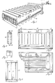
- a conventional pattern of wood or meta.1 having an outer configuration corresponding to the outer configuration of the envelope shown in Figure 1 is first made in accordance with accepted procedures.
- the pattern for each envelope is made in modular form to include end and center sections whereby an envelope having a predetermined length, surface area and heat exchange capacity may be constructed by adding to or deleting from the number of center sections between similar ends of the heat exchanger.
- the dividing line between end and center sections is represented by the dotted line that extends through plug 34.
- a sand mold 10 is formed.
- the sand that is used to form the mold is mixed with a standard binder that is adapted to harden upon contact with the ambient air.
- the mold is formed in the conventional manner, and it includes depressions 11 along the sides thereof that are adapted to support protuberances 26 that extend Ia+erally from the sand core as shown by Figure 3.
- the sand mold includes depressions for sprues 12, gates and risers 16 as shown in Figures 2 and 3, whereby placing the two mold halves together will form a continuous passageway for the supply of molten metal into the mold.
- a sand core 18 is formed to fit loosely inside the mold to provide a clearance space therebetween that, when filled with molten casting metal, becomes the envelope.
- the sand core 18 has an outer configuration corresponding to the inverse of the inside walls of the envelope.
- the sand core is formed of end modules 8-A and center modules 8-B that fit in end-to-end abutment to lie in the cavity of the mold to form a clearance space 25 as shown in Figure 3.
- Each module of the core has protuberances 26 that extend laterally therefrom to the depressions 11 on the side of the sand mold whereby abutting modules of the sand core 18 are held firmly against shifting so they will at all times be in exact abutment thereby providing a smoothly contoured inner surface of the heat exchanger envelope.
- Irregularities formed in the end faces of abutting modules as shown in Figure 5 further preclude shifting of individual modules.
- the sand comprising the sand core 18 is mixed with a' binder that is adapted to harden at low heat (150 C to 250 C), and then break down when exposed to the high temperature of the molten casting metal after it has been poured into the clearance space between the core and the mold.
- a' binder that is adapted to harden at low heat (150 C to 250 C)
- the segments of the sand core remain monolithic sand blocks at lower temperatures, but after the binder has been heated by the high temperature of the molten metal they disintegrate adjacent the molten metal and allow the sand to return to a praticulate state.
- the particular sand of the core together with the remnants of the core are readily removed from the newly cast envelope.
- Sand core segments are preferably made up and stored whereby they may be made available for use at any given time.
- the segments of the core are formed with irregularities 20 that mate with other irregularities of an adjacent segment.
- a male irregularity at one end of a segment matches up with a female irregularity at the end of an adjacent segment to insure direct alignment of one segment with a segment adjacent thereto.
- each end segment 8-A of the sand core comprises a solid block that extends past the mold cavity and is supported in a suitable depression 33 at the end of the mold in the manner shown by Figure 3 whereby a clearance space beween the end of the core and the mold defines the open inlet and outlet ends of the envelope casting.
- the metallic envelope will have voids or openings 31 where each protuberance 26 occurs. These openings are subsequently tapped to thereby adapt them to receive a threaded plug 34 that precludes fluid flow therethrough.
- These same openings 31 are instrumental in removal of particulate sand and other core remnants from the envelope after the casting process has been completed, and during the casting process these openings form an escape route for gases produced by the action of hot molten metal upon the binder of the core. These gases may slowly vent through the interstices between grains of sand in the mold, although additional vents may be formed in the mold outward from the depressions 11 to provide a suitable path for gases from the core to escape to the atmosphere.
- a heat exchange envelope comprised of cast iron inherently has a high resistance to corrosion and erosion, an even greater resistance may be imparted thereto by bonding a ceramic enamel coating to the surface thereof. Accordingly, before the newly cast envelope is permitted to corrode it is preferably subjected to standard enameling procedures.
Landscapes
- Engineering & Computer Science (AREA)
- Mechanical Engineering (AREA)
- Physics & Mathematics (AREA)
- Thermal Sciences (AREA)
- General Engineering & Computer Science (AREA)
- Molds, Cores, And Manufacturing Methods Thereof (AREA)
- Heat-Exchange Devices With Radiators And Conduit Assemblies (AREA)
Applications Claiming Priority (2)
| Application Number | Priority Date | Filing Date | Title |
|---|---|---|---|
| US246214 | 1981-04-02 | ||
| US06/246,214 US4416044A (en) | 1981-04-02 | 1981-04-02 | Cast recuperator tube |
Publications (2)
| Publication Number | Publication Date |
|---|---|
| EP0062196A2 true EP0062196A2 (de) | 1982-10-13 |
| EP0062196A3 EP0062196A3 (de) | 1983-06-29 |
Family
ID=22929756
Family Applications (1)
| Application Number | Title | Priority Date | Filing Date |
|---|---|---|---|
| EP82102252A Withdrawn EP0062196A3 (de) | 1981-04-02 | 1982-03-19 | Gegossene Rekuperator-Röhre |
Country Status (9)
| Country | Link |
|---|---|
| US (1) | US4416044A (de) |
| EP (1) | EP0062196A3 (de) |
| JP (1) | JPS57175054A (de) |
| KR (1) | KR870000974B1 (de) |
| AU (1) | AU8217782A (de) |
| BR (1) | BR8201872A (de) |
| CA (1) | CA1185067A (de) |
| ES (1) | ES8303151A1 (de) |
| IN (1) | IN155795B (de) |
Cited By (4)
| Publication number | Priority date | Publication date | Assignee | Title |
|---|---|---|---|---|
| WO1986002863A1 (en) * | 1984-11-05 | 1986-05-22 | The Air Preheater Company, Inc. | Method of making a finned cast recuperator tube |
| WO1993025332A1 (en) * | 1992-06-15 | 1993-12-23 | Rank Brimar Limited | Multipin structures |
| CN106077484A (zh) * | 2016-08-16 | 2016-11-09 | 黄小虎 | 一种多用途整体调温板及其制作方法 |
| CN106271487A (zh) * | 2016-08-16 | 2017-01-04 | 安徽天祥空调科技有限公司 | 一种空调散热管的生产工艺 |
Families Citing this family (4)
| Publication number | Priority date | Publication date | Assignee | Title |
|---|---|---|---|---|
| KR101017255B1 (ko) * | 2010-10-05 | 2011-02-28 | 정희철 | 열교환기용 핀 블록유닛 성형을 위한 주조금형 |
| JP2012131331A (ja) * | 2010-12-21 | 2012-07-12 | Sanden Corp | 車両用加熱装置 |
| JP5867235B2 (ja) | 2011-05-16 | 2016-02-24 | 三菱電機株式会社 | 磁気センサ装置 |
| CN108145833B (zh) * | 2018-01-08 | 2023-07-21 | 郑州远东耐火材料有限公司 | 锆刚玉电熔砖普通浇铸冒口圈模具及冒口圈生产方法 |
Family Cites Families (8)
| Publication number | Priority date | Publication date | Assignee | Title |
|---|---|---|---|---|
| US1286375A (en) * | 1916-07-31 | 1918-12-03 | John C Mclachlan | Method of producing cast shell-projectiles. |
| US1657444A (en) * | 1926-10-06 | 1928-01-24 | Robert K Prince | Process of and means for preparing molds |
| US1804400A (en) * | 1927-08-19 | 1931-05-12 | Vernon J Davis | Method of molding |
| FR647780A (fr) * | 1928-01-23 | 1928-11-30 | H B Smith Company | Procédé et moyen pour préparer des moules |
| GB404763A (en) * | 1932-09-19 | 1934-01-25 | Gurney Foundry Company Ltd | Improvements in or relating to moulds for casting |
| US3554271A (en) * | 1968-03-18 | 1971-01-12 | Acme Cleveland Corp | Molding assembly method |
| FR1598236A (de) * | 1968-11-29 | 1970-07-06 | ||
| DE2620515C3 (de) * | 1975-05-16 | 1982-12-16 | Remeha Fabrieken B.V., Apeldoorn | Gußmetallener Wärmetauscher, insbesondere Zentralheizkessel |
-
1981
- 1981-04-02 US US06/246,214 patent/US4416044A/en not_active Expired - Fee Related
-
1982
- 1982-02-02 IN IN128/CAL/82A patent/IN155795B/en unknown
- 1982-02-12 CA CA000396218A patent/CA1185067A/en not_active Expired
- 1982-03-19 EP EP82102252A patent/EP0062196A3/de not_active Withdrawn
- 1982-03-25 ES ES510807A patent/ES8303151A1/es not_active Expired
- 1982-03-30 JP JP57050289A patent/JPS57175054A/ja active Pending
- 1982-03-30 AU AU82177/82A patent/AU8217782A/en not_active Abandoned
- 1982-04-01 BR BR8201872A patent/BR8201872A/pt unknown
- 1982-04-02 KR KR8201465A patent/KR870000974B1/ko not_active Expired
Cited By (4)
| Publication number | Priority date | Publication date | Assignee | Title |
|---|---|---|---|---|
| WO1986002863A1 (en) * | 1984-11-05 | 1986-05-22 | The Air Preheater Company, Inc. | Method of making a finned cast recuperator tube |
| WO1993025332A1 (en) * | 1992-06-15 | 1993-12-23 | Rank Brimar Limited | Multipin structures |
| CN106077484A (zh) * | 2016-08-16 | 2016-11-09 | 黄小虎 | 一种多用途整体调温板及其制作方法 |
| CN106271487A (zh) * | 2016-08-16 | 2017-01-04 | 安徽天祥空调科技有限公司 | 一种空调散热管的生产工艺 |
Also Published As
| Publication number | Publication date |
|---|---|
| US4416044A (en) | 1983-11-22 |
| JPS57175054A (en) | 1982-10-27 |
| KR870000974B1 (ko) | 1987-05-16 |
| BR8201872A (pt) | 1983-03-08 |
| AU8217782A (en) | 1982-10-07 |
| EP0062196A3 (de) | 1983-06-29 |
| ES510807A0 (es) | 1983-02-01 |
| CA1185067A (en) | 1985-04-09 |
| ES8303151A1 (es) | 1983-02-01 |
| KR830009826A (ko) | 1983-12-23 |
| IN155795B (de) | 1985-03-09 |
Similar Documents
| Publication | Publication Date | Title |
|---|---|---|
| US6626230B1 (en) | Multi-wall core and process | |
| US4617977A (en) | Ceramic casting mould and a method for its manufacture | |
| US4416044A (en) | Cast recuperator tube | |
| JP2001514374A5 (de) | ||
| CN113070453B (zh) | 齿轮箱铸件的铸造方法 | |
| US3364951A (en) | Heat exchanger | |
| US2688780A (en) | Machine and process for forming hollow sand-resin cores | |
| US4417615A (en) | Cast iron recuperator | |
| JPH0635047B2 (ja) | 中子の除去方法 | |
| US4089302A (en) | Cast metal heat exchanger, as well as mould therefor | |
| US4572269A (en) | Method of manufacturing cooling plates for use in metallurgical furnaces and a cooling plate | |
| FI66551B (fi) | Foerfarande foer gjutning av metall i gasgenomslaeppliga formar | |
| US4574865A (en) | Method of making a finned cast recuperator tube | |
| JPS63101066A (ja) | 鋳鉄金型の冷却孔の鋳造方法 | |
| CN116422835A (zh) | 用于船用柴油机飞轮的无冒口铸造方法 | |
| JP3545538B2 (ja) | 鋳抜き穴形成用中子ピースの製造方法 | |
| JPS603960A (ja) | 冷却水路を内蔵した鋳物の製造法 | |
| RU2146183C1 (ru) | Отливка блока цилиндров двигателя внутреннего сгорания и способ ее получения | |
| DE102005030814B4 (de) | Gussform für den Metallguss | |
| SU799900A1 (ru) | Литейна керамическа форма поВыплАВл ЕМыМ МОдЕл М | |
| JPH0234248A (ja) | 鋳造金型に冷却水路管を形成させる方法 | |
| CN121732763A (zh) | 一种基于3d打印砂型的低压铸造升液装置 | |
| JPH02200372A (ja) | 鋳造法 | |
| JPH03248742A (ja) | ロストワックス鋳造用アタッチメント | |
| JPS6021021B2 (ja) | 熱交換器の製造方法 |
Legal Events
| Date | Code | Title | Description |
|---|---|---|---|
| PUAI | Public reference made under article 153(3) epc to a published international application that has entered the european phase |
Free format text: ORIGINAL CODE: 0009012 |
|
| AK | Designated contracting states |
Designated state(s): BE DE FR |
|
| PUAL | Search report despatched |
Free format text: ORIGINAL CODE: 0009013 |
|
| AK | Designated contracting states |
Designated state(s): BE DE FR |
|
| STAA | Information on the status of an ep patent application or granted ep patent |
Free format text: STATUS: THE APPLICATION IS DEEMED TO BE WITHDRAWN |
|
| 18D | Application deemed to be withdrawn |
Effective date: 19840610 |
|
| RIN1 | Information on inventor provided before grant (corrected) |
Inventor name: MACLER, PAUL LEROY Inventor name: STOCKMAN, RICHARD FRANKLIN |