EP0062260B2 - Saw buckle with gang saw blade - Google Patents
Saw buckle with gang saw blade Download PDFInfo
- Publication number
- EP0062260B2 EP0062260B2 EP82102562A EP82102562A EP0062260B2 EP 0062260 B2 EP0062260 B2 EP 0062260B2 EP 82102562 A EP82102562 A EP 82102562A EP 82102562 A EP82102562 A EP 82102562A EP 0062260 B2 EP0062260 B2 EP 0062260B2
- Authority
- EP
- European Patent Office
- Prior art keywords
- saw blade
- fillets
- mill
- holder
- width
- Prior art date
- Legal status (The legal status is an assumption and is not a legal conclusion. Google has not performed a legal analysis and makes no representation as to the accuracy of the status listed.)
- Expired - Lifetime
Links
- 238000003780 insertion Methods 0.000 claims abstract description 11
- 230000037431 insertion Effects 0.000 claims abstract description 9
- 230000000149 penetrating effect Effects 0.000 description 2
- 238000004519 manufacturing process Methods 0.000 description 1
- 230000000284 resting effect Effects 0.000 description 1
- IHQKEDIOMGYHEB-UHFFFAOYSA-M sodium dimethylarsinate Chemical class [Na+].C[As](C)([O-])=O IHQKEDIOMGYHEB-UHFFFAOYSA-M 0.000 description 1
Images

Classifications
-
- B—PERFORMING OPERATIONS; TRANSPORTING
- B27—WORKING OR PRESERVING WOOD OR SIMILAR MATERIAL; NAILING OR STAPLING MACHINES IN GENERAL
- B27B—SAWS FOR WOOD OR SIMILAR MATERIAL; COMPONENTS OR ACCESSORIES THEREFOR
- B27B3/00—Gang saw mills; Other sawing machines with reciprocating saw blades, specially designed for length sawing of trunks
- B27B3/28—Components
- B27B3/30—Blade attachments, e.g. saw buckles; Stretching devices
Definitions
- the invention relates to a frame saw tang with frame saw blade which can be inserted into the frame saw tang by an insertion-insertion movement and carries strips fastened on both sides at the end edges, which extend from the toothed saw blade edge in the width direction of the saw blade over a partial width thereof and have supporting surfaces which extend support on counter surfaces of a frame saw fishing box, the strips being received inside the fishing box and the strips being able to be implemented in a row of holes extending across the entire width of the saw blade in the transverse direction to the rear edge of the saw blade.
- a frame saw tang with frame saw blade of the type mentioned is known from AT-A-279 138. Rectangular strips are provided, which can be implemented by means of a row of holes extending across the entire width of the saw blade in the transverse direction to the rear edge of the saw blade. For this purpose, the strips have a smaller dimension than the width of the saw blade.
- the known device is disadvantageous in terms of handling, since due to the relatively long strips to the width of the saw blade, the push-in movement into the fishing box is difficult, a tedious alignment with regard to the insertion depth has to be carried out and because such saw blades with strips that are shortened compared to the saw blade width are very difficult strongly tend to vibrate. Such vibrations then require a very careful one Handling of the entire gate, in particular the cutting performance must be reduced. The operator can only continue working with sensitive handling.
- a gang saw blade is known from AT-A-297 304, the strips of which are shorter than the saw blade width have an area which extends beyond the fishing pocket.
- the fishing bag is designed to engage a slider rod.
- a slider rod of this type cannot exert lateral clamping pressure on the load.
- the strips on both sides of the saw blade are screwed outside the area beyond the fishing pocket.
- the object of the invention is to provide a generic frame saw tang with frame saw blade which is more advantageous in use.
- the strips have a length approximately corresponding to the remaining width of a maximally sharpened saw blade and one of the strips with its end face facing the saw blade rear edge can be brought into contact with a stop provided in the fishing box, the distance from the front edge of the fishing box corresponds approximately to the length of a bar and that the area of the fishing box facing the center of the saw blade is widened beyond the stop in the direction of the rear edge of the saw blade.
- a generic frame saw tang with frame saw blade of particularly increased utility value is created: the desired short insertion path is achieved by means of only short rails, which practically have the width of the fishing box. These strips, which in their length essentially correspond to the remaining width of a maximally sharpened frame saw blade, require only one for the insertion-insertion movement very little free space. The strip-equipped saw blade can therefore be handled very well. The strips can be adjusted in the row of holes provided over the entire width of the frame saw blade in the direction of the back edge of the saw blade.
- the exact insertion limit at both ends of the saw results from the fact that one of the strips, with its end face facing the saw blade rear edge, comes up against a stop of the frame saw fishing box, the distance from the front edge of the frame saw fishing box approximately corresponding to the length of the strips. Basically, a very large frame saw blade width can be assumed, which significantly increases the usage times. The short strip length has an economic impact on production.
- the further structure is selected such that the gang saw fishing box has a greater width in its area facing the center of the saw blade than in its area facing the shaft. The corresponding widening level coincides with the height of the counter surfaces of the frame saw fishing box.
- an advantageous embodiment of the frame saw fishing box is made such that the support surfaces of the strips are stepped in such a way that a wing-like projecting strip section protrudes into the saw passage gap of the frame saw fishing box. Taking into account the undercut of the support surface both on the bar and on the counter surfaces of the frame saw fishing box, a pressure component results with respect to the bars. This makes it practically possible to get by with a single screw pin, to which only one or two dowel-like centering pins entering the row of holes have to be assigned.
- the gang saw blade has a row of holes running parallel to these in the region of the end edges and consisting of holes 5 which are at the same, narrow distance from one another.
- the strips 4 start from the toothed edge 1 ′′′ of the saw blade.
- the length ratio of bar to frame saw blade width is approximately 1: 2.
- each gang saw fishing box 2 has a stop 7 at the end of the saw passage gap 6 thereof.
- the end face 8 of one of the strips 4 arranged in pairs occurs in the insertion direction ⁇ ligating.
- the distance of the stop 7 from the front edge 9 of the frame saw fishing box 2 corresponds approximately to the length of the strips 4.
- the gang saw fishing box 2 has a greater width in its lower region facing the center of the saw blade (upper end of the saw blade 1 ') than in its region facing the shaft 3.
- the widening zone extends in the direction of the saw blade rear edge 1 ⁇ and is designated by 10. The latter forms wing-like projections.
- the widening level St coincides with the height of the counter surface 2 '.
- the support surfaces 4 'of the strips 4 and the counter surfaces 2' of the fishing box 2 are undercut in opposite directions, so that a spreading tendency of the pocket walls forming the fishing box is effectively prevented. Rather, a Kratt component that contracts the pocket walls under load occurs.
- This is also used in the sense of supporting the attachment of the strips 4, for which the strips 4 are stepped in such a way that a wing-like protruding strip section 11 resting on the broad sides of the saw blade remains, which protrudes into a corresponding recess 12 in the saw passage gap 6.
- the strip section 11 is subjected to pressure in the direction of the saw blade broad surface and is thus clamped.
- the screw pin 13 is further flanked by two centering pins 16, which, also penetrating the holes 5 of the row of holes, also define the strips 4.
- the fishing box itself secures the axial position of the centering pin 16 with its pocket inner walls, which can also have edge notches.
Landscapes
- Life Sciences & Earth Sciences (AREA)
- Engineering & Computer Science (AREA)
- Mechanical Engineering (AREA)
- Wood Science & Technology (AREA)
- Forests & Forestry (AREA)
- Knives (AREA)
- Fishing Rods (AREA)
- Nonmetal Cutting Devices (AREA)
- Sawing (AREA)
Abstract
Description
Die Erfindung betrifft eine Gattersägenangel mit Gattersägenblatt, das durch eine Einsteck-Einschubbewegung in die Gattersägenangel einbringbar ist und an den Endkanten beidseitig befestigte Leisten trägt, die von der gezahnten Sägeblattkante ausgehend sich in Breitenrichtung des Sägeblattes über eine Teilbreite desselben erstrecken und Stützflächen haben, die sich auf Gegenflächen eines Gattersägen-Angelkastens abstützen, wobei die Leisten im Inneren des Angelkastens aufgenommen sind und die Leisten in einer sich über die gesamte Sägeblattbreite erstreckenden Reihe von Löchern in Querrichtung zur Sägeblatt-Rückkante umsetzbar sind.The invention relates to a frame saw tang with frame saw blade which can be inserted into the frame saw tang by an insertion-insertion movement and carries strips fastened on both sides at the end edges, which extend from the toothed saw blade edge in the width direction of the saw blade over a partial width thereof and have supporting surfaces which extend support on counter surfaces of a frame saw fishing box, the strips being received inside the fishing box and the strips being able to be implemented in a row of holes extending across the entire width of the saw blade in the transverse direction to the rear edge of the saw blade.
Eine Gattersägenangel mit Gattersägenblatt der eingangs genannten Art ist aus der AT-A-279 138 bekannt. Dabei sind rechteckförmige Leisten vorgesehen, welche mittels einer sich über die gesamte Sägeblattbreite erstreckenden Reihe von Löchern in Querrichtung zur Sägeblatt-Rückkante umsetzbar sind. Hierzu weisen die Leisten ein geringeres Maß als die Breite des Sägeblattes auf. Die bekannte Vorrichtung ist handhabungstechnisch von Nachteil, da aufgrund der zur Breite des Sägeblattes relativ langen Leisten die Einsteck-Einschubbewegung in den Angelkasten erschwert ist, ein mühsames Ausrichten im Hinblick auf die Einstecktiefe zu erfolgen hat und weil derartige Sägeblätter mit gegenüber der Sägeblattbreite verkürzten Leisten sehr stark zum Vibrieren neigen. Derartige Vibrationen verlangen dann eine ganz vorsichtige Handhabung des gesamten Gatters, insbesondere muß die Schnittleistung reduziert werden. Der Betreiber kann nur noch unter feinfühligster Handhabung weiterarbeiten.A frame saw tang with frame saw blade of the type mentioned is known from AT-A-279 138. Rectangular strips are provided, which can be implemented by means of a row of holes extending across the entire width of the saw blade in the transverse direction to the rear edge of the saw blade. For this purpose, the strips have a smaller dimension than the width of the saw blade. The known device is disadvantageous in terms of handling, since due to the relatively long strips to the width of the saw blade, the push-in movement into the fishing box is difficult, a tedious alignment with regard to the insertion depth has to be carried out and because such saw blades with strips that are shortened compared to the saw blade width are very difficult strongly tend to vibrate. Such vibrations then require a very careful one Handling of the entire gate, in particular the cutting performance must be reduced. The operator can only continue working with sensitive handling.
Aus der AT-A-297 304 ist ein Gattersägenblatt bekannt, dessen kürzer als die Sägeblattbreite ausgebildete Leisten einen über die Angeltasche hinausgehenden Bereich aufweisen. Die Angeltasche ist zum Eingriff einer Gleitstückangel ausgebildet. Eine derartige Gleitstückangel kann keinen seitlichen Einspanndruck auf die Beleistung ausüben. Eine Verschraubung der beidseitig des Sägeblattes gelegenen Leisten erfolgt außerhalb des über die Angeltasche hinausgehenden Bereiches.A gang saw blade is known from AT-A-297 304, the strips of which are shorter than the saw blade width have an area which extends beyond the fishing pocket. The fishing bag is designed to engage a slider rod. A slider rod of this type cannot exert lateral clamping pressure on the load. The strips on both sides of the saw blade are screwed outside the area beyond the fishing pocket.
Aufgabe der Erfindung ist es, eine gattungsgemäße Gattersägenangel mit Gattersägenblatt gebrauchsvorteilhafter auszubilden.The object of the invention is to provide a generic frame saw tang with frame saw blade which is more advantageous in use.
Diese Aufgabe wird erfindungsgemäß dadurch gelöst, daß die Leisten eine etwa der Restbreite eines maximal heruntergeschärf ten Sägeblattes entsprechende Länge aufweisen und eine der Leisten mit ihrer der Sägeblatt-Rückkante zugekehrten Stirnfläche in Anlage mit einem im Angelkasten vorgesehenen Anschlag bringbar ist, dessen Abstand von der Vorderkante des Angelkastens etwa der Länge einer Leiste entspricht und daß der Angelkasten an seinem der Sägeblattmitte zugekehrten Bereich über den Anschlag hinaus in Richtung der SägeblattRückkante verbreitert ist.This object is achieved in that the strips have a length approximately corresponding to the remaining width of a maximally sharpened saw blade and one of the strips with its end face facing the saw blade rear edge can be brought into contact with a stop provided in the fishing box, the distance from the front edge of the fishing box corresponds approximately to the length of a bar and that the area of the fishing box facing the center of the saw blade is widened beyond the stop in the direction of the rear edge of the saw blade.
Zufolge solcher Ausgestaltung ist eine gattungsgemäße Gattersägenangel mit Gattersägenblatt von insbesondere erhöhtem Gebrauchswert geschaffen: Der angestrebte kurze Einschubweg wird über nur kurz ausgebildete, etwa praktisch die Breite des Angelkastens aufweisende Leisten erreicht. Diese in ihrer Länge im wesentlichen der Restbreite eines maximal heruntergeschärften Gattersägenblattes entsprechenden Leisten benötigen für die Einsteck-Einschubbewegung nur einen sehr kleinen Freiraum. Das leistenbestückte Sägeblatt läßt sich daher ausgezeichnet handhaben. Die Leisten lassen sich in der auf ganzer Breite des Gattersägenblattes vorgesehenen Lochreihe in Richtung der Sägeblattrückenkante verstellen. Die exakte jeweilige Einschubbegrenzung an beiden Sägeenden ergibt sich dadurch, daß eine der Leisten mit ihrer der Sägeblatt-Rückkante zugekehrten Stirnfläche gegen einen Anschlag des Gattersägen-Angelkastens tritt, dessen Abstand von der Vorderkante des Gattersägen-Angelkastens etwa der Länge der Leisten entspricht. Grundsätzlich kann von einer ganz erheblichen Gattersägenblatt-Breite ausgegangen werden, was die Nutzungszeiten erheblich heraufsetzt. Die geringe Leistenlänge wirkt sich bei der Fertigung wirtschaftlich aus. Um den Reserveüberstand trotz schmaler bzw. normaler Angelkastenbreite vibrationsfrei zu halten, ist der weitere Aufbau dahingehend gewählt, daß der Gattersägen-Angelkasten in seinem der Sägeblattmitte zugekehrten Bereich eine größere Breite besitzt als in seinem dem Schaft zugekehrten Bereich. Die entsprechende Verbreiterungsstufe fällt mit der Höhe der Gegenflächen des Gattersägen-Angelkastens zusammen. Der entsprechende Überstand trägt den die Einschubtiefe begrenzenden Anschlag. Weiterhin ist eine vorteilhafte Ausgestaltung des Gattersägen-Angelkastens dahingehend vorgenommen, daß die Stützflächen der Leisten stufenförmig abgesetzt sind derart, daß ein flügelartig vorstehender Leistenabschnitt in den Sägendurchtrittsspalt des Gattersägen-Angelkastens ragt. Unter Berücksichtigung des Stützflächen-Hinterschnitts sowohl an der Leiste als auch an den Gegenflächen des Gattersägen-Angelkastens ergibt sich dabei eine Andrückkomponente bezüglich der Leisten. Dadurch kommt man praktisch mit einem einzigen Schraubzapfen aus, dem bloß noch beidseitig ein oder zwei in die Lochreihe eintretende, paßstiftartige Zentrierzapfen zugeordnet werden müssen.As a result of such an embodiment, a generic frame saw tang with frame saw blade of particularly increased utility value is created: the desired short insertion path is achieved by means of only short rails, which practically have the width of the fishing box. These strips, which in their length essentially correspond to the remaining width of a maximally sharpened frame saw blade, require only one for the insertion-insertion movement very little free space. The strip-equipped saw blade can therefore be handled very well. The strips can be adjusted in the row of holes provided over the entire width of the frame saw blade in the direction of the back edge of the saw blade. The exact insertion limit at both ends of the saw results from the fact that one of the strips, with its end face facing the saw blade rear edge, comes up against a stop of the frame saw fishing box, the distance from the front edge of the frame saw fishing box approximately corresponding to the length of the strips. Basically, a very large frame saw blade width can be assumed, which significantly increases the usage times. The short strip length has an economic impact on production. In order to keep the reserve projection free of vibrations despite the narrow or normal fishing box width, the further structure is selected such that the gang saw fishing box has a greater width in its area facing the center of the saw blade than in its area facing the shaft. The corresponding widening level coincides with the height of the counter surfaces of the frame saw fishing box. The corresponding overhang carries the stop limiting the insertion depth. Furthermore, an advantageous embodiment of the frame saw fishing box is made such that the support surfaces of the strips are stepped in such a way that a wing-like projecting strip section protrudes into the saw passage gap of the frame saw fishing box. Taking into account the undercut of the support surface both on the bar and on the counter surfaces of the frame saw fishing box, a pressure component results with respect to the bars. This makes it practically possible to get by with a single screw pin, to which only one or two dowel-like centering pins entering the row of holes have to be assigned.
Weitere Vorteile des Gegenstandes der Erfindung sind nachstehend anhand eines zeichnerisch veranschaulichten Ausführungsbeispieles näher erläutert. Es zeigt:
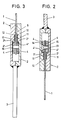
Figur 1 Gattersägenangeln und Gattersägenblatt in Seitenansicht,Figur 2 den Schnitt gemäß Linie II-II in Fig. 1 undFigur 3 den Schnitt gemäß Linie III-III in Fig. 1.
- FIG. 1 frame saw fishing and frame saw blade in side view,
- Figure 2 shows the section along line II-II in Fig. 1 and
- 3 shows the section along line III-III in FIG. 1st
Die an den Enden 1′ eines Gattersägenblattes 1 angreifenden Gattersägen-Angelkästen 2 setzen sich in je einen Schaft 3 fort, der mit nicht näher dargestellten Spannmitteln zur Festlegung des Gattersägenblattes 1 im Gatterrahmen dient.The attacking at the ends 1 'of a
Im Bereich der Sägenblattenden 1′ sind beiderseits höhengleich liegende, quer zur Blattlänge ausgerichtete Leisten 4 befestigt. Hierzu weist das Gattersägenblatt im Bereich der Endkanten eine parallel zu diesen verlaufende Lochreihe bestehend aus in gleichem, engem Abstand zueinander liegenden Löchern 5 auf.In the area of the saw blade ends 1 'are on both sides at the same height, aligned transversely to the
Die in ihrer Länge etwa der Restbreite eines maximal heruntergeschärften Gattersägenblattes 1 entsprechenden Leisten 4 lassen sich entsprechend schrittweise in Richtung der Sägeblatt-Rückenkante 1′ versetzen. Solche relativ kurzen Leisten haben den Vorteil einer geringen Einschubtiefe, was die Zuordnung des Gattersägenblattes bzw. seine Entnahme aus dem Register erleichtert. Andererseits wandert die von ihnen gebildete Stütztläche 4′, welche von der korrespondierenden Gegenfläche 2′ des Gattersägen-Angelkastens übergriffen wird, mit.The corresponding in their length approximately the remaining width of a maximally sharpened
Die Leisten 4 gehen von der gezahnten Kante 1‴ des Sägeblattes aus. Das Längenverhältnis von Leiste zu Gattersägenblatt-Breite beträgt etwa 1: 2.The
Um die Einstecktiefe gleichmäßig zu begrenzen, weist jeder Gattersägen-Angelkasten 2 am Ende des Sägendurchtrittsspaltes 6 desselben einen Anschlag 7 auf. Gegen diesen tritt die in Einschubrichtung × ligende Stirnfläche 8 einer der paarig angeordneten Leisten 4.In order to uniformly limit the insertion depth, each gang saw
Der Abstand des Anschlages 7 von der Vorderkante 9 des Gattersägen-Angelkastens 2 entspricht etwa der Länge der Leisten 4.The distance of the
Wie Fig. 1 entnehmbar, weist der Gattersägen-Angelkasten 2 in seinem der Sägeblattmitte zugekehrten, unteren Bereich (oberes Sägeblattende 1′) eine größere Breite auf als in seinem dem Schaft 3 zugekehrten Bereich. Die Verbreiterungszone erstreckt sich in Richtung der Sägeblatt-Rückkante 1˝ und ist mit 10 bezeichnet. Letztere bildet flügelartige Vorsprünge. Die Verbreiterungsstufe St fällt mit der Höhe der Gegenfläche 2′ zusammen. Von ihrer parallel zur Endkante verlaufenden Oberseite geht ein den Anschlag 7 bildender horizontal ausgerichteter Zapfen oder Splint aus.As can be seen in FIG. 1, the gang saw
Wie aus den Fig. 2 und 3 ersichtlich, sind die Stützflächen 4′ der Leisten 4 und die Gegenflächen 2′ der Angelkasten 2 gegenläufig hinterschnitten, so daß eine Abspreiztendenz der den Angelkasten bildenden Taschenwände wirksam unterbunden ist. Es tritt vielmehr eine die Taschenwände unter Belastung zusammenziehende Krattkomponente auf. Diese ist zugleich auch im Sinne einer Unterstützung der Befestigung der Leisten 4 genutzt, wozu die Leisten 4 derart stufenförmig abgesetzt sind, daß ein flügelartig vorstehender, an den Sägeblattbreitseiten aufliegender Leistenabschnitt 11 verbleibt, der in eine formentsprechende Ausnehmung 12 des Sägendurchtrittsspaltes 6 ragt. Der Leistenabschnitt 11 wird in Richtung der SägeblattBreitfläche druckbelastet und so festgeklemmt. im Grunde genügt für die Befestigung der Leisten 4 daher ein etwa mittig liegender Schraubzapfen 13, der, eine Durchtrittsöffnung 14 der einen Leiste 4 sowie eines der Löcher 5 durchsetzend, in ein Innengewinde 15 der gegenüberliegenden Leiste 4 eingreift. Der Kopf des Schraubbolzens 13 ist als Senkkopf gestaltet mit Innenmehrkant.As can be seen from FIGS. 2 and 3, the support surfaces 4 'of the
Der Schraubzapfen 13 ist desweiteren von je zwei Zentrierzapfen 16 flankiert, welche, ebenfalls die Löcher 5 der Lochreihe durchgreifend, die Leisten 4 mit festlegen. Der Angelkasten selbst sichert mit seinen Tascheninnenwänden die Axiallage der Zentrierzapfen 16, welche auch Randkerben aufweisen können.The
Claims (4)
2. Mill saw blade holder according to Claim 1, characterized in that the step (St) at the widening lies approximately at the level of the countersurfaces (2′) of the holder box and carries the stop (7).
Priority Applications (1)
| Application Number | Priority Date | Filing Date | Title |
|---|---|---|---|
| AT82102562T ATE13988T1 (en) | 1981-04-04 | 1982-03-26 | GATE SAW FISHING HANDLE WITH GATE SAW BLADE. |
Applications Claiming Priority (2)
| Application Number | Priority Date | Filing Date | Title |
|---|---|---|---|
| DE19813113647 DE3113647A1 (en) | 1981-04-04 | 1981-04-04 | RAB SAW FISHING WITH RABBIT SAW BLADE |
| DE3113647 | 1981-04-04 |
Publications (4)
| Publication Number | Publication Date |
|---|---|
| EP0062260A2 EP0062260A2 (en) | 1982-10-13 |
| EP0062260A3 EP0062260A3 (en) | 1983-05-04 |
| EP0062260B1 EP0062260B1 (en) | 1985-06-26 |
| EP0062260B2 true EP0062260B2 (en) | 1991-03-20 |
Family
ID=6129346
Family Applications (1)
| Application Number | Title | Priority Date | Filing Date |
|---|---|---|---|
| EP82102562A Expired - Lifetime EP0062260B2 (en) | 1981-04-04 | 1982-03-26 | Saw buckle with gang saw blade |
Country Status (3)
| Country | Link |
|---|---|
| EP (1) | EP0062260B2 (en) |
| AT (1) | ATE13988T1 (en) |
| DE (2) | DE3113647A1 (en) |
Families Citing this family (1)
| Publication number | Priority date | Publication date | Assignee | Title |
|---|---|---|---|---|
| DE3601942A1 (en) * | 1986-01-23 | 1987-07-30 | Schmahl F A Jun | SAW BLADE WITH DOUBLE HOLE SERIES |
Family Cites Families (6)
| Publication number | Priority date | Publication date | Assignee | Title |
|---|---|---|---|---|
| DE182790C (en) * | ||||
| DE1628879B2 (en) * | 1967-06-10 | 1975-07-03 | Fa. Richard Jansen, 5630 Remscheid | Saw tang for clamping saw blades in the frame of frame saws |
| AT279138B (en) * | 1968-01-12 | 1970-02-25 | Miller Gmbh Martin | Saw blade for gang saws |
| AT297304B (en) * | 1968-06-24 | 1972-03-27 | Miller Gmbh Martin | Saw blade for gang saws |
| DE2118450C3 (en) * | 1971-04-16 | 1982-10-07 | Fa. Richard Jansen, 5630 Remscheid | Saw tang for saw blades in a frame |
| DE2844329A1 (en) * | 1978-10-11 | 1980-04-30 | Felde Richard Fa | Saw blade tensioner for frame saw - has wide retainer on intermediate section and pocket on tool shank |
-
1981
- 1981-04-04 DE DE19813113647 patent/DE3113647A1/en active Granted
-
1982
- 1982-03-26 EP EP82102562A patent/EP0062260B2/en not_active Expired - Lifetime
- 1982-03-26 DE DE8282102562T patent/DE3264393D1/en not_active Expired
- 1982-03-26 AT AT82102562T patent/ATE13988T1/en active
Also Published As
| Publication number | Publication date |
|---|---|
| ATE13988T1 (en) | 1985-07-15 |
| EP0062260B1 (en) | 1985-06-26 |
| DE3264393D1 (en) | 1985-08-01 |
| DE3113647A1 (en) | 1982-10-21 |
| EP0062260A3 (en) | 1983-05-04 |
| EP0062260A2 (en) | 1982-10-13 |
| DE3113647C2 (en) | 1989-02-09 |
Similar Documents
| Publication | Publication Date | Title |
|---|---|---|
| DE2411759C3 (en) | Cutting tool for machining | |
| CH630838A5 (en) | DEVICE FOR HOLDING AND FEEDING A WORKPIECE AGAINST A ROTATING CUTTING TOOL. | |
| EP0510351A2 (en) | Fastener driving tool | |
| DE2848554A1 (en) | PUNCH KNIVES | |
| DE69210743T2 (en) | Sealing apron for the loading trough of a belt conveyor | |
| DE19855711C2 (en) | Device for attaching knitting elements to the bar of a warp knitting machine | |
| EP0062260B1 (en) | Saw buckle with gang saw blade | |
| DE2514943C2 (en) | Tool holder | |
| DE2714273A1 (en) | Cross tie for belt conveyor - has slotted basic unit detachably mounted on conveyor brackets locating cross tie | |
| DE1178469B (en) | Magnetic head assembly | |
| DE20100550U1 (en) | Cutting tooth arrangement | |
| DE2915347C2 (en) | Spacers | |
| DE3121109C2 (en) | ||
| DE9401887U1 (en) | Holding element for fastening a covering element of a seating or reclining furniture | |
| EP0241743A2 (en) | Flat bed knitting machine | |
| DE2050263C3 (en) | shuttle | |
| DE905840C (en) | Screw clamp | |
| DE677542C (en) | Fastening of the die guide wires of die setting and line casting machines | |
| DE1535904C (en) | Heald frame | |
| DE1535904B1 (en) | Heald frame | |
| EP0292681B1 (en) | Gang saw buckle | |
| DE2832968A1 (en) | DEVICE FOR FASTENING A NEEDLE STRIP TO THE SUPPORT ELEMENT IN CHAIN STRETCHING PLANTS, KAEMM MACHINES AND THE LIKE. | |
| DE1970171U (en) | FRAME WITH PLUG CONNECTION. | |
| CH367953A (en) | Device for the releasable fastening of a transversely protruding support on a support provided with fastening holes | |
| DE7306454U (en) | Loading device for molding machines |
Legal Events
| Date | Code | Title | Description |
|---|---|---|---|
| PUAI | Public reference made under article 153(3) epc to a published international application that has entered the european phase |
Free format text: ORIGINAL CODE: 0009012 |
|
| AK | Designated contracting states |
Designated state(s): AT CH DE FR |
|
| PUAL | Search report despatched |
Free format text: ORIGINAL CODE: 0009013 |
|
| 17P | Request for examination filed |
Effective date: 19821220 |
|
| AK | Designated contracting states |
Designated state(s): AT CH DE FR LI |
|
| GRAA | (expected) grant |
Free format text: ORIGINAL CODE: 0009210 |
|
| AK | Designated contracting states |
Designated state(s): AT CH DE FR LI |
|
| REF | Corresponds to: |
Ref document number: 13988 Country of ref document: AT Date of ref document: 19850715 Kind code of ref document: T |
|
| REF | Corresponds to: |
Ref document number: 3264393 Country of ref document: DE Date of ref document: 19850801 |
|
| ET | Fr: translation filed | ||
| PLBI | Opposition filed |
Free format text: ORIGINAL CODE: 0009260 |
|
| 26 | Opposition filed |
Opponent name: THOERESS SAEGENPRODUKTION GESELLSCHAFT M.B.H. Effective date: 19860326 |
|
| PUAH | Patent maintained in amended form |
Free format text: ORIGINAL CODE: 0009272 |
|
| STAA | Information on the status of an ep patent application or granted ep patent |
Free format text: STATUS: PATENT MAINTAINED AS AMENDED |
|
| 27A | Patent maintained in amended form |
Effective date: 19910320 |
|
| AK | Designated contracting states |
Kind code of ref document: B2 Designated state(s): AT CH DE FR LI |
|
| ET3 | Fr: translation filed ** decision concerning opposition | ||
| REG | Reference to a national code |
Ref country code: CH Ref legal event code: AEN |
|
| PGFP | Annual fee paid to national office [announced via postgrant information from national office to epo] |
Ref country code: DE Payment date: 20001229 Year of fee payment: 20 |
|
| PGFP | Annual fee paid to national office [announced via postgrant information from national office to epo] |
Ref country code: AT Payment date: 20010212 Year of fee payment: 20 |
|
| PGFP | Annual fee paid to national office [announced via postgrant information from national office to epo] |
Ref country code: FR Payment date: 20010213 Year of fee payment: 20 Ref country code: CH Payment date: 20010213 Year of fee payment: 20 |
|
| PG25 | Lapsed in a contracting state [announced via postgrant information from national office to epo] |
Ref country code: LI Free format text: LAPSE BECAUSE OF EXPIRATION OF PROTECTION Effective date: 20020325 Ref country code: CH Free format text: LAPSE BECAUSE OF EXPIRATION OF PROTECTION Effective date: 20020325 |
|
| PG25 | Lapsed in a contracting state [announced via postgrant information from national office to epo] |
Ref country code: AT Free format text: LAPSE BECAUSE OF EXPIRATION OF PROTECTION Effective date: 20020326 |
|
| REG | Reference to a national code |
Ref country code: CH Ref legal event code: PL |