EP0062260B2 - Chope de syspension avec une lame de scie alternative - Google Patents
Chope de syspension avec une lame de scie alternative Download PDFInfo
- Publication number
- EP0062260B2 EP0062260B2 EP82102562A EP82102562A EP0062260B2 EP 0062260 B2 EP0062260 B2 EP 0062260B2 EP 82102562 A EP82102562 A EP 82102562A EP 82102562 A EP82102562 A EP 82102562A EP 0062260 B2 EP0062260 B2 EP 0062260B2
- Authority
- EP
- European Patent Office
- Prior art keywords
- saw blade
- fillets
- mill
- holder
- width
- Prior art date
- Legal status (The legal status is an assumption and is not a legal conclusion. Google has not performed a legal analysis and makes no representation as to the accuracy of the status listed.)
- Expired - Lifetime
Links
- 238000003780 insertion Methods 0.000 claims abstract description 11
- 230000037431 insertion Effects 0.000 claims abstract description 9
- 230000000149 penetrating effect Effects 0.000 description 2
- 238000004519 manufacturing process Methods 0.000 description 1
- 230000000284 resting effect Effects 0.000 description 1
- IHQKEDIOMGYHEB-UHFFFAOYSA-M sodium dimethylarsinate Chemical class [Na+].C[As](C)([O-])=O IHQKEDIOMGYHEB-UHFFFAOYSA-M 0.000 description 1
Images

Classifications
-
- B—PERFORMING OPERATIONS; TRANSPORTING
- B27—WORKING OR PRESERVING WOOD OR SIMILAR MATERIAL; NAILING OR STAPLING MACHINES IN GENERAL
- B27B—SAWS FOR WOOD OR SIMILAR MATERIAL; COMPONENTS OR ACCESSORIES THEREFOR
- B27B3/00—Gang saw mills; Other sawing machines with reciprocating saw blades, specially designed for length sawing of trunks
- B27B3/28—Components
- B27B3/30—Blade attachments, e.g. saw buckles; Stretching devices
Definitions
- the invention relates to a frame saw tang with frame saw blade which can be inserted into the frame saw tang by an insertion-insertion movement and carries strips fastened on both sides at the end edges, which extend from the toothed saw blade edge in the width direction of the saw blade over a partial width thereof and have supporting surfaces which extend support on counter surfaces of a frame saw fishing box, the strips being received inside the fishing box and the strips being able to be implemented in a row of holes extending across the entire width of the saw blade in the transverse direction to the rear edge of the saw blade.
- a frame saw tang with frame saw blade of the type mentioned is known from AT-A-279 138. Rectangular strips are provided, which can be implemented by means of a row of holes extending across the entire width of the saw blade in the transverse direction to the rear edge of the saw blade. For this purpose, the strips have a smaller dimension than the width of the saw blade.
- the known device is disadvantageous in terms of handling, since due to the relatively long strips to the width of the saw blade, the push-in movement into the fishing box is difficult, a tedious alignment with regard to the insertion depth has to be carried out and because such saw blades with strips that are shortened compared to the saw blade width are very difficult strongly tend to vibrate. Such vibrations then require a very careful one Handling of the entire gate, in particular the cutting performance must be reduced. The operator can only continue working with sensitive handling.
- a gang saw blade is known from AT-A-297 304, the strips of which are shorter than the saw blade width have an area which extends beyond the fishing pocket.
- the fishing bag is designed to engage a slider rod.
- a slider rod of this type cannot exert lateral clamping pressure on the load.
- the strips on both sides of the saw blade are screwed outside the area beyond the fishing pocket.
- the object of the invention is to provide a generic frame saw tang with frame saw blade which is more advantageous in use.
- the strips have a length approximately corresponding to the remaining width of a maximally sharpened saw blade and one of the strips with its end face facing the saw blade rear edge can be brought into contact with a stop provided in the fishing box, the distance from the front edge of the fishing box corresponds approximately to the length of a bar and that the area of the fishing box facing the center of the saw blade is widened beyond the stop in the direction of the rear edge of the saw blade.
- a generic frame saw tang with frame saw blade of particularly increased utility value is created: the desired short insertion path is achieved by means of only short rails, which practically have the width of the fishing box. These strips, which in their length essentially correspond to the remaining width of a maximally sharpened frame saw blade, require only one for the insertion-insertion movement very little free space. The strip-equipped saw blade can therefore be handled very well. The strips can be adjusted in the row of holes provided over the entire width of the frame saw blade in the direction of the back edge of the saw blade.
- the exact insertion limit at both ends of the saw results from the fact that one of the strips, with its end face facing the saw blade rear edge, comes up against a stop of the frame saw fishing box, the distance from the front edge of the frame saw fishing box approximately corresponding to the length of the strips. Basically, a very large frame saw blade width can be assumed, which significantly increases the usage times. The short strip length has an economic impact on production.
- the further structure is selected such that the gang saw fishing box has a greater width in its area facing the center of the saw blade than in its area facing the shaft. The corresponding widening level coincides with the height of the counter surfaces of the frame saw fishing box.
- an advantageous embodiment of the frame saw fishing box is made such that the support surfaces of the strips are stepped in such a way that a wing-like projecting strip section protrudes into the saw passage gap of the frame saw fishing box. Taking into account the undercut of the support surface both on the bar and on the counter surfaces of the frame saw fishing box, a pressure component results with respect to the bars. This makes it practically possible to get by with a single screw pin, to which only one or two dowel-like centering pins entering the row of holes have to be assigned.
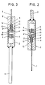
- the gang saw blade has a row of holes running parallel to these in the region of the end edges and consisting of holes 5 which are at the same, narrow distance from one another.
- the strips 4 start from the toothed edge 1 ′′′ of the saw blade.
- the length ratio of bar to frame saw blade width is approximately 1: 2.
- each gang saw fishing box 2 has a stop 7 at the end of the saw passage gap 6 thereof.
- the end face 8 of one of the strips 4 arranged in pairs occurs in the insertion direction ⁇ ligating.
- the distance of the stop 7 from the front edge 9 of the frame saw fishing box 2 corresponds approximately to the length of the strips 4.
- the gang saw fishing box 2 has a greater width in its lower region facing the center of the saw blade (upper end of the saw blade 1 ') than in its region facing the shaft 3.
- the widening zone extends in the direction of the saw blade rear edge 1 ⁇ and is designated by 10. The latter forms wing-like projections.
- the widening level St coincides with the height of the counter surface 2 '.
- the support surfaces 4 'of the strips 4 and the counter surfaces 2' of the fishing box 2 are undercut in opposite directions, so that a spreading tendency of the pocket walls forming the fishing box is effectively prevented. Rather, a Kratt component that contracts the pocket walls under load occurs.
- This is also used in the sense of supporting the attachment of the strips 4, for which the strips 4 are stepped in such a way that a wing-like protruding strip section 11 resting on the broad sides of the saw blade remains, which protrudes into a corresponding recess 12 in the saw passage gap 6.
- the strip section 11 is subjected to pressure in the direction of the saw blade broad surface and is thus clamped.
- the screw pin 13 is further flanked by two centering pins 16, which, also penetrating the holes 5 of the row of holes, also define the strips 4.
- the fishing box itself secures the axial position of the centering pin 16 with its pocket inner walls, which can also have edge notches.
Landscapes
- Life Sciences & Earth Sciences (AREA)
- Engineering & Computer Science (AREA)
- Mechanical Engineering (AREA)
- Wood Science & Technology (AREA)
- Forests & Forestry (AREA)
- Knives (AREA)
- Fishing Rods (AREA)
- Nonmetal Cutting Devices (AREA)
- Sawing (AREA)
Claims (4)
Priority Applications (1)
| Application Number | Priority Date | Filing Date | Title |
|---|---|---|---|
| AT82102562T ATE13988T1 (de) | 1981-04-04 | 1982-03-26 | Gattersaegenangel mit gattersaegenblatt. |
Applications Claiming Priority (2)
| Application Number | Priority Date | Filing Date | Title |
|---|---|---|---|
| DE19813113647 DE3113647A1 (de) | 1981-04-04 | 1981-04-04 | Gattersaegenangel mit gattersaegenblatt |
| DE3113647 | 1981-04-04 |
Publications (4)
| Publication Number | Publication Date |
|---|---|
| EP0062260A2 EP0062260A2 (fr) | 1982-10-13 |
| EP0062260A3 EP0062260A3 (en) | 1983-05-04 |
| EP0062260B1 EP0062260B1 (fr) | 1985-06-26 |
| EP0062260B2 true EP0062260B2 (fr) | 1991-03-20 |
Family
ID=6129346
Family Applications (1)
| Application Number | Title | Priority Date | Filing Date |
|---|---|---|---|
| EP82102562A Expired - Lifetime EP0062260B2 (fr) | 1981-04-04 | 1982-03-26 | Chope de syspension avec une lame de scie alternative |
Country Status (3)
| Country | Link |
|---|---|
| EP (1) | EP0062260B2 (fr) |
| AT (1) | ATE13988T1 (fr) |
| DE (2) | DE3113647A1 (fr) |
Families Citing this family (1)
| Publication number | Priority date | Publication date | Assignee | Title |
|---|---|---|---|---|
| DE3601942A1 (de) * | 1986-01-23 | 1987-07-30 | Schmahl F A Jun | Saegeblatt mit doppelter lochreihe |
Family Cites Families (6)
| Publication number | Priority date | Publication date | Assignee | Title |
|---|---|---|---|---|
| DE182790C (fr) * | ||||
| DE1628879B2 (de) * | 1967-06-10 | 1975-07-03 | Fa. Richard Jansen, 5630 Remscheid | Sägeangel zum Einspannen von Sägeblättern in Gatterrahmen von Gattersägen |
| AT279138B (de) * | 1968-01-12 | 1970-02-25 | Miller Gmbh Martin | Sägeblatt für Gattersägen |
| AT297304B (de) * | 1968-06-24 | 1972-03-27 | Miller Gmbh Martin | Sägeblatt für Gattersägen |
| DE2118450C3 (de) * | 1971-04-16 | 1982-10-07 | Fa. Richard Jansen, 5630 Remscheid | Sägeangel für Sägeblätter in Gatterrahmen |
| DE2844329A1 (de) * | 1978-10-11 | 1980-04-30 | Felde Richard Fa | Einschubangel zum einspannen von saegeblaettern in gatterrahmen von gattersaegen |
-
1981
- 1981-04-04 DE DE19813113647 patent/DE3113647A1/de active Granted
-
1982
- 1982-03-26 EP EP82102562A patent/EP0062260B2/fr not_active Expired - Lifetime
- 1982-03-26 DE DE8282102562T patent/DE3264393D1/de not_active Expired
- 1982-03-26 AT AT82102562T patent/ATE13988T1/de active
Also Published As
| Publication number | Publication date |
|---|---|
| EP0062260B1 (fr) | 1985-06-26 |
| EP0062260A2 (fr) | 1982-10-13 |
| ATE13988T1 (de) | 1985-07-15 |
| DE3113647A1 (de) | 1982-10-21 |
| DE3264393D1 (en) | 1985-08-01 |
| DE3113647C2 (fr) | 1989-02-09 |
| EP0062260A3 (en) | 1983-05-04 |
Similar Documents
| Publication | Publication Date | Title |
|---|---|---|
| DE2411759C3 (de) | Schneidwerkzeug für die spanabhebende Bearbeitung | |
| CH630838A5 (de) | Vorrichtung zur halterung und zum vorschub eines werkstueckes gegen ein rotierendes schneidwerkzeug. | |
| EP0510351A2 (fr) | Outil d'enfoncement d'attaches | |
| DE2848554A1 (de) | Stanzmesser | |
| EP0062260B2 (fr) | Chope de syspension avec une lame de scie alternative | |
| DE69210743T2 (de) | Dichtungsschürze für die Laderinne eines Bandförderers | |
| DE19855711C2 (de) | Vorrichtung zur Befestigung von Wirkelementen an der Barre einer Kettenwirkmaschine | |
| DE2514943C2 (de) | Werkzeughalter | |
| DE1178469B (de) | Magnetkopfanordnung | |
| DE20100550U1 (de) | Schneidzahnanordnung | |
| DE2042509B2 (de) | Vorrichtung zur Befestigung von oberen Teilstücken an Aufnahmeschienen | |
| DE2915347C2 (de) | Abstandshalter | |
| DE3121109C2 (fr) | ||
| DE9401887U1 (de) | Halteelement zur Befestigung eines Bespannungselementes eines Sitz- oder Liegemöbels | |
| EP0241743A2 (fr) | Métier à tricoter rectiligne | |
| DE7714696U1 (de) | Messer zum einlagigen schneiden von papierblaettern | |
| DE3312662C1 (de) | Gattersägenangel | |
| DE2050263C3 (de) | Webschützen | |
| DE905840C (de) | Schraubzwinge | |
| DE677542C (de) | Befestigung der Matrizenfuehrungsdraehte von Matrizensetz- und Zeilengiessmaschinen | |
| DE1535904C (de) | Webschaft | |
| DE1535904B1 (de) | Webschaft | |
| EP0292681B1 (fr) | Chape de suspension de scie alternative | |
| DE2832968A1 (de) | Vorrichtung zum befestigen eines nadelstreifens am tragelement bei kettenstreckwerken, kaemm-maschinen u.dgl. | |
| CH367953A (de) | Vorrichtung zur lösbaren Befestigung einer quer abstehenden Stütze an einem mit Befestigungslöchern versehenen Träger |
Legal Events
| Date | Code | Title | Description |
|---|---|---|---|
| PUAI | Public reference made under article 153(3) epc to a published international application that has entered the european phase |
Free format text: ORIGINAL CODE: 0009012 |
|
| AK | Designated contracting states |
Designated state(s): AT CH DE FR |
|
| PUAL | Search report despatched |
Free format text: ORIGINAL CODE: 0009013 |
|
| 17P | Request for examination filed |
Effective date: 19821220 |
|
| AK | Designated contracting states |
Designated state(s): AT CH DE FR LI |
|
| GRAA | (expected) grant |
Free format text: ORIGINAL CODE: 0009210 |
|
| AK | Designated contracting states |
Designated state(s): AT CH DE FR LI |
|
| REF | Corresponds to: |
Ref document number: 13988 Country of ref document: AT Date of ref document: 19850715 Kind code of ref document: T |
|
| REF | Corresponds to: |
Ref document number: 3264393 Country of ref document: DE Date of ref document: 19850801 |
|
| ET | Fr: translation filed | ||
| PLBI | Opposition filed |
Free format text: ORIGINAL CODE: 0009260 |
|
| 26 | Opposition filed |
Opponent name: THOERESS SAEGENPRODUKTION GESELLSCHAFT M.B.H. Effective date: 19860326 |
|
| PUAH | Patent maintained in amended form |
Free format text: ORIGINAL CODE: 0009272 |
|
| STAA | Information on the status of an ep patent application or granted ep patent |
Free format text: STATUS: PATENT MAINTAINED AS AMENDED |
|
| 27A | Patent maintained in amended form |
Effective date: 19910320 |
|
| AK | Designated contracting states |
Kind code of ref document: B2 Designated state(s): AT CH DE FR LI |
|
| ET3 | Fr: translation filed ** decision concerning opposition | ||
| REG | Reference to a national code |
Ref country code: CH Ref legal event code: AEN |
|
| PGFP | Annual fee paid to national office [announced via postgrant information from national office to epo] |
Ref country code: DE Payment date: 20001229 Year of fee payment: 20 |
|
| PGFP | Annual fee paid to national office [announced via postgrant information from national office to epo] |
Ref country code: AT Payment date: 20010212 Year of fee payment: 20 |
|
| PGFP | Annual fee paid to national office [announced via postgrant information from national office to epo] |
Ref country code: FR Payment date: 20010213 Year of fee payment: 20 Ref country code: CH Payment date: 20010213 Year of fee payment: 20 |
|
| PG25 | Lapsed in a contracting state [announced via postgrant information from national office to epo] |
Ref country code: LI Free format text: LAPSE BECAUSE OF EXPIRATION OF PROTECTION Effective date: 20020325 Ref country code: CH Free format text: LAPSE BECAUSE OF EXPIRATION OF PROTECTION Effective date: 20020325 |
|
| PG25 | Lapsed in a contracting state [announced via postgrant information from national office to epo] |
Ref country code: AT Free format text: LAPSE BECAUSE OF EXPIRATION OF PROTECTION Effective date: 20020326 |
|
| REG | Reference to a national code |
Ref country code: CH Ref legal event code: PL |