EP0062271A1 - Dispositif de fixation - Google Patents
Dispositif de fixation Download PDFInfo
- Publication number
- EP0062271A1 EP0062271A1 EP19820102619 EP82102619A EP0062271A1 EP 0062271 A1 EP0062271 A1 EP 0062271A1 EP 19820102619 EP19820102619 EP 19820102619 EP 82102619 A EP82102619 A EP 82102619A EP 0062271 A1 EP0062271 A1 EP 0062271A1
- Authority
- EP
- European Patent Office
- Prior art keywords
- fastening element
- bead
- workpiece
- screw
- element according
- Prior art date
- Legal status (The legal status is an assumption and is not a legal conclusion. Google has not performed a legal analysis and makes no representation as to the accuracy of the status listed.)
- Granted
Links
- 239000011324 bead Substances 0.000 claims abstract description 53
- 238000006073 displacement reaction Methods 0.000 description 18
- 230000000694 effects Effects 0.000 description 6
- 239000000463 material Substances 0.000 description 5
- 238000010586 diagram Methods 0.000 description 2
- 241000872198 Serjania polyphylla Species 0.000 description 1
- 230000006978 adaptation Effects 0.000 description 1
- 238000004026 adhesive bonding Methods 0.000 description 1
- 238000005452 bending Methods 0.000 description 1
- 230000015572 biosynthetic process Effects 0.000 description 1
- 229910052793 cadmium Inorganic materials 0.000 description 1
- 230000001427 coherent effect Effects 0.000 description 1
- 238000007373 indentation Methods 0.000 description 1
- 238000005461 lubrication Methods 0.000 description 1
- 230000035515 penetration Effects 0.000 description 1
- 230000002093 peripheral effect Effects 0.000 description 1
Images
Classifications
-
- F—MECHANICAL ENGINEERING; LIGHTING; HEATING; WEAPONS; BLASTING
- F16—ENGINEERING ELEMENTS AND UNITS; GENERAL MEASURES FOR PRODUCING AND MAINTAINING EFFECTIVE FUNCTIONING OF MACHINES OR INSTALLATIONS; THERMAL INSULATION IN GENERAL
- F16B—DEVICES FOR FASTENING OR SECURING CONSTRUCTIONAL ELEMENTS OR MACHINE PARTS TOGETHER, e.g. NAILS, BOLTS, CIRCLIPS, CLAMPS, CLIPS OR WEDGES; JOINTS OR JOINTING
- F16B39/00—Locking of screws, bolts or nuts
- F16B39/22—Locking of screws, bolts or nuts in which the locking takes place during screwing down or tightening
- F16B39/28—Locking of screws, bolts or nuts in which the locking takes place during screwing down or tightening by special members on, or shape of, the nut or bolt
- F16B39/282—Locking by means of special shape of work-engaging surfaces, e.g. notched or toothed nuts
-
- F—MECHANICAL ENGINEERING; LIGHTING; HEATING; WEAPONS; BLASTING
- F16—ENGINEERING ELEMENTS AND UNITS; GENERAL MEASURES FOR PRODUCING AND MAINTAINING EFFECTIVE FUNCTIONING OF MACHINES OR INSTALLATIONS; THERMAL INSULATION IN GENERAL
- F16B—DEVICES FOR FASTENING OR SECURING CONSTRUCTIONAL ELEMENTS OR MACHINE PARTS TOGETHER, e.g. NAILS, BOLTS, CIRCLIPS, CLAMPS, CLIPS OR WEDGES; JOINTS OR JOINTING
- F16B39/00—Locking of screws, bolts or nuts
- F16B39/22—Locking of screws, bolts or nuts in which the locking takes place during screwing down or tightening
- F16B39/24—Locking of screws, bolts or nuts in which the locking takes place during screwing down or tightening by means of washers, spring washers, or resilient plates that lock against the object
Definitions
- the invention relates to a fastening element with a surface that comes to bear on a workpiece surface or another fastening element under contact pressure and runs approximately perpendicular to the central axis thereof, wherein at least one surface of the fastening element that comes to rest on a workpiece or another fastening element has at least one circular arc extending bead or bead section aligned with the center axis of the fastening element.
- a nut for mounting on a screw guided through a workpiece on the surface directed against the workpiece has concentrically or spiraling ramps which are directed against the workpiece to be screwed. These ramps are located adjacent to the bore in the nut, the higher ends of the ramps being radially closer to the bore than the tapered ends. The inclined incline of the ramps is opposite to the thread pitch of the screw.
- the invention has therefore set itself the task of creating a fastener with which a radial Displacement between the contact surfaces can be prevented in order to achieve a secure solution.
- This bead which can be arranged, for example, on the underside of the screw head, on a surface of a nut or on two surfaces of a washer, is pressed into the adjacent workpiece or the adjacent fastening element, so that an effective securing against radial displacement of the screw head or the nut compared to the workpiece to be clamped.
- the feared tipping moment or a relative movement under the headrest can no longer occur.
- the arrangement of such a bead forms a groove in the opposite part, so that in addition to the non-positive connection due to the tightening torque, there is also a positive connection and a positive contact between the screw head or nut and the workpiece, which, however, only move into radial direction prevented.
- a fastening element designed according to the invention By means of a fastening element designed according to the invention, rotation is readily possible.
- the torque for tightening the nut is only changed for the bead until the bead has completely penetrated the workpiece.
- the design of a fastening element according to the invention is therefore particularly advantageous because it enables the tightening torque of a screw connection to be precisely controlled, even without the use of complicated, torque-limited screw-in tools.
- the protruding bulge is pressed into the opposite surface after a corresponding increase in the tightening torque, and after the bulge has completely penetrated through the now large surface, there is a noticeable difference when tightening one Bolted connection is created, whereby an adaptation to different yield stresses of the bolts can be achieved.
- the arrangement according to the invention means that no additional measures have to be taken which increase the loosening torque. If there can be no radial relative movement between the contact surfaces, the screws do not come loose, so that the frictional forces between the flat, abutting surfaces are sufficient.
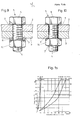
- FIG. 1 shows a cross section through a transversely stressed screw connection
- 1a shows a diagram relating to the limit displacement for rigid screws
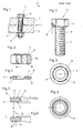
- Figure 2 is a side view of a screw, with part of the head shown cut away.
- Figure 3 shows a nut partially cut.
- 4 shows a cross section through a washer.
- 5 shows a plan view of a washer with a special embodiment of the bead;
- 6 is a plan view of a washer with two coaxial beads.
- Figures 7 and 8 cross sections through washers with different embodiments. 9 and 10, two screwing examples in partial section.
- Fig. 1 shows a prestressed screw connection, which is stressed by transverse forces. If these transverse forces are sufficiently large to overcome the frictional engagement in the parting line 1 between the tensioned parts 2 and 3, ie if these prestressed parts move against one another, then the shaft 4 of the screw 5 is deformed in the manner shown. If this movement becomes so great that the bending resistance of the screw shaft 4 is overcome, then the screw head 6 also slides and the courage occurs ter 14 in the radial direction with respect to the braced parts 2 and 3. Thus, a slip occurs under the screw head and under the nut, so that the self-locking of the screw connection is released. The screw connection then turns off automatically, even if the known designs of measures increasing the loosening torque are provided.
- Fig. 1a shows the experimentally determined limit displacement s for rigid screws M 10.
- the influence of the clamping length, that is, the screw length, and the pretensioning force can be seen very clearly here.
- the influence of the coefficient of friction on the headrest - cadmium-coated or black with MoS 2 lubrication - can also be clearly seen.
- the curve for the limit shift s divides this preload-limit shift diagram into two fields. To the left of the curve is the area in which an additional securing of the screw connection is not necessary because the limit shift s is not exceeded and therefore there is no fear of automatic loosening. To the right of the curve is the turning area.
- the limit shift is exceeded. that is, slip occurs under the screw head and under the nut, the self-locking is released and the screw connection turns off automatically. This subsequent loosening can be influenced by the use of suitable screw locks, but cannot be prevented.
- the slippage between the screw head or the nut and the parts to be screwed that is, a radial displacement of the screw head, the nut or the washer with respect to the workpiece, is to be prevented.
- FIG. 2 shows an embodiment in the form of a screw 5, which consists of a screw head 6 and the shaft 4.
- an annular bead 7 is provided which is aligned with the central axis 9 of the screw 5.
- Such an embodiment is used when the surface 8 comes into direct contact with the workpiece to be screwed. No washer is needed here.
- the bead digs into the surface of the workpiece to be screwed, so that a displacement of the screw head relative to this workpiece surface is excluded from the outset. This will not loosen the screw connection.
- the strength of the bead must be so great that the counter material can be deformed. The necessary strength values for the different screw connections are therefore taken into account depending on the pairing of the materials.
- the bead 7 has boundary surfaces running in a straight line in cross section, a triangular cross section being specifically provided here.
- this bead it is also conceivable for this bead to be rectangular or trapezoidal in cross-section or else to have curved boundary surfaces, the indentation force and the holding force being adjustable depending on the cross-sectional shape.
- the bead thus forms a circular arc of uniform diameter, preferably extending over the entire circumference, the center of which lies in the central axis of the fastening element.
- Fig. 3 shows a nut 14, which has a bead 7 on one surface 8, which produces the same effect as is the case with the screw 5.
- a nut 14 it would also be conceivable to provide a bead 7 on each of the two opposite surfaces 8 and 10.
- FIG. 4 shows an embodiment of a fastening element in the form of a washer 11.
- beads 7 are also provided on the surfaces facing away from one another.
- the formation of the features according to the invention on a washer 11 is particularly expedient because only one such fastening element then has to be formed in this way.
- the beads 7 on the washer 11 thus dig into the upper surface of the screw head 6 and also into the workpiece to be screwed accordingly, so that the same effect is achieved as when screwing the screw 5, which is equipped with a corresponding bead 7 .
- the annular bead 7 viewed in the circumferential direction, is divided into two or more arcuate sections 7 '.
- the bead 7 is cut into the corresponding surface, since the respective beginning of the corresponding section 7 'exerts a cutting effect. If, on the other hand, the bead 7 runs continuously, only a pressing into the opposite surface takes place. In such an embodiment, they may lie between sections 7 ' However, the areas should only be very small so that the flawless effect of securing against radial advancement between the contact surfaces is not reduced or is even lost.
- two coaxially extending beads 7 are provided, with such a measure increasing the security against displacement of the screw head or the nut.
- the surface 8 of the fastening element in the area 12, that is to say inside the bead 7, is set back by a wet A with respect to the area 13 of the surface 8, which lies outside the bead 7.
- This wet setback is very small and expediently also smaller than the height of the bead 7. This ensures that the fastening elements are securely supported on the outer peripheral edges of each other and on the workpiece, so that there is never a tilting movement of the screw head or Mother can come.
- the diameters D 1 and D 2 of the annular beads 7 on the surfaces 8 facing away from one another are of different sizes, so that these beads 7 are offset from one another.
- the present invention provides a screw lock with structurally very simple measures, which prevents a screw connection from being loosened even in the event of an alternating load, without special design measures having to be taken to increase the loosening torque.
Landscapes
- Engineering & Computer Science (AREA)
- General Engineering & Computer Science (AREA)
- Mechanical Engineering (AREA)
- Bolts, Nuts, And Washers (AREA)
Applications Claiming Priority (2)
| Application Number | Priority Date | Filing Date | Title |
|---|---|---|---|
| AT0157681A AT370217B (de) | 1981-04-06 | 1981-04-06 | Befestigungselement |
| AT1576/81 | 1981-04-06 |
Publications (2)
| Publication Number | Publication Date |
|---|---|
| EP0062271A1 true EP0062271A1 (fr) | 1982-10-13 |
| EP0062271B1 EP0062271B1 (fr) | 1985-06-19 |
Family
ID=3516402
Family Applications (1)
| Application Number | Title | Priority Date | Filing Date |
|---|---|---|---|
| EP19820102619 Expired EP0062271B1 (fr) | 1981-04-06 | 1982-03-29 | Dispositif de fixation |
Country Status (3)
| Country | Link |
|---|---|
| EP (1) | EP0062271B1 (fr) |
| AT (1) | AT370217B (fr) |
| DE (1) | DE3264234D1 (fr) |
Cited By (7)
| Publication number | Priority date | Publication date | Assignee | Title |
|---|---|---|---|---|
| EP0679813A1 (fr) * | 1994-04-27 | 1995-11-02 | Automobiles Peugeot | Organe de fixation mécanique de deux éléments l'un à l'autre, notamment pour la fixation d'un carter de direction à un support de direction |
| DE19620794A1 (de) * | 1996-05-23 | 1997-11-27 | Man Nutzfahrzeuge Ag | Abdichtung eines Schraubenkopfes |
| EP1900619A1 (fr) * | 2006-09-18 | 2008-03-19 | Jost-Werke GmbH & Co. KG | Agencement d'un support de palier sur une plaque de montage |
| DE102008017474A1 (de) | 2008-04-03 | 2009-10-08 | Heinrich Gillet Gmbh | Befestigungsmittel und Baugruppe mit dem Befestigungsmittel |
| WO2011038930A1 (fr) | 2009-10-01 | 2011-04-07 | Heinrich Gillet Gmbh | Module avec moyen de sécurité |
| EP4201793A1 (fr) * | 2021-12-23 | 2023-06-28 | JOST-Werke Deutschland GmbH | Sellette d'attelage et sellette d'attelage |
| CN118049428A (zh) * | 2024-04-07 | 2024-05-17 | 福安奥展实业有限公司 | 一种新能源汽车电池用锁紧螺丝 |
Families Citing this family (3)
| Publication number | Priority date | Publication date | Assignee | Title |
|---|---|---|---|---|
| US4498825A (en) * | 1982-09-27 | 1985-02-12 | Russell, Burdsall & Ward Corporation | Load indicating flange |
| DE10327349B4 (de) * | 2003-06-16 | 2014-08-28 | FRÖTEK Vermögensverwaltung GmbH | Batterieverbinder-Anordnung |
| CN107339310A (zh) * | 2017-06-30 | 2017-11-10 | 上海应谱科技有限公司 | 一种智能紧固件 |
Citations (7)
| Publication number | Priority date | Publication date | Assignee | Title |
|---|---|---|---|---|
| US2096040A (en) * | 1935-02-11 | 1937-10-19 | Richard T Hosking | Lock nut |
| DE1978440U (de) * | 1963-04-19 | 1968-02-08 | Guenter Uhl | Schraubensicherung mit dichtwirkung. |
| US3491630A (en) * | 1968-07-08 | 1970-01-27 | Lloyd L Mielke | Bolt,nut and washer combination |
| US3531850A (en) * | 1967-01-30 | 1970-10-06 | Francois Durand | Method of assembling a friable member and a member of plastically deformable material |
| DE1750063B1 (de) * | 1967-03-28 | 1971-04-22 | Illinois Tool Works | Selbstsicherndes mit gewinde versehenes befestigungselement |
| FR2219699A6 (fr) * | 1972-10-25 | 1974-09-20 | Launay Pierre | |
| DE2845072A1 (de) * | 1978-10-16 | 1980-04-30 | Heinrichs & Co Kg Schrauben Un | Einschraubzapfen |
-
1981
- 1981-04-06 AT AT0157681A patent/AT370217B/de not_active IP Right Cessation
-
1982
- 1982-03-29 DE DE8282102619T patent/DE3264234D1/de not_active Expired
- 1982-03-29 EP EP19820102619 patent/EP0062271B1/fr not_active Expired
Patent Citations (7)
| Publication number | Priority date | Publication date | Assignee | Title |
|---|---|---|---|---|
| US2096040A (en) * | 1935-02-11 | 1937-10-19 | Richard T Hosking | Lock nut |
| DE1978440U (de) * | 1963-04-19 | 1968-02-08 | Guenter Uhl | Schraubensicherung mit dichtwirkung. |
| US3531850A (en) * | 1967-01-30 | 1970-10-06 | Francois Durand | Method of assembling a friable member and a member of plastically deformable material |
| DE1750063B1 (de) * | 1967-03-28 | 1971-04-22 | Illinois Tool Works | Selbstsicherndes mit gewinde versehenes befestigungselement |
| US3491630A (en) * | 1968-07-08 | 1970-01-27 | Lloyd L Mielke | Bolt,nut and washer combination |
| FR2219699A6 (fr) * | 1972-10-25 | 1974-09-20 | Launay Pierre | |
| DE2845072A1 (de) * | 1978-10-16 | 1980-04-30 | Heinrichs & Co Kg Schrauben Un | Einschraubzapfen |
Cited By (12)
| Publication number | Priority date | Publication date | Assignee | Title |
|---|---|---|---|---|
| EP0679813A1 (fr) * | 1994-04-27 | 1995-11-02 | Automobiles Peugeot | Organe de fixation mécanique de deux éléments l'un à l'autre, notamment pour la fixation d'un carter de direction à un support de direction |
| FR2719348A1 (fr) * | 1994-04-27 | 1995-11-03 | Peugeot | Organe de fixation mécanique de deux éléments l'un à l'autre, notamment pour la fixation d'un carter de direction à un support de direction. |
| DE19620794A1 (de) * | 1996-05-23 | 1997-11-27 | Man Nutzfahrzeuge Ag | Abdichtung eines Schraubenkopfes |
| EP1900619A1 (fr) * | 2006-09-18 | 2008-03-19 | Jost-Werke GmbH & Co. KG | Agencement d'un support de palier sur une plaque de montage |
| US7950152B2 (en) | 2006-09-18 | 2011-05-31 | Jost-Werke Gmbh | Method of mounting a bearing block on a mounting plate |
| DE102008017474A1 (de) | 2008-04-03 | 2009-10-08 | Heinrich Gillet Gmbh | Befestigungsmittel und Baugruppe mit dem Befestigungsmittel |
| WO2011038930A1 (fr) | 2009-10-01 | 2011-04-07 | Heinrich Gillet Gmbh | Module avec moyen de sécurité |
| DE102009043685A1 (de) | 2009-10-01 | 2011-04-14 | Heinrich Gillet Gmbh | Baugruppe mit Sicherungsmittel |
| DE102009043685B4 (de) * | 2009-10-01 | 2016-09-15 | Tenneco Gmbh | Baugruppe mit Sicherungsmittel |
| EP4201793A1 (fr) * | 2021-12-23 | 2023-06-28 | JOST-Werke Deutschland GmbH | Sellette d'attelage et sellette d'attelage |
| US12589816B2 (en) | 2021-12-23 | 2026-03-31 | Jost-Werke Deutschland Gmbh | Fifth wheel plate and fifth wheel coupling |
| CN118049428A (zh) * | 2024-04-07 | 2024-05-17 | 福安奥展实业有限公司 | 一种新能源汽车电池用锁紧螺丝 |
Also Published As
| Publication number | Publication date |
|---|---|
| ATA157681A (de) | 1982-07-15 |
| AT370217B (de) | 1983-03-10 |
| DE3264234D1 (en) | 1985-07-25 |
| EP0062271B1 (fr) | 1985-06-19 |
Similar Documents
| Publication | Publication Date | Title |
|---|---|---|
| EP0370212B1 (fr) | Ecrou avec anneau de serrage | |
| DE10034748B4 (de) | Lösbares Verbindungselement für ein Fahrzeugrad, mit einem Schraubteil und einem Stützring | |
| DE69304301T2 (de) | Verbindungselement zwischen zwei Bauteilen | |
| EP0053089B1 (fr) | Bride d'attache | |
| DE10048913B4 (de) | Lösbares Verbindungselement für ein Bauteil, mit einem Schraubteil und einem Sicherungsring | |
| EP0354363A2 (fr) | Dispositif de blocage à douille taraudée | |
| DE3640668A1 (de) | Doppelmutter | |
| DE1750063B1 (de) | Selbstsicherndes mit gewinde versehenes befestigungselement | |
| DE2649077A1 (de) | Konische federnde unterlagscheibe | |
| DE2927366A1 (de) | Befestigungselement mit gewinde | |
| EP0854791B1 (fr) | Dispositif pour fixer de maniere amovible une roue supplementaire sur la roue d'un vehicule | |
| DE3917192A1 (de) | Befestigungsvorrichtung | |
| DE20206373U1 (de) | Selbstsichernde Befestigungseinrichtung | |
| DE2854676A1 (de) | Schneckengewindeschelle | |
| DE3700422C2 (fr) | ||
| EP0062271A1 (fr) | Dispositif de fixation | |
| DE8908545U1 (de) | Befestigungselement, insbesondere für eine Kugel-Gewindespindel | |
| DE19945255A1 (de) | Radlagerung, insbesondere für nichtangetriebene Fahrzeugachsen | |
| DE10253642A1 (de) | Scheibenbremse, insbesondere für ein Nutzfahrzeug | |
| DE3884571T2 (de) | Lenksäulenverbindung. | |
| EP4416399B1 (fr) | Contre-écrou comprenant un élément de sécurité | |
| DE2660403C2 (de) | Befestigungsanordnung zur Montage einer Reifenfelge an Radkranzteilen | |
| EP0357985B1 (fr) | Connexion entre deux barres profilées qui se couvrent ou s'alignent sous un angle | |
| DE2443013A1 (de) | Befestigungselement | |
| DE2020782A1 (de) | Sicherungsmutter |
Legal Events
| Date | Code | Title | Description |
|---|---|---|---|
| PUAI | Public reference made under article 153(3) epc to a published international application that has entered the european phase |
Free format text: ORIGINAL CODE: 0009012 |
|
| AK | Designated contracting states |
Designated state(s): BE CH DE FR GB IT LU NL SE |
|
| 17P | Request for examination filed |
Effective date: 19830402 |
|
| ITF | It: translation for a ep patent filed | ||
| GRAA | (expected) grant |
Free format text: ORIGINAL CODE: 0009210 |
|
| AK | Designated contracting states |
Designated state(s): BE CH DE FR GB IT LI LU NL SE |
|
| REF | Corresponds to: |
Ref document number: 3264234 Country of ref document: DE Date of ref document: 19850725 |
|
| ET | Fr: translation filed | ||
| PG25 | Lapsed in a contracting state [announced via postgrant information from national office to epo] |
Ref country code: LU Free format text: LAPSE BECAUSE OF NON-PAYMENT OF DUE FEES Effective date: 19860331 |
|
| PGFP | Annual fee paid to national office [announced via postgrant information from national office to epo] |
Ref country code: LU Payment date: 19860404 Year of fee payment: 5 |
|
| PLBE | No opposition filed within time limit |
Free format text: ORIGINAL CODE: 0009261 |
|
| STAA | Information on the status of an ep patent application or granted ep patent |
Free format text: STATUS: NO OPPOSITION FILED WITHIN TIME LIMIT |
|
| 26N | No opposition filed | ||
| PGFP | Annual fee paid to national office [announced via postgrant information from national office to epo] |
Ref country code: NL Payment date: 19870331 Year of fee payment: 6 |
|
| PG25 | Lapsed in a contracting state [announced via postgrant information from national office to epo] |
Ref country code: GB Effective date: 19890329 |
|
| PG25 | Lapsed in a contracting state [announced via postgrant information from national office to epo] |
Ref country code: SE Effective date: 19890330 |
|
| PG25 | Lapsed in a contracting state [announced via postgrant information from national office to epo] |
Ref country code: LI Effective date: 19890331 Ref country code: CH Effective date: 19890331 Ref country code: BE Effective date: 19890331 |
|
| BERE | Be: lapsed |
Owner name: FINK HANS Effective date: 19890331 |
|
| PG25 | Lapsed in a contracting state [announced via postgrant information from national office to epo] |
Ref country code: NL Effective date: 19891001 |
|
| NLV4 | Nl: lapsed or anulled due to non-payment of the annual fee | ||
| GBPC | Gb: european patent ceased through non-payment of renewal fee | ||
| PG25 | Lapsed in a contracting state [announced via postgrant information from national office to epo] |
Ref country code: FR Free format text: LAPSE BECAUSE OF NON-PAYMENT OF DUE FEES Effective date: 19891130 |
|
| REG | Reference to a national code |
Ref country code: CH Ref legal event code: PL |
|
| PG25 | Lapsed in a contracting state [announced via postgrant information from national office to epo] |
Ref country code: DE Effective date: 19891201 |
|
| REG | Reference to a national code |
Ref country code: FR Ref legal event code: ST |
|
| EUG | Se: european patent has lapsed |
Ref document number: 82102619.2 Effective date: 19900124 |