EP0053089B1 - Bride d'attache - Google Patents
Bride d'attache Download PDFInfo
- Publication number
- EP0053089B1 EP0053089B1 EP81730075A EP81730075A EP0053089B1 EP 0053089 B1 EP0053089 B1 EP 0053089B1 EP 81730075 A EP81730075 A EP 81730075A EP 81730075 A EP81730075 A EP 81730075A EP 0053089 B1 EP0053089 B1 EP 0053089B1
- Authority
- EP
- European Patent Office
- Prior art keywords
- legs
- joint part
- teeth
- annular
- hanger
- Prior art date
- Legal status (The legal status is an assumption and is not a legal conclusion. Google has not performed a legal analysis and makes no representation as to the accuracy of the status listed.)
- Expired
Links
- 230000000295 complement effect Effects 0.000 claims 3
- 239000000463 material Substances 0.000 description 5
- 230000005540 biological transmission Effects 0.000 description 2
- 238000010586 diagram Methods 0.000 description 2
- 238000004049 embossing Methods 0.000 description 2
- 238000009413 insulation Methods 0.000 description 2
- 238000004519 manufacturing process Methods 0.000 description 2
- 101100482711 Caenorhabditis elegans gon-2 gene Proteins 0.000 description 1
- 241000701193 Mutellina purpurea Species 0.000 description 1
- 229910000831 Steel Inorganic materials 0.000 description 1
- 238000005452 bending Methods 0.000 description 1
- 238000010276 construction Methods 0.000 description 1
- 239000000356 contaminant Substances 0.000 description 1
- 230000008878 coupling Effects 0.000 description 1
- 238000010168 coupling process Methods 0.000 description 1
- 238000005859 coupling reaction Methods 0.000 description 1
- 230000001419 dependent effect Effects 0.000 description 1
- 239000002184 metal Substances 0.000 description 1
- 230000002787 reinforcement Effects 0.000 description 1
- 230000000630 rising effect Effects 0.000 description 1
- 239000010959 steel Substances 0.000 description 1
- 230000007704 transition Effects 0.000 description 1
Images


Classifications
-
- F—MECHANICAL ENGINEERING; LIGHTING; HEATING; WEAPONS; BLASTING
- F16—ENGINEERING ELEMENTS AND UNITS; GENERAL MEASURES FOR PRODUCING AND MAINTAINING EFFECTIVE FUNCTIONING OF MACHINES OR INSTALLATIONS; THERMAL INSULATION IN GENERAL
- F16L—PIPES; JOINTS OR FITTINGS FOR PIPES; SUPPORTS FOR PIPES, CABLES OR PROTECTIVE TUBING; MEANS FOR THERMAL INSULATION IN GENERAL
- F16L3/00—Supports for pipes, cables or protective tubing, e.g. hangers, holders, clamps, cleats, clips, brackets
- F16L3/08—Supports for pipes, cables or protective tubing, e.g. hangers, holders, clamps, cleats, clips, brackets substantially surrounding the pipe, cable or protective tubing
- F16L3/10—Supports for pipes, cables or protective tubing, e.g. hangers, holders, clamps, cleats, clips, brackets substantially surrounding the pipe, cable or protective tubing divided, i.e. with two members engaging the pipe, cable or protective tubing
- F16L3/11—Supports for pipes, cables or protective tubing, e.g. hangers, holders, clamps, cleats, clips, brackets substantially surrounding the pipe, cable or protective tubing divided, i.e. with two members engaging the pipe, cable or protective tubing and hanging from a pendant
-
- F—MECHANICAL ENGINEERING; LIGHTING; HEATING; WEAPONS; BLASTING
- F16—ENGINEERING ELEMENTS AND UNITS; GENERAL MEASURES FOR PRODUCING AND MAINTAINING EFFECTIVE FUNCTIONING OF MACHINES OR INSTALLATIONS; THERMAL INSULATION IN GENERAL
- F16L—PIPES; JOINTS OR FITTINGS FOR PIPES; SUPPORTS FOR PIPES, CABLES OR PROTECTIVE TUBING; MEANS FOR THERMAL INSULATION IN GENERAL
- F16L3/00—Supports for pipes, cables or protective tubing, e.g. hangers, holders, clamps, cleats, clips, brackets
- F16L3/16—Supports for pipes, cables or protective tubing, e.g. hangers, holders, clamps, cleats, clips, brackets with special provision allowing movement of the pipe
Definitions
- the invention is based on a pipe clamp according to the preamble of claims 1 to 3.
- DE-C-29 07 850 discloses such a pipe clamp with an optionally rigid or articulated connection part connected to the pipe clamp, but there are still disadvantages for both the manufacturer and the user of this known clamp.
- the connecting part also requires two pairs of contact surfaces in order to enable the rigid and movable connection of the connecting part to the clamp and also a through hole for the clamping screw for each pair of contact surfaces, which holds the connecting part together with the clamp legs.
- these holes are, especially where they intersect, the additional hole for holding the fastening part (e.g. threaded rod), which is perpendicular to the holes mentioned, has no space in the connecting part at this point. For these reasons, the connector becomes large and expensive.
- the purpose of the invention is to overcome these drawbacks.
- the connecting part has only one pair of contact surfaces.
- there are even two holes for the tensioning screws which can create space for the threaded hole of the fastening part (e.g. threaded rod).
- the connecting part becomes very small and symmetrical, which, in addition to saving material, enables cost-saving production on cold forming presses.
- the connecting part can snap into any practically required position in the case of a rigid connection with the clamp legs, and it can be fully rotated about the common axis of the screw bolts in the case of the movable connection.
- clamp legs can be made smaller in their outer dimensions, in particular the leg length, than in the known solution, which has significant assembly advantages for the user and additionally prevents the insulation of the pipe that the clamp legs protrude beyond the insulation.
- each tooth in the annular toothed surface transforms part of the force of the torque into tensile force on the screw bolt and thus increases the surface pressure and thus the frictional force on the inclined tooth surfaces, which are clamped on one another. This relieves the load on the teeth, which results from positive locking, by the frictional resistance that arises in the sum of the loaded oblique tooth surfaces.
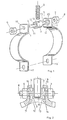
- legs 1, 2 which lie opposite one another. Both legs 1, 2 are each provided with a hole 19, 20 and each with an annular tooth surface 11, 14 around this hole.
- the pipe clamp or the pipe clamp halves are stamped parts made of sheet metal or strip material, in particular in the steel quality St 52.
- the connecting part 3 (Fig. 1) has two integrally formed threaded bolts 4, 5, which lie in an axis 8 and are provided with clamping nuts 6,7.
- the connecting part perpendicular to the threaded bolt axis 8 has a bore 10 with thread for the fastening part 9, the z. B. can be a threaded rod. This bore 10 is provided with a safeguard against loosening of the thread.
- Connecting part 3 and fastening part 9 can also form a unit.
- annular toothing surfaces 12, 13 are arranged around the screw bolts 4, 5, interact with the annular toothing surfaces 11, 14 of the clamp legs 1, 2.
- the connecting part 3 can, for. B. from QC 22, material 1.1152 according to DIN 1654.
- Tension cones 15, 16 originate from the tension nuts 6, 7, which build up in the material of the clamp legs 1, 2 and act on the annular toothed surfaces 11, 12, 13, 14.
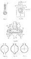
- the height of the individual teeth within an annular toothed surface can be the same everywhere (FIGS. 3a, 3b), even if the teeth become wider in the outer part of the toothed ring surface for geometric reasons (FIG. 3b).
- the inclined surfaces 24 of the teeth are then curved surfaces. In this case, the embossing of the annular toothed surfaces 11, 12, 13, 14 is facilitated since, with teeth of the same height, the material does not have to be compressed unevenly.
- 5a and 5b each show the view of an annular toothed surface with teeth which are inclined with respect to the radii and which are of the same height, namely with right-hand teeth and one with left-hand teeth, applied to an intermediate disk with toothed surfaces on both sides.
- Fig. 6 shows the surface of the cut teeth in an annular toothed surface with clockwise teeth and that of a second clockwise ring gear of the same type, which was placed on the first. Since these surfaces of the tooth tips lie in one plane and always overlap, it is clear that these toothings must slide smoothly on one another.
- At least 8 pairs of tooth tips lie on top of each other, at an angular distance of 50 gon, so that the coarse and fine toothing lying on top of each other cannot snap into place, but must slide on top of one another.
- the toothed ring surface 11 of the clamp leg 1 and the toothed ring surface 14 of the clamp leg 2 as well as the two toothed ring surfaces 12 and 13 of the connecting part 3 can now be provided, for example, with spiral toothings according to FIGS. 5a and 5b, which are mirror images, ie, the “direction of rotation” the spiral toothing is different. If one designates one direction of rotation with R for clockwise rotation and the other with L for counterclockwise rotation, the following embossings are possible on clamp legs 1, 2 and on connecting part 3:
- connection part 3 is rotated around the axis of the fastening bolt 9 by two right angles, the following application occurs:
- the movable connection is thus achieved with unchanged components.
- FIG. 7 shows a further example which is to be understood in the same way as FIG. 5 and its description.
- FIGS. 5a and 5b Such an intermediate disc can be clamped between the connecting part 3 and the clamp leg 1 or (and) clamp leg 2, whereby a different clamp diameter is realized.
- Such an washer impairs the double function of the clamp with a rigid or movable transition between the clamp legs 1, 2 and connecting part 3 in no way. With such washers, the pipe layer can help with small pipe diameter differences. This applies in particular to the case where the pipe clamp is made from one piece according to FIG. 11 b or FIG. 11 c.
- annular toothed contact surfaces can be used in a very simple manner only to achieve a rigid connection.
- a simple star toothing can be used, the teeth of which run straight to the center of the ring surface. If, in the case of a clamp consisting of two half-clamps according to FIG. 1, the two clamp legs are interchanged, so that the lower leg 17 of half-clamp 1 comes to rest on the annular toothed surface 12 of the connecting part 3 and leg 18 of half-clamp 2 on the annular toothed surface 13, then the mobile connection is established again.
- FIG. 9 shows a connecting part similar to DIN 444. with a firmly formed external thread bolt 37 as a fastening part.
- 10a and the associated FIG. 10b show a connecting part 27, in which a fastening part 37 ′ is received in an internal thread 38 of the connecting part 27.
- a screw 25 with nut 26 penetrates the connecting part. It presses over the nut 26 and head of the screw 25 and over the clamping cone 35, 36 the annular toothed surfaces 32, 33 of the connecting part 27 and the annular toothed surfaces 31, 34 of the clamp legs 28, 29.
- connection part 3 to be replaced by ordinary eyebolts according to DIN 444, which are provided with suitable star teeth, the part 37 provided with an external thread serving as a fastening part (FIG. 9).
- FIG. 11a which consists of two half-clamps
- a further fastening part 3 e.g. B. for coupling a further pipe clamp or for clamping the clamp halves on two sides, which, for. B. occurs in the case of falling and rising strands of pipelines.
Landscapes
- Engineering & Computer Science (AREA)
- General Engineering & Computer Science (AREA)
- Mechanical Engineering (AREA)
- Mutual Connection Of Rods And Tubes (AREA)
- Clamps And Clips (AREA)
- Supports For Pipes And Cables (AREA)
Claims (12)
Priority Applications (1)
| Application Number | Priority Date | Filing Date | Title |
|---|---|---|---|
| AT81730075T ATE8697T1 (de) | 1980-11-20 | 1981-08-19 | Rohrschelle. |
Applications Claiming Priority (2)
| Application Number | Priority Date | Filing Date | Title |
|---|---|---|---|
| DE3044008A DE3044008C1 (de) | 1980-11-20 | 1980-11-20 | Rohrschelle |
| DE3044008 | 1980-11-20 |
Publications (2)
| Publication Number | Publication Date |
|---|---|
| EP0053089A1 EP0053089A1 (fr) | 1982-06-02 |
| EP0053089B1 true EP0053089B1 (fr) | 1984-07-25 |
Family
ID=6117309
Family Applications (1)
| Application Number | Title | Priority Date | Filing Date |
|---|---|---|---|
| EP81730075A Expired EP0053089B1 (fr) | 1980-11-20 | 1981-08-19 | Bride d'attache |
Country Status (4)
| Country | Link |
|---|---|
| US (1) | US4407479A (fr) |
| EP (1) | EP0053089B1 (fr) |
| AT (1) | ATE8697T1 (fr) |
| DE (2) | DE3044008C1 (fr) |
Cited By (1)
| Publication number | Priority date | Publication date | Assignee | Title |
|---|---|---|---|---|
| DE3621484A1 (de) * | 1986-06-24 | 1988-01-21 | Hubert Combe | Rohrschelle zur wahlweisen pendelnden und starren aufhaengung von rohren |
Families Citing this family (25)
| Publication number | Priority date | Publication date | Assignee | Title |
|---|---|---|---|---|
| US4522000A (en) * | 1981-05-04 | 1985-06-11 | Barari Fred S | Earthquake safety support for transportable building |
| EP0115246A1 (fr) * | 1983-02-01 | 1984-08-08 | Hubert Combé | Collier de serrage |
| DE3326362C1 (de) * | 1983-07-21 | 1984-08-16 | Egon 5216 Niederkassel Striedelmeyer | Befestigungsschelle für Rohrleitungen wie Regenabfallrohre oder dgl. |
| EP0135698B1 (fr) * | 1983-07-21 | 1988-12-28 | Egon Striedelmeyer | Patte de fixation de tuyau |
| GB2165915A (en) * | 1984-08-03 | 1986-04-23 | Tustin & Smith Limited | Pipe support system |
| GB2337095B (en) * | 1996-03-04 | 2000-05-03 | British Gas Plc | Pipe clamp |
| DE19734556C1 (de) * | 1997-07-30 | 1998-12-24 | Junge Thomas | Anordnung zum Aufhängen einer Rohrleitung |
| US6102341A (en) * | 1998-12-31 | 2000-08-15 | Ball; Richard | Speed clip hanger bracket |
| US6598544B2 (en) * | 2001-05-17 | 2003-07-29 | Mity-Lite, Inc. | Locking mechanism for folding legs |
| US7107915B2 (en) * | 2001-05-17 | 2006-09-19 | Mity-Lite, Inc. | Locking mechanism for folding legs |
| USD489000S1 (en) | 2001-10-01 | 2004-04-27 | Warwick Hanger Co. | Bell type pipe hanger |
| USD486729S1 (en) | 2002-07-02 | 2004-02-17 | Warwick Hanger, Co. | Bell-type pipe hanger |
| AT414346B (de) * | 2003-09-05 | 2013-10-15 | Best On Bolt Gmbh | Sicherungselement zur sicherung von schraubenelementen |
| US7261256B2 (en) * | 2004-03-29 | 2007-08-28 | The Boeing Company | Variable-duct support assembly |
| US8454093B2 (en) | 2008-12-24 | 2013-06-04 | Mity-Lite, Inc. | Mesh chair with open-end hoop |
| US8038221B2 (en) | 2008-12-24 | 2011-10-18 | Mity-Lite, Inc. | Folding mesh chair with nesting hoops |
| US8317269B2 (en) | 2008-12-24 | 2012-11-27 | Mity-Lite, Inc. | Mesh stacking chair |
| US8322787B2 (en) | 2008-12-24 | 2012-12-04 | Mity-Lite, Inc. | Clamping joint for a chair |
| USD599127S1 (en) | 2009-04-13 | 2009-09-01 | Mity-Lite, Inc. | Mesh folding chair |
| ITTO20090584A1 (it) * | 2009-07-29 | 2011-01-30 | Dytech Dynamic Fluid Tech Spa | Fascetta portatubi |
| USD648554S1 (en) | 2009-11-04 | 2011-11-15 | Mity-Lite, Inc. | Mesh stacking chair |
| USD660612S1 (en) | 2010-11-16 | 2012-05-29 | Mity-Lite, Inc. | Mesh banquet chair |
| CN103899846B (zh) * | 2012-12-26 | 2016-03-30 | 中山市云创知识产权服务有限公司 | 线扣 |
| US10781944B2 (en) | 2018-09-27 | 2020-09-22 | Anvil International, Llc | Pipe clamp |
| PL132001U1 (pl) * | 2024-02-28 | 2024-07-15 | Dissera Spółka Z Ograniczoną Odpowiedzialnością | Obejma rurowa |
Family Cites Families (12)
| Publication number | Priority date | Publication date | Assignee | Title |
|---|---|---|---|---|
| US2375513A (en) * | 1943-09-30 | 1945-05-08 | William F Bach | Pipe hanger system |
| DE813333C (de) * | 1950-02-16 | 1951-09-10 | Ermeto G M B H | Einrichtung zum kraftschluessigen und formschluessigen Zusammen-spannen zweier Konstruktionselemente |
| US2780429A (en) * | 1953-03-24 | 1957-02-05 | Vincent P Vanier | Pipe hanger |
| DE1704304U (de) * | 1955-01-24 | 1955-08-11 | Ernst Schmidt | Rastenscheiben-drehgelenkverbindung, insbesondere fuer klappmoebel. |
| US3077218A (en) * | 1958-09-02 | 1963-02-12 | Schnorr Adolf Kg | Dish-spring lock-washers |
| DE1852979U (de) * | 1962-03-20 | 1962-06-07 | Westf Textilwerk Kock & Hunger | Rohrgestaenge fuer ein zelt, eine zelthuette od. dgl. |
| US3276172A (en) * | 1963-08-06 | 1966-10-04 | Goetaverken Ab | Means for detachably connecting partition walls |
| US3223371A (en) * | 1963-10-31 | 1965-12-14 | Fred J Miller | Bracket for supporting rails |
| DE1984835U (de) * | 1967-12-29 | 1968-05-02 | Ver Leichtmetallwerke Gmbh | Eckwinkelverbindungsvorrichtung fuer profile in verschiedenen gradeinstellungen. |
| DE2541967A1 (de) * | 1975-09-19 | 1977-03-24 | Hans Zimmermann | Abstuetzeinrichtung fuer rohre |
| DE2907850C2 (de) * | 1979-02-28 | 1980-09-18 | Hubert 1000 Berlin Combe | Rohrschelle |
| DE2943625C2 (de) * | 1979-10-29 | 1981-11-12 | Combé, Hubert, 1000 Berlin | Rohrschelle |
-
1980
- 1980-11-20 DE DE3044008A patent/DE3044008C1/de not_active Expired
-
1981
- 1981-08-19 DE DE8181730075T patent/DE3165065D1/de not_active Expired
- 1981-08-19 EP EP81730075A patent/EP0053089B1/fr not_active Expired
- 1981-08-19 AT AT81730075T patent/ATE8697T1/de not_active IP Right Cessation
- 1981-11-09 US US06/319,544 patent/US4407479A/en not_active Expired - Fee Related
Cited By (1)
| Publication number | Priority date | Publication date | Assignee | Title |
|---|---|---|---|---|
| DE3621484A1 (de) * | 1986-06-24 | 1988-01-21 | Hubert Combe | Rohrschelle zur wahlweisen pendelnden und starren aufhaengung von rohren |
Also Published As
| Publication number | Publication date |
|---|---|
| EP0053089A1 (fr) | 1982-06-02 |
| ATE8697T1 (de) | 1984-08-15 |
| DE3165065D1 (en) | 1984-08-30 |
| DE3044008C1 (de) | 1982-06-03 |
| US4407479A (en) | 1983-10-04 |
Similar Documents
| Publication | Publication Date | Title |
|---|---|---|
| EP0053089B1 (fr) | Bride d'attache | |
| DE2452825C2 (de) | Schraube | |
| DE69103525T2 (de) | Unterlagscheibe mit direkter spannungsanzeige. | |
| DE2628154C3 (de) | Selbstsicherndes Befestigungselement für eine Gewindeverbindung | |
| DE4401746C2 (de) | T Mutter | |
| DE2737537C2 (fr) | ||
| DE2457143C3 (de) | Sicherungsschraube | |
| DE2413760A1 (de) | Federringanordnung | |
| DE3701530A1 (de) | Gezahnte ankerschiene | |
| DE69712726T2 (de) | Sicherungsmutter | |
| DD255766A5 (de) | Demontierbares verbindungsteil | |
| DE69406905T2 (de) | Befestigungselement und schraubvorrichtung dafür | |
| DE2810001A1 (de) | Schraubengetriebe | |
| DE3509554A1 (de) | Gehaeuse, insbesondere spleissgehaeuse fuer kabel u.dgl., mit einer gehaeuseflanschverbindung | |
| CH437927A (de) | Einstellbare Vorrichtung zur Aufnahme der Kraft, die durch das Drehmoment eines Untersetzungsgetriebes erzeugt wird | |
| AT391169B (de) | Einrichtung zur drehfesten anklemmung an einen schaftaehnlichen bauteil | |
| DE2020782A1 (de) | Sicherungsmutter | |
| DE2648090A1 (de) | Axialsicherung auf einer welle | |
| DE2323351A1 (de) | Befestigungsvorrichtung | |
| EP0062271A1 (fr) | Dispositif de fixation | |
| WO1999011436A1 (fr) | Profile de transmission de force, notamment outil polygonal de manoeuvre des vis et ecrous | |
| DE69302482T2 (de) | Rohrverbinder | |
| DE4401908A1 (de) | Schraubbolzen | |
| AT500444B1 (de) | Verbindungsvorrichtung | |
| EP2068014A1 (fr) | Verrouillage pour assemblage vissé |
Legal Events
| Date | Code | Title | Description |
|---|---|---|---|
| PUAI | Public reference made under article 153(3) epc to a published international application that has entered the european phase |
Free format text: ORIGINAL CODE: 0009012 |
|
| 17P | Request for examination filed |
Effective date: 19810924 |
|
| AK | Designated contracting states |
Designated state(s): AT BE CH DE FR GB IT LI NL |
|
| ITF | It: translation for a ep patent filed | ||
| GRAA | (expected) grant |
Free format text: ORIGINAL CODE: 0009210 |
|
| PGFP | Annual fee paid to national office [announced via postgrant information from national office to epo] |
Ref country code: FR Payment date: 19840720 Year of fee payment: 4 |
|
| AK | Designated contracting states |
Designated state(s): AT BE CH DE FR GB IT LI NL |
|
| PG25 | Lapsed in a contracting state [announced via postgrant information from national office to epo] |
Ref country code: NL Effective date: 19840725 |
|
| REF | Corresponds to: |
Ref document number: 8697 Country of ref document: AT Date of ref document: 19840815 Kind code of ref document: T |
|
| PG25 | Lapsed in a contracting state [announced via postgrant information from national office to epo] |
Ref country code: AT Effective date: 19840819 |
|
| REF | Corresponds to: |
Ref document number: 3165065 Country of ref document: DE Date of ref document: 19840830 |
|
| PGFP | Annual fee paid to national office [announced via postgrant information from national office to epo] |
Ref country code: CH Payment date: 19840905 Year of fee payment: 4 |
|
| PGFP | Annual fee paid to national office [announced via postgrant information from national office to epo] |
Ref country code: BE Payment date: 19840930 Year of fee payment: 4 |
|
| ET | Fr: translation filed | ||
| NLV1 | Nl: lapsed or annulled due to failure to fulfill the requirements of art. 29p and 29m of the patents act | ||
| PLBE | No opposition filed within time limit |
Free format text: ORIGINAL CODE: 0009261 |
|
| STAA | Information on the status of an ep patent application or granted ep patent |
Free format text: STATUS: NO OPPOSITION FILED WITHIN TIME LIMIT |
|
| 26N | No opposition filed | ||
| PG25 | Lapsed in a contracting state [announced via postgrant information from national office to epo] |
Ref country code: LI Effective date: 19850831 Ref country code: CH Effective date: 19850831 |
|
| REG | Reference to a national code |
Ref country code: CH Ref legal event code: PL |
|
| BERE | Be: lapsed |
Owner name: COMBE HUBERT Effective date: 19860831 |
|
| PG25 | Lapsed in a contracting state [announced via postgrant information from national office to epo] |
Ref country code: FR Free format text: LAPSE BECAUSE OF NON-PAYMENT OF DUE FEES Effective date: 19880429 |
|
| GBPC | Gb: european patent ceased through non-payment of renewal fee | ||
| REG | Reference to a national code |
Ref country code: FR Ref legal event code: ST |
|
| PG25 | Lapsed in a contracting state [announced via postgrant information from national office to epo] |
Ref country code: GB Free format text: LAPSE BECAUSE OF NON-PAYMENT OF DUE FEES Effective date: 19881118 |
|
| PGFP | Annual fee paid to national office [announced via postgrant information from national office to epo] |
Ref country code: DE Payment date: 19890828 Year of fee payment: 9 |
|
| PG25 | Lapsed in a contracting state [announced via postgrant information from national office to epo] |
Ref country code: BE Effective date: 19890831 |
|
| PG25 | Lapsed in a contracting state [announced via postgrant information from national office to epo] |
Ref country code: DE Effective date: 19910601 |