EP0062294A1 - Reserveeinrichtung für Teilnehmerleitungsanschlussgruppen - Google Patents
Reserveeinrichtung für Teilnehmerleitungsanschlussgruppen Download PDFInfo
- Publication number
- EP0062294A1 EP0062294A1 EP82102708A EP82102708A EP0062294A1 EP 0062294 A1 EP0062294 A1 EP 0062294A1 EP 82102708 A EP82102708 A EP 82102708A EP 82102708 A EP82102708 A EP 82102708A EP 0062294 A1 EP0062294 A1 EP 0062294A1
- Authority
- EP
- European Patent Office
- Prior art keywords
- terminal
- test
- terminals
- terminal unit
- contacts
- Prior art date
- Legal status (The legal status is an assumption and is not a legal conclusion. Google has not performed a legal analysis and makes no representation as to the accuracy of the status listed.)
- Granted
Links
- 238000012360 testing method Methods 0.000 claims abstract description 70
- 238000002955 isolation Methods 0.000 claims description 14
- 230000015556 catabolic process Effects 0.000 claims description 2
- 230000008859 change Effects 0.000 claims description 2
- 210000000056 organ Anatomy 0.000 description 9
- 235000021183 entrée Nutrition 0.000 description 3
- 239000011159 matrix material Substances 0.000 description 3
- 230000011664 signaling Effects 0.000 description 3
- 230000003321 amplification Effects 0.000 description 2
- 238000006243 chemical reaction Methods 0.000 description 2
- 238000001514 detection method Methods 0.000 description 2
- 238000010586 diagram Methods 0.000 description 2
- 230000003993 interaction Effects 0.000 description 2
- 238000012423 maintenance Methods 0.000 description 2
- 230000004048 modification Effects 0.000 description 2
- 238000012986 modification Methods 0.000 description 2
- 238000003199 nucleic acid amplification method Methods 0.000 description 2
- 230000001629 suppression Effects 0.000 description 2
- 230000006978 adaptation Effects 0.000 description 1
- 230000004807 localization Effects 0.000 description 1
- 238000000034 method Methods 0.000 description 1
- 230000000135 prohibitive effect Effects 0.000 description 1
- 230000009467 reduction Effects 0.000 description 1
Images


Classifications
-
- H—ELECTRICITY
- H04—ELECTRIC COMMUNICATION TECHNIQUE
- H04Q—SELECTING
- H04Q11/00—Selecting arrangements for multiplex systems
- H04Q11/04—Selecting arrangements for multiplex systems for time-division multiplexing
-
- H—ELECTRICITY
- H04—ELECTRIC COMMUNICATION TECHNIQUE
- H04M—TELEPHONIC COMMUNICATION
- H04M3/00—Automatic or semi-automatic exchanges
- H04M3/08—Indicating faults in circuits or apparatus
- H04M3/12—Marking faulty circuits "busy"; Enabling equipment to disengage itself from faulty circuits ; Using redundant circuits; Response of a circuit, apparatus or system to an error
-
- H—ELECTRICITY
- H04—ELECTRIC COMMUNICATION TECHNIQUE
- H04M—TELEPHONIC COMMUNICATION
- H04M3/00—Automatic or semi-automatic exchanges
- H04M3/22—Arrangements for supervision, monitoring or testing
- H04M3/26—Arrangements for supervision, monitoring or testing with means for applying test signals or for measuring
- H04M3/28—Automatic routine testing ; Fault testing; Installation testing; Test methods, test equipment or test arrangements therefor
- H04M3/30—Automatic routine testing ; Fault testing; Installation testing; Test methods, test equipment or test arrangements therefor for subscriber's lines, for the local loop
Definitions
- the invention relates to a subscriber terminal backup device, in a system in which the subscriber terminals are connected to the subscriber lines by means of the contacts of the test reference relays.
- the invention is applicable in telecommunications, in particular in telephone exchanges.
- the subscriber terminal is the individual equipment of a telephone line. It includes the power supply, ringing, line adaptation means, supervision means, and test reference means.
- the terminal is connected to the line at the input distributor, and to the common members at an internal distributor which depends on the type of switch.
- the terminals are generally installed by 4 or 8 on printed circuit boards.
- a breakdown at the level of the card deprives a line or all the lines connected to this card of service, but taking into account the fact that the cost of all the terminals is high, these are not duplicated. They are tested daily, and the faults detected require intervention.
- the object of the device according to the invention is to solve this problem.
- the object of the invention is a subscriber terminal backup device in a system where the terminals are connected to the subscriber lines by means of pairs of forwarding relay contacts. during tests and in which the terminals are organized into terminal units, the standby device being able to be connected to a subscriber line whose terminal is broken down by means of pairs of test return contacts, characterized by the fact that it comprises a standby terminal unit fitted with test return relays comprising pairs of contacts and an isolation circuit connected to a line test bus, to a trunk test bus, and to the pairs of contacts of the terminal units and of the standby terminal unit, and making it possible to connect on the one hand the standby terminal unit either to the line test buses and trunks, or to the subscriber lines d 'a terminal unit presenting a fault, and on the other hand the terminal units to the test buses for lines and trunks.
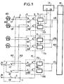
- the TU1, TUp, TUS terminal units are connected to the RCX connection by lines LR1 to LRp, LS.
- the lines are multiplex lines which can be common to several terminal units.
- Each subscriber terminal T1 to T8 of a terminal unit is connected to a subscriber line L1 to L8 through the two pairs of contacts re1 to re8 of a test reference relay (RE1 to RE8) of the terminal .
- One of the pairs of contacts has returns by a return line eL1 to eL8, the subscriber line to a line test robot REL connected to a line test bus BL.
- the other pair of contacts b makes it possible by a return line eJ to connect the terminal to a test robot for REJ trunks connected to a test bus for trunk BJ.
- TUS standby terminal unit made up of T1S to T8S standby terminals identical to subscriber terminals, on which all subscriber lines are switched over in the event of failure of any terminal which were served by the unit containing the faulty terminal.
- a return line, eL1 to eL8 is connected to the working contact of each of the test return relays for a terminal unit.
- a return line eJ is connected to the working contact of each of the test return relays of a terminal unit.
- the switching of a terminal unit is carried out by the rise of all the test reference relays RE1 to RE8 of this unit controlled by the control circuit CS.
- the identity of the faulty unit is communicated to the control circuit CS by the control members OC.
- the control circuit CS has a control link C1 to Cp to each of the terminal units TU1 to TUP. These control links must allow all the test relay relays to be mounted on the TU card regardless of the failure, including a power supply failure. They must therefore supply power to the eight relays.
- the backup terminal unit TUS is identical to the other terminal units TU1 to TUp and is also connected to the test bus of trunks BJ allowing the testing of its terminals.
- the line test robot REL would not be usable, which is not acceptable, such a robot serving for example 1000 lines. It is also not acceptable to deprive of service, during the whole duration of the tests which take place daily, the lines connected to the emergency terminal unit.
- the subscribers served by the same REL line test robot are divided into groups and the buses BL and BJ are connected to the terminals of a group of subscribers through an isolation circuit I.
- a. switching to a group allows the line tests of the other groups to be carried out.
- the tests in a group are short enough to allow the switching to be interrupted either continuously during the tests, or by successive tests relating each time to a terminal or a unit of terminals.
- Line circuits CL1 to CL8 are connected to buses B of the microprocessor (data bus, address bus and control bus).
- the matrix CX is also controlled by the microprocessor MP.
- the microprocessor MP dialogues with the OC control elements (fig. 1) using a signaling channel carried by one of the time channels of one of the lines multiplex.
- the microprocessor is connected to an input of the matrix CX through an access circuit CA.
- the access circuit CA is a known circuit which is commercially available and which allows the supervision of the exchange of messages on a signaling link according to the known procedure known as "HDLC". Such an exchange of messages between computers on a multiplex link is described in particular in document FR-A 2 451 141.
- FIG. 3 An example of a connection concerning the groups of GA1 to GAn terminal units served by the same set of ES test bodies is shown in FIG. 3.
- the ES set includes a REL line test robot and a REJ trunk test robot controlled by an MPE microprocessor.
- the ES assembly is connected to each group of GA terminal units through an isolation circuit I1 to In.
- the tests are controlled by the OC organs, connected to the MPE microprocessor by a signaling channel carried by MX multiplex lines connected to the RCX connection network, and similar to that which connects the microprocessors of the terminal units.
- the control circuit CS is preferably also controlled by a microprocessor connected to the control members by the same channel as the microprocessors of the terminal units of the same group.
- the control mode is thus the same for all microprocessors.
Landscapes
- Engineering & Computer Science (AREA)
- Signal Processing (AREA)
- Computer Networks & Wireless Communication (AREA)
- Monitoring And Testing Of Exchanges (AREA)
- Structure Of Telephone Exchanges (AREA)
Applications Claiming Priority (2)
| Application Number | Priority Date | Filing Date | Title |
|---|---|---|---|
| FR8106811 | 1981-04-03 | ||
| FR8106811A FR2503500A1 (fr) | 1981-04-03 | 1981-04-03 | Dispositif de secours de terminal d'abonne |
Publications (2)
| Publication Number | Publication Date |
|---|---|
| EP0062294A1 true EP0062294A1 (de) | 1982-10-13 |
| EP0062294B1 EP0062294B1 (de) | 1985-07-03 |
Family
ID=9257016
Family Applications (1)
| Application Number | Title | Priority Date | Filing Date |
|---|---|---|---|
| EP82102708A Expired EP0062294B1 (de) | 1981-04-03 | 1982-03-31 | Reserveeinrichtung für Teilnehmerleitungsanschlussgruppen |
Country Status (8)
| Country | Link |
|---|---|
| US (1) | US4451708A (de) |
| EP (1) | EP0062294B1 (de) |
| CA (1) | CA1176768A (de) |
| DE (1) | DE3264520D1 (de) |
| FR (1) | FR2503500A1 (de) |
| IE (1) | IE52838B1 (de) |
| IN (1) | IN158568B (de) |
| ZA (1) | ZA822216B (de) |
Cited By (4)
| Publication number | Priority date | Publication date | Assignee | Title |
|---|---|---|---|---|
| FR2555388A1 (fr) * | 1983-11-23 | 1985-05-24 | Cit Alcatel | Dispositif de secours d'un terminal d'abonne dans un concentrateur numerique |
| FR2557412A1 (fr) * | 1983-12-23 | 1985-06-28 | Cit Alcatel | Dispositif d'essais de joncteurs d'abonnes deux fils |
| FR2640101A1 (fr) * | 1988-12-06 | 1990-06-08 | Cit Alcatel | Dispositif de raccordement des lignes optiques a un central de telecommunication a large bande |
| EP0386369A3 (en) * | 1989-03-09 | 1990-12-27 | Gec Plessey Telecommunications Limited | Apparatus for testing and sparing linecard equipment in a telecommunications exchange |
Families Citing this family (15)
| Publication number | Priority date | Publication date | Assignee | Title |
|---|---|---|---|---|
| US4582960A (en) * | 1984-05-17 | 1986-04-15 | Porta Systems Corp. | Subscriber network interface device |
| GB2180430B (en) * | 1985-09-05 | 1989-08-23 | Motorola Inc | Subscriber line card arrangement |
| DE3633057C2 (de) * | 1986-09-29 | 1994-01-20 | Kommunikations Elektronik | Schaltungsanordnung zur Übertragung nachrichtentechnischer Signale |
| JPH0734550B2 (ja) * | 1987-02-02 | 1995-04-12 | 富士通株式会社 | 給電路切替回路 |
| US5050205A (en) * | 1990-10-25 | 1991-09-17 | Communication Devices, Inc. | Dial line monitor and control unit |
| JP3181963B2 (ja) * | 1992-02-17 | 2001-07-03 | 富士通株式会社 | 伝送端局装置 |
| US5321393A (en) * | 1992-04-10 | 1994-06-14 | Alcatel Network Systems, Inc. | Spare card connection and switching circuitry for high-speed telecommunications interfaces |
| US5321394A (en) * | 1992-04-10 | 1994-06-14 | Alcatel Network Systems, Inc. | Spare card connection circuitry for high-speed telecommunications transmitters/receivers and methods |
| US5425075A (en) * | 1993-08-12 | 1995-06-13 | Roln Company | Multipurpose analog telephony channel test facility method and apparatus |
| TW263636B (de) * | 1994-01-28 | 1995-11-21 | Siemens Ag | |
| US6259676B1 (en) | 1998-06-17 | 2001-07-10 | Nokia Telecommunications Oy | Upgrading of subscriber connection |
| FR2790628B1 (fr) * | 1999-03-02 | 2001-06-01 | Sextant Avionique | Reseau de distribution d'informations et procede de gestion de panne de ce reseau |
| US6556660B1 (en) * | 2001-04-25 | 2003-04-29 | At&T Corp. | Apparatus for providing redundant services path to customer premises equipment |
| US20060256931A1 (en) * | 2002-03-11 | 2006-11-16 | Udo Bendig | Contact bank measurement arrangement including a contact bank telecommunications module provided with contact bank or a measurement arrangement and telecommunications assembly including plural modules |
| DE20203911U1 (de) * | 2002-03-11 | 2003-07-17 | 3M Innovative Properties Co., St. Paul, Minn. | Kontaktfeld, Messanordnung mit einem Kontaktfeld und Anschluss-, Trenn- oder Zusatzmodul der Telekommunikationstechnik mit einem Kontaktfeld oder einer Messanordnung |
Family Cites Families (1)
| Publication number | Priority date | Publication date | Assignee | Title |
|---|---|---|---|---|
| JPS5938784B2 (ja) * | 1979-02-28 | 1984-09-19 | 富士通株式会社 | N+1予備方式 |
-
1981
- 1981-04-03 FR FR8106811A patent/FR2503500A1/fr active Pending
-
1982
- 1982-03-31 DE DE8282102708T patent/DE3264520D1/de not_active Expired
- 1982-03-31 EP EP82102708A patent/EP0062294B1/de not_active Expired
- 1982-03-31 ZA ZA822216A patent/ZA822216B/xx unknown
- 1982-04-02 CA CA000400383A patent/CA1176768A/fr not_active Expired
- 1982-04-02 IE IE791/82A patent/IE52838B1/en unknown
- 1982-04-05 US US06/365,851 patent/US4451708A/en not_active Expired - Lifetime
- 1982-07-07 IN IN514/DEL/82A patent/IN158568B/en unknown
Non-Patent Citations (2)
| Title |
|---|
| PATENTS ABSTRACTS OF JAPAN, volume 4, no. 170, 22 novembre 1980, page 652E35 & JP-A-55 115 786 (FUJITSU) 05-09-1980 * |
| SUPPLEMENT TO ELECTRICAL COMMUNICATION, volume 55, no. 2, 1980, LONDRES (GB) "Network terminals and control elements", pages 24/30 * |
Cited By (6)
| Publication number | Priority date | Publication date | Assignee | Title |
|---|---|---|---|---|
| FR2555388A1 (fr) * | 1983-11-23 | 1985-05-24 | Cit Alcatel | Dispositif de secours d'un terminal d'abonne dans un concentrateur numerique |
| EP0143431A1 (de) * | 1983-11-23 | 1985-06-05 | Alcatel Cit | Reserveeinrichtung für eine Teilnehmerleitungsgruppe in einem digitalen Konzentrator |
| FR2557412A1 (fr) * | 1983-12-23 | 1985-06-28 | Cit Alcatel | Dispositif d'essais de joncteurs d'abonnes deux fils |
| FR2640101A1 (fr) * | 1988-12-06 | 1990-06-08 | Cit Alcatel | Dispositif de raccordement des lignes optiques a un central de telecommunication a large bande |
| EP0372446A1 (de) * | 1988-12-06 | 1990-06-13 | Alcatel Cit | Vorrichtung zum Anschliessen von optischen Leitungen an einer Breibrandfernmeldeanlage |
| EP0386369A3 (en) * | 1989-03-09 | 1990-12-27 | Gec Plessey Telecommunications Limited | Apparatus for testing and sparing linecard equipment in a telecommunications exchange |
Also Published As
| Publication number | Publication date |
|---|---|
| IE52838B1 (en) | 1988-03-16 |
| DE3264520D1 (en) | 1985-08-08 |
| CA1176768A (fr) | 1984-10-23 |
| FR2503500A1 (fr) | 1982-10-08 |
| EP0062294B1 (de) | 1985-07-03 |
| ZA822216B (en) | 1983-02-23 |
| IE820791L (en) | 1982-10-03 |
| IN158568B (de) | 1986-12-13 |
| US4451708A (en) | 1984-05-29 |
Similar Documents
| Publication | Publication Date | Title |
|---|---|---|
| EP0062294B1 (de) | Reserveeinrichtung für Teilnehmerleitungsanschlussgruppen | |
| EP0143431B1 (de) | Reserveeinrichtung für eine Teilnehmerleitungsgruppe in einem digitalen Konzentrator | |
| US6449247B1 (en) | System and method for maintaining call services for remote users in the event of a communication failure | |
| EP1347591A3 (de) | Verfahren zum Lokalisieren eines Fehler in optischen Telekommunikationsnetzwerken | |
| CA1188003A (fr) | Dispositif de defense d'un autocommutateur a commande repartie | |
| US7382947B1 (en) | Remote monitoring of undersea cable systems | |
| US20040266268A1 (en) | Wideband filter installations and connections | |
| EP1648182B1 (de) | Verfahren zum Aufrüsten eines Zugriffsknotens einer Fernmeldevermittlungsstelle und aufgerüstete Fernmeldevermittlungsstelle | |
| AU661374B2 (en) | Metallic access in a fibre remote terminal | |
| BE898338A (fr) | Appareillage pour l'essai d'une seule ligne. | |
| US2901542A (en) | "wake up" or "morning call" system for automatically signaling private branch exchange extension stations | |
| KR100258240B1 (ko) | 넘버 7 망관리 분산 제어 방법 | |
| CN1265795A (zh) | 运行通信网络的方法和装置 | |
| NO934686L (no) | Svarstasjon til automatisk testing av terminaler tilsluttet et telekommunikasjonssystem | |
| EP0879528B1 (de) | Telekommunikationsnetzwerk | |
| JPH0530547A (ja) | 障害加入者カードの自動切替方式 | |
| WO2003030307A1 (en) | Improvements in broadband filter installations and connections | |
| FR2652976A1 (fr) | Repartiteur actif pour ispbx. | |
| JP3291429B2 (ja) | 遠隔加入者線多重装置 | |
| JPS60132496A (ja) | 加入者のユニツト間複式収容方式 | |
| KR19990031949A (ko) | 넘버 7 망관리 블록의 마스터/슬레이브 제어 방법 | |
| FR2481033A1 (fr) | Installation d'intercommunication electronique | |
| JPS6320945A (ja) | 加入者回路交換方式 | |
| JPS63211855A (ja) | 加入者回路インタ−フエ−ス装置 | |
| JPS6195655A (ja) | 自動交換機昼夜間切替方式 |
Legal Events
| Date | Code | Title | Description |
|---|---|---|---|
| PUAI | Public reference made under article 153(3) epc to a published international application that has entered the european phase |
Free format text: ORIGINAL CODE: 0009012 |
|
| AK | Designated contracting states |
Designated state(s): BE CH DE FR GB IT NL SE |
|
| 17P | Request for examination filed |
Effective date: 19830413 |
|
| ITF | It: translation for a ep patent filed | ||
| GRAA | (expected) grant |
Free format text: ORIGINAL CODE: 0009210 |
|
| AK | Designated contracting states |
Designated state(s): BE CH DE FR GB IT LI NL SE |
|
| REF | Corresponds to: |
Ref document number: 3264520 Country of ref document: DE Date of ref document: 19850808 |
|
| PLBE | No opposition filed within time limit |
Free format text: ORIGINAL CODE: 0009261 |
|
| STAA | Information on the status of an ep patent application or granted ep patent |
Free format text: STATUS: NO OPPOSITION FILED WITHIN TIME LIMIT |
|
| 26N | No opposition filed | ||
| PGFP | Annual fee paid to national office [announced via postgrant information from national office to epo] |
Ref country code: SE Payment date: 19900112 Year of fee payment: 9 |
|
| PGFP | Annual fee paid to national office [announced via postgrant information from national office to epo] |
Ref country code: CH Payment date: 19900115 Year of fee payment: 9 |
|
| PGFP | Annual fee paid to national office [announced via postgrant information from national office to epo] |
Ref country code: BE Payment date: 19900208 Year of fee payment: 9 |
|
| PGFP | Annual fee paid to national office [announced via postgrant information from national office to epo] |
Ref country code: DE Payment date: 19900222 Year of fee payment: 9 |
|
| PGFP | Annual fee paid to national office [announced via postgrant information from national office to epo] |
Ref country code: GB Payment date: 19900228 Year of fee payment: 9 |
|
| PGFP | Annual fee paid to national office [announced via postgrant information from national office to epo] |
Ref country code: NL Payment date: 19900331 Year of fee payment: 9 |
|
| PG25 | Lapsed in a contracting state [announced via postgrant information from national office to epo] |
Ref country code: CH Effective date: 19910331 Ref country code: GB Effective date: 19910331 Ref country code: LI Effective date: 19910331 Ref country code: BE Effective date: 19910331 |
|
| PG25 | Lapsed in a contracting state [announced via postgrant information from national office to epo] |
Ref country code: SE Effective date: 19910401 |
|
| BERE | Be: lapsed |
Owner name: CIE INDUSTRIELLE DES TELECOMMUNICATIONS CIT-ALCA Effective date: 19910331 |
|
| PG25 | Lapsed in a contracting state [announced via postgrant information from national office to epo] |
Ref country code: NL Effective date: 19911001 |
|
| NLV4 | Nl: lapsed or anulled due to non-payment of the annual fee | ||
| GBPC | Gb: european patent ceased through non-payment of renewal fee | ||
| REG | Reference to a national code |
Ref country code: CH Ref legal event code: PL |
|
| PG25 | Lapsed in a contracting state [announced via postgrant information from national office to epo] |
Ref country code: DE Effective date: 19920101 |
|
| ITTA | It: last paid annual fee | ||
| EUG | Se: european patent has lapsed |
Ref document number: 82102708.3 Effective date: 19911108 |
|
| PGFP | Annual fee paid to national office [announced via postgrant information from national office to epo] |
Ref country code: FR Payment date: 20010313 Year of fee payment: 20 |