EP0062294A1 - Dispositif de secours de terminal d'abonné - Google Patents
Dispositif de secours de terminal d'abonné Download PDFInfo
- Publication number
- EP0062294A1 EP0062294A1 EP82102708A EP82102708A EP0062294A1 EP 0062294 A1 EP0062294 A1 EP 0062294A1 EP 82102708 A EP82102708 A EP 82102708A EP 82102708 A EP82102708 A EP 82102708A EP 0062294 A1 EP0062294 A1 EP 0062294A1
- Authority
- EP
- European Patent Office
- Prior art keywords
- terminal
- test
- terminals
- terminal unit
- contacts
- Prior art date
- Legal status (The legal status is an assumption and is not a legal conclusion. Google has not performed a legal analysis and makes no representation as to the accuracy of the status listed.)
- Granted
Links
- 238000012360 testing method Methods 0.000 claims abstract description 70
- 238000002955 isolation Methods 0.000 claims description 14
- 230000015556 catabolic process Effects 0.000 claims description 2
- 230000008859 change Effects 0.000 claims description 2
- 210000000056 organ Anatomy 0.000 description 9
- 235000021183 entrée Nutrition 0.000 description 3
- 239000011159 matrix material Substances 0.000 description 3
- 230000011664 signaling Effects 0.000 description 3
- 230000003321 amplification Effects 0.000 description 2
- 238000006243 chemical reaction Methods 0.000 description 2
- 238000001514 detection method Methods 0.000 description 2
- 238000010586 diagram Methods 0.000 description 2
- 230000003993 interaction Effects 0.000 description 2
- 238000012423 maintenance Methods 0.000 description 2
- 230000004048 modification Effects 0.000 description 2
- 238000012986 modification Methods 0.000 description 2
- 238000003199 nucleic acid amplification method Methods 0.000 description 2
- 230000001629 suppression Effects 0.000 description 2
- 230000006978 adaptation Effects 0.000 description 1
- 230000004807 localization Effects 0.000 description 1
- 238000000034 method Methods 0.000 description 1
- 230000000135 prohibitive effect Effects 0.000 description 1
- 230000009467 reduction Effects 0.000 description 1
Images


Classifications
-
- H—ELECTRICITY
- H04—ELECTRIC COMMUNICATION TECHNIQUE
- H04Q—SELECTING
- H04Q11/00—Selecting arrangements for multiplex systems
- H04Q11/04—Selecting arrangements for multiplex systems for time-division multiplexing
-
- H—ELECTRICITY
- H04—ELECTRIC COMMUNICATION TECHNIQUE
- H04M—TELEPHONIC COMMUNICATION
- H04M3/00—Automatic or semi-automatic exchanges
- H04M3/08—Indicating faults in circuits or apparatus
- H04M3/12—Marking faulty circuits "busy"; Enabling equipment to disengage itself from faulty circuits ; Using redundant circuits; Response of a circuit, apparatus or system to an error
-
- H—ELECTRICITY
- H04—ELECTRIC COMMUNICATION TECHNIQUE
- H04M—TELEPHONIC COMMUNICATION
- H04M3/00—Automatic or semi-automatic exchanges
- H04M3/22—Arrangements for supervision, monitoring or testing
- H04M3/26—Arrangements for supervision, monitoring or testing with means for applying test signals or for measuring
- H04M3/28—Automatic routine testing ; Fault testing; Installation testing; Test methods, test equipment or test arrangements therefor
- H04M3/30—Automatic routine testing ; Fault testing; Installation testing; Test methods, test equipment or test arrangements therefor for subscriber's lines, for the local loop
Definitions
- the invention relates to a subscriber terminal backup device, in a system in which the subscriber terminals are connected to the subscriber lines by means of the contacts of the test reference relays.
- the invention is applicable in telecommunications, in particular in telephone exchanges.
- the subscriber terminal is the individual equipment of a telephone line. It includes the power supply, ringing, line adaptation means, supervision means, and test reference means.
- the terminal is connected to the line at the input distributor, and to the common members at an internal distributor which depends on the type of switch.
- the terminals are generally installed by 4 or 8 on printed circuit boards.
- a breakdown at the level of the card deprives a line or all the lines connected to this card of service, but taking into account the fact that the cost of all the terminals is high, these are not duplicated. They are tested daily, and the faults detected require intervention.
- the object of the device according to the invention is to solve this problem.
- the object of the invention is a subscriber terminal backup device in a system where the terminals are connected to the subscriber lines by means of pairs of forwarding relay contacts. during tests and in which the terminals are organized into terminal units, the standby device being able to be connected to a subscriber line whose terminal is broken down by means of pairs of test return contacts, characterized by the fact that it comprises a standby terminal unit fitted with test return relays comprising pairs of contacts and an isolation circuit connected to a line test bus, to a trunk test bus, and to the pairs of contacts of the terminal units and of the standby terminal unit, and making it possible to connect on the one hand the standby terminal unit either to the line test buses and trunks, or to the subscriber lines d 'a terminal unit presenting a fault, and on the other hand the terminal units to the test buses for lines and trunks.
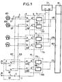
- the TU1, TUp, TUS terminal units are connected to the RCX connection by lines LR1 to LRp, LS.
- the lines are multiplex lines which can be common to several terminal units.
- Each subscriber terminal T1 to T8 of a terminal unit is connected to a subscriber line L1 to L8 through the two pairs of contacts re1 to re8 of a test reference relay (RE1 to RE8) of the terminal .
- One of the pairs of contacts has returns by a return line eL1 to eL8, the subscriber line to a line test robot REL connected to a line test bus BL.
- the other pair of contacts b makes it possible by a return line eJ to connect the terminal to a test robot for REJ trunks connected to a test bus for trunk BJ.
- TUS standby terminal unit made up of T1S to T8S standby terminals identical to subscriber terminals, on which all subscriber lines are switched over in the event of failure of any terminal which were served by the unit containing the faulty terminal.
- a return line, eL1 to eL8 is connected to the working contact of each of the test return relays for a terminal unit.
- a return line eJ is connected to the working contact of each of the test return relays of a terminal unit.
- the switching of a terminal unit is carried out by the rise of all the test reference relays RE1 to RE8 of this unit controlled by the control circuit CS.
- the identity of the faulty unit is communicated to the control circuit CS by the control members OC.
- the control circuit CS has a control link C1 to Cp to each of the terminal units TU1 to TUP. These control links must allow all the test relay relays to be mounted on the TU card regardless of the failure, including a power supply failure. They must therefore supply power to the eight relays.
- the backup terminal unit TUS is identical to the other terminal units TU1 to TUp and is also connected to the test bus of trunks BJ allowing the testing of its terminals.
- the line test robot REL would not be usable, which is not acceptable, such a robot serving for example 1000 lines. It is also not acceptable to deprive of service, during the whole duration of the tests which take place daily, the lines connected to the emergency terminal unit.
- the subscribers served by the same REL line test robot are divided into groups and the buses BL and BJ are connected to the terminals of a group of subscribers through an isolation circuit I.
- a. switching to a group allows the line tests of the other groups to be carried out.
- the tests in a group are short enough to allow the switching to be interrupted either continuously during the tests, or by successive tests relating each time to a terminal or a unit of terminals.
- Line circuits CL1 to CL8 are connected to buses B of the microprocessor (data bus, address bus and control bus).
- the matrix CX is also controlled by the microprocessor MP.
- the microprocessor MP dialogues with the OC control elements (fig. 1) using a signaling channel carried by one of the time channels of one of the lines multiplex.
- the microprocessor is connected to an input of the matrix CX through an access circuit CA.
- the access circuit CA is a known circuit which is commercially available and which allows the supervision of the exchange of messages on a signaling link according to the known procedure known as "HDLC". Such an exchange of messages between computers on a multiplex link is described in particular in document FR-A 2 451 141.
- FIG. 3 An example of a connection concerning the groups of GA1 to GAn terminal units served by the same set of ES test bodies is shown in FIG. 3.
- the ES set includes a REL line test robot and a REJ trunk test robot controlled by an MPE microprocessor.
- the ES assembly is connected to each group of GA terminal units through an isolation circuit I1 to In.
- the tests are controlled by the OC organs, connected to the MPE microprocessor by a signaling channel carried by MX multiplex lines connected to the RCX connection network, and similar to that which connects the microprocessors of the terminal units.
- the control circuit CS is preferably also controlled by a microprocessor connected to the control members by the same channel as the microprocessors of the terminal units of the same group.
- the control mode is thus the same for all microprocessors.
Landscapes
- Engineering & Computer Science (AREA)
- Signal Processing (AREA)
- Computer Networks & Wireless Communication (AREA)
- Monitoring And Testing Of Exchanges (AREA)
- Structure Of Telephone Exchanges (AREA)
Abstract
Description
- L'invention concerne un dispositif de secours de terminal d'abonné, dans un système où les terminaux d'abonnés sont reliés aux lignes des abonnés par l'intermédiaire des contacts des relais de renvoi aux essais de ces lignes.
- L'invention est applicable dans les télécommunications, en particulier dans les centraux téléphoniques. Le terminal d'abonné est l'équipement individuel d'une ligne téléphonique. Il comporte les moyens d'alimentation, de sonnerie, d'adaptation de la ligne, les moyens de supervision, et les moyens de renvoi aux essais. Le terminal est relié à la ligne au niveau du répartiteur d'entrée, et aux organes communs au niveau d'un répartiteur interne qui dépend du type de l'autocommutateur. Les terminaux sont en général implantés par 4 ou 8 sur des cartes de circuits imprimés.
- Une panne au niveau de la carte prive de service une ligne ou toutes les lignes raccordées à cette carte, mais compte tenu du fait que le coût de l'ensemble des terminaux est élevé, ceux-ci ne sont pas dupliqués. Ils sont essayés quotidiennement, et les pannes détectées nécessitent une intervention.
- Or, les progrès technologiques ont été tels que l'on exige une disponibilité pratiquement permanente des services et un nombre d'interventions par an très faible pour l'ensemble d'un central. Pour réduire le nombre d'interventions dues aux terminaux, il suffit d'introduire un terminal de secours pour plusieurs terminaux. Le problème à résoudre est alors d'une part la détection de panne et la commande de basculement d'un terminal sur un terminal de secours et d'autre part de disposer des relais et des points de sorties nécessaires sur les cartes de terminaux.
- Or, les cartes et leurs connecteurs sont chargés, et la diminution du nombre de terminaux par carte ou l'utilisation de moyens additionnels introduirait des coûts prohibitifs; le but du dispositif selon l'invention est de résoudre ce problème.
- L'objet de l'invention est un dispositif de secours de terminal d'abonné dans un système où les terminaux sont reliés aux lignes des abonnés par l'intermédiaire de paires de contacts de relais de renvoi aux essais et dans lequel les terminaux sont organisés en unités de terminaux, le dispositif de secours pouvant être connecté à une ligne d'abonné dont le terminal est en panne par l'intermédiaire des paires de contacts de renvoi aux essais, caractérisé par le fait qu'il comporte une unité de terminaux de secours munie de relais de renvoi aux essais comportant des paires de contacts et un circuit d'isolement relié à un bus d'essai de ligne, à un bus d'essai de joncteur, et aux paires de contacts des unités de terminaux et de l'unité de terminaux de secours, et permettant de relier d'une part l'unité de terminaux de secours soit aux bus d'essais de ligne et de joncteurs, soit aux lignes d'abonné d'une unité de terminaux présentant un défaut, et d'autre part les unités de terminaux aux bus d'essais de lignes et de joncteurs.
- L'invention va être précisée par la description qui va suivre d'un mode préféré de réalisation de l'invention, donné à titre d'exemple non limitatif, en référence au dessin annexé dans lequel :
- - La figure 1 représente un schéma d'un dispositif de secours de terminal d'abonnés selon l'invention.
- - La figure 2 est un schéma général d'un type d'unité de terminaux de la*figure 1.
- - La figure 3 est un exemple de disposition des organes dans un central temporel auquel est appliquée l'invention.
- Cette application de l'invention concerne un central téléphonique dans lequel les terminaux de lignes d'abonnés sont groupés en unités de terminaux TU ayant des parties en commun, par exemple les moyens de supervision et les liaisons de renvoi aux essais. Dans la figure 1 on n'a représenté que les parties du central utiles à la compréhension de l'invention :
- - Un ensemble d'organes de commande OC
- - Un réseau de connexion RCX
- - Des unités de terminaux TU1 à TUp, TUS
- - Un circuit de commande de mise en service du secours CS constitué par un dispositif de marquage connu
- - Un circuit d'isolement des liaisons de renvoi aux essais I
- Les unités de terminaux TU1, TUp, TUS sont reliées au réseau de connexion RCX par des lignes LR1 à LRp, LS. Dans le cas d'un central de type temporel, les lignes sont des lignes multiplex qui peuvent être communes à plusieurs unités de terminaux.
- Chaque terminal d'abonné T1 à T8 d'une unité de terminaux est relié à une ligne d'abonné L1 à L8 à travers les deux paires de contacts re1 à re8 d'un relais de renvoi aux essais (RE1 à RE8) du terminal. L'une des paires de contacts a renvoie par une ligne de renvoi eL1 à eL8, la ligne d'abonné vers un robot d'essai de lignes REL connecté à un bus d'essai de lignes BL. De même l'autre paire de contacts b permet par une ligne de renvoi eJ de relier le terminal à un robot d'essai de joncteurs REJ connecté à un bus d'essai de joncteur BJ.
- On dispose d'une unité de terminaux de secours TUS constituée de terminaux de secours T1S à T8S`identiques aux terminaux d'abonnés, sur laquelle on bascule, en cas de panne d'un terminal quelconque, l'ensemble des lignes d'abonnés qui étaient desservies par l'unité comportant le terminal en panne. Pour cela une ligne de renvoi, eL1 à eL8, est reliée au contact de travail de chacun des relais de renvoi aux essais d'une unité de terminaux. De même une ligne de renvoie eJ est reliée au contact de travail de chacun des relais de renvoi aux essais d'une unité de terminaux.
- Ces lignes de renvois eL1 à eL8, eJ sont multiplées sur toutes les unités de terminaux TU1 à TUp et sont connectées également à l'entrée des terminaux de secours de l'unité de terminaux de secours TUS.
- Le basculement d'une unité de terminaux est réalisé par la montée de tous les relais de renvoi aux essais RE1 à RE8 de cette unité commandés par le circuit de commande CS. L'identité de l'unité en panne est communiquée au circuit de commande CS par les organes de commande OC. Le circuit de commande CS possède une liaison de commande C1 à Cp vers chacune des unités de terminaux TU1 à TUP. Ces liaisons de commande doivent permettre de faire monter tous les relais de renvoi aux essais de la carte TU quelle que soit la panne, y compris une panne d'alimentation. Elles doivent donc fournir l'alimentation des huit relais.
- L'unité de terminaux de secours TUS est identique aux autres unités de terminaux TU1 à TUp et est également reliée au bus d'essai de joncteurs BJ permettant l'essai de ses terminaux.
- D'autre part si le bus d'essai de ligne BL était relié en permanence aux lignes de renvoi eL1 à eL8 en cas de basculement dû à une panne, le robot d'essai de lignes REL ne serait pas utilisable, ce qui n'est pas acceptable, un tel robot desservant par exemple 1000 lignes. Il n'est pas non plus acceptable de priver de service, pendant toute la durée des essais qui ont lieu quotidiennement, les lignes raccordées à l'unité de terminaux de secours.
- Selon l'invention les abonnés desservis par un même robot d'essai de lignes REL sont répartis en groupes et les bus BL et BJ sont reliés aux terminaux d'un groupe d'abonnés à travers un circuit d'isolement I. De cette manière un. basculement dans un groupe permet d'effectuer les essais de lignes des autres groupes. D'autre part les essais dans un groupe sont assez courts pour permettre d'interrompre le basculement soit d'une manière continue pendant les essais, soit par essais successifs portant à chaque fois sur un terminal ou une unité de terminaux.
- Le circuit d'isolement I est formé d'au moins un relais d'isolement comportant une paire de contacts travail ro sur le bus d'essai de joncteurs Bj, et une paire de contacts repos-travail r1 à r8 pour chacune des lignes de renvoi eL1 à eL8. Les contacts r1 à r8 sont câblés comme suit :
- - Les lames mobiles sont reliées aux lignes de renvoi eL1 à eL8
- - Les contacts repos sont reliés chacun à l'entrée d'un terminal de l'unité de terminaux de secours TUS.
- - Tous les contacts travail sont reliés au bus d'essai de lignes BL.
- La figure 2 représente une application particulière et non limitative de l'invention à des unités de terminaux commandées par un microprocesseur MP et reliées à un autocommutateur temporel. Cette unité comporte les éléments suivants :
- A - Des éléments individuels de chaque terminal :
- - des relais de renvoi aux essais RE1 à RE8 ;
- - des circuits de ligne CL1 à CL8 réalisant d'une part les fonctions classiques de joncteurs, par exemple à l'aide d'un circuit connu sous le nom de BORSHT, et d'autre part un circuit de conversion de type CODEC ;
- - des circuits "OU" 01 à 08 pour la commande des relais de renvoi d'essais : commande globale de secours par le circuit de commande CS (fig.1) (entrée Ci) ou commande d'essai individuel par le microprocesseur MP, par exemple à l'aide d'un décodeur de numéro de terminal DC. Naturellement les circuits "OU" 01 à 08 doivent permettre le passage du courant d'alimentation des relais, et comporter une amplification sur l'entrée venant du décodeur dans le cas où celui-ci est un circuit logique de faible puissance.
- B - Des éléments communs :
- - une matrice CX de connexion des circuits de ligne à 4 lignes multiplex MX1 à MX4 ;
- - Le microprocesseur MP de commande des terminaux.
- Les circuits de ligne CL1 à CL8 sont reliés aux bus B du microprocesseur (bus de données, bus d'adresse et bus de commande). La matrice CX est commandée également par le microprocesseur MP.
- Pour la commande des terminaux, des connexions et des essais, le microprocesseur MP dialogue avec les organes de commande OC (fig.1) à l'aide d'un canal sémaphore porté par l'une des voies temporelles de l'une des lignes multiplex. Pour cela le microprocesseur est relié à une entrée de la matrice CX à travers un circuit d'accès CA.
- Le circuit d'accès CA est un circuit connu que l'on trouve dans le commerce et qui permet la supervision des échanges de messages sur un canal sémaphore selon la procédure connue dite "HDLC". Un tel échange de messages entre calculateurs sur liaison multiplex est décrit notamment dans le document FR-A 2 451 141.
- Un exemple de liaison concernant les groupes d'unités de terminaux GA1 à GAn desservis par un même ensemble d'organes d'essais ES est représenté à la figure 3.
- L'ensemble ES comporte un robot d'essais de lignes REL et un robot d'essais de joncteurs REJ pilotés par un microprocesseur MPE. L'ensemble ES est relié à chaque groupe d'unités de terminaux GA à travers un circuit d'isolement I1 à In.
- Les essais sont commandés par les organes OC, reliés au microprocesseur MPE par un canal sémaphore porté par des lignes multiplex MX reliées au réseau de connexion RCX, et analogues à celui qui relie les microprocesseurs des unités de terminaux.
- Cet exemple n'est pas limitatif mais montre une application préférentielle de l'invention en ce qui concerne la localisation des circuits. permettant le secours :
- - Le circuit de commande CS et l'unité de secours de terminaux TUS affectés à un groupe d'unités de terminaux, GA1 à GAn, sont situés dans l'alvéole (ou l'un des alvéoles) des cartes des unités de terminaux TU1 à TUp
- - Les circuits d'isolement I1 à In sont situés dans l'ensemble d'organes d'essais ES et les relais d'isolement sont commandés par le microprocesseur MPE.
- Cette solution nécessite pour le secours des liaisons supplémentaires entre l'ensemble d'organes d'essais ES et les groupes d'unités -de terminaux GA, mais évite les intéractions entre logiciel de commutation et logiciel d'essais.
- Le circuit de commande CS est de préférence également piloté par un microprocesseur relié aux organes de commandes par le même canal que les microprocesseurs des unités de terminaux du même groupe. Le mode de commande est ainsi le même pour tous les microprocesseurs.
- Dans cette application le fonctionnement du secours et son intéraction sur les essais sont les suivants :
- - Décision de basculement prise par l'ensemble d'organes de commande OC : une unité de terminaux TU est détectée hors service suite à la détection d'une panne par les moyens de maintenance ou de localisation d'avaries, par le robot d'essai de joncteurs REJ, ou par les tests effectués sur les terminaux par le microprocesseur MP sur ordre de l'ensemble d'organes de commande OC.
- - Basculement par ordre de l'ensemble d'organes de commande OC au circuit de commande CS, lui indiquant le numéro de l'unité de terminaux mise hors service
- - Mise à jour des logiciels de l'ensemble d'organes de commande OC :
- Logiciel de traduction : changement des numéros des terminaux affectés aux 8 lignes d'abonnés concernées par le basculement.
- - Logiciel d'essais : modification des séquences du robot d'essais de lignes REL et introduction de commandes au circuit de commande CS pour coordonner les essais, au niveau du groupe d'unités de terminaux GA dans lequel a eu lieu le basculement avec les suppressions de basculement nécessaires à l'utilisation du bus d'essai de lignes BL.
De cette manière, pour procéder aux essais d'un groupe d'abonnés il faut commander le relais du circuit d'isolement I affecté à ce groupe.
Claims (6)
Applications Claiming Priority (2)
| Application Number | Priority Date | Filing Date | Title |
|---|---|---|---|
| FR8106811 | 1981-04-03 | ||
| FR8106811A FR2503500A1 (fr) | 1981-04-03 | 1981-04-03 | Dispositif de secours de terminal d'abonne |
Publications (2)
| Publication Number | Publication Date |
|---|---|
| EP0062294A1 true EP0062294A1 (fr) | 1982-10-13 |
| EP0062294B1 EP0062294B1 (fr) | 1985-07-03 |
Family
ID=9257016
Family Applications (1)
| Application Number | Title | Priority Date | Filing Date |
|---|---|---|---|
| EP82102708A Expired EP0062294B1 (fr) | 1981-04-03 | 1982-03-31 | Dispositif de secours de terminal d'abonné |
Country Status (8)
| Country | Link |
|---|---|
| US (1) | US4451708A (fr) |
| EP (1) | EP0062294B1 (fr) |
| CA (1) | CA1176768A (fr) |
| DE (1) | DE3264520D1 (fr) |
| FR (1) | FR2503500A1 (fr) |
| IE (1) | IE52838B1 (fr) |
| IN (1) | IN158568B (fr) |
| ZA (1) | ZA822216B (fr) |
Cited By (4)
| Publication number | Priority date | Publication date | Assignee | Title |
|---|---|---|---|---|
| FR2555388A1 (fr) * | 1983-11-23 | 1985-05-24 | Cit Alcatel | Dispositif de secours d'un terminal d'abonne dans un concentrateur numerique |
| FR2557412A1 (fr) * | 1983-12-23 | 1985-06-28 | Cit Alcatel | Dispositif d'essais de joncteurs d'abonnes deux fils |
| FR2640101A1 (fr) * | 1988-12-06 | 1990-06-08 | Cit Alcatel | Dispositif de raccordement des lignes optiques a un central de telecommunication a large bande |
| EP0386369A3 (en) * | 1989-03-09 | 1990-12-27 | Gec Plessey Telecommunications Limited | Apparatus for testing and sparing linecard equipment in a telecommunications exchange |
Families Citing this family (15)
| Publication number | Priority date | Publication date | Assignee | Title |
|---|---|---|---|---|
| US4582960A (en) * | 1984-05-17 | 1986-04-15 | Porta Systems Corp. | Subscriber network interface device |
| GB2180430B (en) * | 1985-09-05 | 1989-08-23 | Motorola Inc | Subscriber line card arrangement |
| DE3633057C2 (de) * | 1986-09-29 | 1994-01-20 | Kommunikations Elektronik | Schaltungsanordnung zur Übertragung nachrichtentechnischer Signale |
| JPH0734550B2 (ja) * | 1987-02-02 | 1995-04-12 | 富士通株式会社 | 給電路切替回路 |
| US5050205A (en) * | 1990-10-25 | 1991-09-17 | Communication Devices, Inc. | Dial line monitor and control unit |
| JP3181963B2 (ja) * | 1992-02-17 | 2001-07-03 | 富士通株式会社 | 伝送端局装置 |
| US5321394A (en) * | 1992-04-10 | 1994-06-14 | Alcatel Network Systems, Inc. | Spare card connection circuitry for high-speed telecommunications transmitters/receivers and methods |
| US5321393A (en) * | 1992-04-10 | 1994-06-14 | Alcatel Network Systems, Inc. | Spare card connection and switching circuitry for high-speed telecommunications interfaces |
| US5425075A (en) * | 1993-08-12 | 1995-06-13 | Roln Company | Multipurpose analog telephony channel test facility method and apparatus |
| TW263636B (fr) * | 1994-01-28 | 1995-11-21 | Siemens Ag | |
| US6259676B1 (en) | 1998-06-17 | 2001-07-10 | Nokia Telecommunications Oy | Upgrading of subscriber connection |
| FR2790628B1 (fr) * | 1999-03-02 | 2001-06-01 | Sextant Avionique | Reseau de distribution d'informations et procede de gestion de panne de ce reseau |
| US6556660B1 (en) * | 2001-04-25 | 2003-04-29 | At&T Corp. | Apparatus for providing redundant services path to customer premises equipment |
| DE20203911U1 (de) * | 2002-03-11 | 2003-07-17 | 3M Innovative Properties Co., St. Paul, Minn. | Kontaktfeld, Messanordnung mit einem Kontaktfeld und Anschluss-, Trenn- oder Zusatzmodul der Telekommunikationstechnik mit einem Kontaktfeld oder einer Messanordnung |
| US20060256931A1 (en) * | 2002-03-11 | 2006-11-16 | Udo Bendig | Contact bank measurement arrangement including a contact bank telecommunications module provided with contact bank or a measurement arrangement and telecommunications assembly including plural modules |
Family Cites Families (1)
| Publication number | Priority date | Publication date | Assignee | Title |
|---|---|---|---|---|
| JPS5938784B2 (ja) * | 1979-02-28 | 1984-09-19 | 富士通株式会社 | N+1予備方式 |
-
1981
- 1981-04-03 FR FR8106811A patent/FR2503500A1/fr active Pending
-
1982
- 1982-03-31 EP EP82102708A patent/EP0062294B1/fr not_active Expired
- 1982-03-31 ZA ZA822216A patent/ZA822216B/xx unknown
- 1982-03-31 DE DE8282102708T patent/DE3264520D1/de not_active Expired
- 1982-04-02 CA CA000400383A patent/CA1176768A/fr not_active Expired
- 1982-04-02 IE IE791/82A patent/IE52838B1/en unknown
- 1982-04-05 US US06/365,851 patent/US4451708A/en not_active Expired - Lifetime
- 1982-07-07 IN IN514/DEL/82A patent/IN158568B/en unknown
Non-Patent Citations (2)
| Title |
|---|
| PATENTS ABSTRACTS OF JAPAN, volume 4, no. 170, 22 novembre 1980, page 652E35 & JP-A-55 115 786 (FUJITSU) 05-09-1980 * |
| SUPPLEMENT TO ELECTRICAL COMMUNICATION, volume 55, no. 2, 1980, LONDRES (GB) "Network terminals and control elements", pages 24/30 * |
Cited By (6)
| Publication number | Priority date | Publication date | Assignee | Title |
|---|---|---|---|---|
| FR2555388A1 (fr) * | 1983-11-23 | 1985-05-24 | Cit Alcatel | Dispositif de secours d'un terminal d'abonne dans un concentrateur numerique |
| EP0143431A1 (fr) * | 1983-11-23 | 1985-06-05 | Alcatel Cit | Dispositif de secours d'un terminal d'abonné dans un concentrateur numérique |
| FR2557412A1 (fr) * | 1983-12-23 | 1985-06-28 | Cit Alcatel | Dispositif d'essais de joncteurs d'abonnes deux fils |
| FR2640101A1 (fr) * | 1988-12-06 | 1990-06-08 | Cit Alcatel | Dispositif de raccordement des lignes optiques a un central de telecommunication a large bande |
| EP0372446A1 (fr) * | 1988-12-06 | 1990-06-13 | Alcatel Cit | Dispositif de raccordement des lignes optiques à un central de télécommunication à large bande |
| EP0386369A3 (en) * | 1989-03-09 | 1990-12-27 | Gec Plessey Telecommunications Limited | Apparatus for testing and sparing linecard equipment in a telecommunications exchange |
Also Published As
| Publication number | Publication date |
|---|---|
| EP0062294B1 (fr) | 1985-07-03 |
| FR2503500A1 (fr) | 1982-10-08 |
| IE820791L (en) | 1982-10-03 |
| IN158568B (fr) | 1986-12-13 |
| US4451708A (en) | 1984-05-29 |
| DE3264520D1 (en) | 1985-08-08 |
| ZA822216B (en) | 1983-02-23 |
| CA1176768A (fr) | 1984-10-23 |
| IE52838B1 (en) | 1988-03-16 |
Similar Documents
| Publication | Publication Date | Title |
|---|---|---|
| EP0062294B1 (fr) | Dispositif de secours de terminal d'abonné | |
| EP0143431B1 (fr) | Dispositif de secours d'un terminal d'abonné dans un concentrateur numérique | |
| US5465294A (en) | System and method for recovering from a telecommunications disaster | |
| US6449247B1 (en) | System and method for maintaining call services for remote users in the event of a communication failure | |
| US3867588A (en) | Quick disconnect for telecommunication lines | |
| US7805032B1 (en) | Remote monitoring of undersea cable systems | |
| EP1347591A3 (fr) | Procédé pour localiser des pannes dans des réseaux de télécommunication optiques | |
| CA1188003A (fr) | Dispositif de defense d'un autocommutateur a commande repartie | |
| GB2229063A (en) | Testing and sparing telecommunications exchange linecards | |
| US20040005049A1 (en) | Apparatus and method for providing switching at a telephone cross-connect | |
| EP1648182B1 (fr) | Procédé pour la mise à jour d'équipement d'accès dans une centrale de télécommunication et une centrale de télécommunication améliorée | |
| AU661374B2 (en) | Metallic access in a fibre remote terminal | |
| BE898338A (fr) | Appareillage pour l'essai d'une seule ligne. | |
| NO934686D0 (no) | Svarstasjon til automatisk testing av terminaler tilsluttet et telekommunikasjonssystem | |
| KR100258240B1 (ko) | 넘버 7 망관리 분산 제어 방법 | |
| EP0879528B1 (fr) | Reseaux de telecommunications | |
| JPH0530547A (ja) | 障害加入者カードの自動切替方式 | |
| EP1433226A1 (fr) | Ameliorations apportees aux installations et aux connexions de filtres a large bande | |
| FR2652976A1 (fr) | Repartiteur actif pour ispbx. | |
| JP3291429B2 (ja) | 遠隔加入者線多重装置 | |
| JPS60132496A (ja) | 加入者のユニツト間複式収容方式 | |
| KR19990031949A (ko) | 넘버 7 망관리 블록의 마스터/슬레이브 제어 방법 | |
| JPS63211855A (ja) | 加入者回路インタ−フエ−ス装置 | |
| JPS61216557A (ja) | 端末装置試験方式 | |
| JPS6195655A (ja) | 自動交換機昼夜間切替方式 |
Legal Events
| Date | Code | Title | Description |
|---|---|---|---|
| PUAI | Public reference made under article 153(3) epc to a published international application that has entered the european phase |
Free format text: ORIGINAL CODE: 0009012 |
|
| AK | Designated contracting states |
Designated state(s): BE CH DE FR GB IT NL SE |
|
| 17P | Request for examination filed |
Effective date: 19830413 |
|
| ITF | It: translation for a ep patent filed | ||
| GRAA | (expected) grant |
Free format text: ORIGINAL CODE: 0009210 |
|
| AK | Designated contracting states |
Designated state(s): BE CH DE FR GB IT LI NL SE |
|
| REF | Corresponds to: |
Ref document number: 3264520 Country of ref document: DE Date of ref document: 19850808 |
|
| PLBE | No opposition filed within time limit |
Free format text: ORIGINAL CODE: 0009261 |
|
| STAA | Information on the status of an ep patent application or granted ep patent |
Free format text: STATUS: NO OPPOSITION FILED WITHIN TIME LIMIT |
|
| 26N | No opposition filed | ||
| PGFP | Annual fee paid to national office [announced via postgrant information from national office to epo] |
Ref country code: SE Payment date: 19900112 Year of fee payment: 9 |
|
| PGFP | Annual fee paid to national office [announced via postgrant information from national office to epo] |
Ref country code: CH Payment date: 19900115 Year of fee payment: 9 |
|
| PGFP | Annual fee paid to national office [announced via postgrant information from national office to epo] |
Ref country code: BE Payment date: 19900208 Year of fee payment: 9 |
|
| PGFP | Annual fee paid to national office [announced via postgrant information from national office to epo] |
Ref country code: DE Payment date: 19900222 Year of fee payment: 9 |
|
| PGFP | Annual fee paid to national office [announced via postgrant information from national office to epo] |
Ref country code: GB Payment date: 19900228 Year of fee payment: 9 |
|
| PGFP | Annual fee paid to national office [announced via postgrant information from national office to epo] |
Ref country code: NL Payment date: 19900331 Year of fee payment: 9 |
|
| PG25 | Lapsed in a contracting state [announced via postgrant information from national office to epo] |
Ref country code: CH Effective date: 19910331 Ref country code: GB Effective date: 19910331 Ref country code: LI Effective date: 19910331 Ref country code: BE Effective date: 19910331 |
|
| PG25 | Lapsed in a contracting state [announced via postgrant information from national office to epo] |
Ref country code: SE Effective date: 19910401 |
|
| BERE | Be: lapsed |
Owner name: CIE INDUSTRIELLE DES TELECOMMUNICATIONS CIT-ALCA Effective date: 19910331 |
|
| PG25 | Lapsed in a contracting state [announced via postgrant information from national office to epo] |
Ref country code: NL Effective date: 19911001 |
|
| NLV4 | Nl: lapsed or anulled due to non-payment of the annual fee | ||
| GBPC | Gb: european patent ceased through non-payment of renewal fee | ||
| REG | Reference to a national code |
Ref country code: CH Ref legal event code: PL |
|
| PG25 | Lapsed in a contracting state [announced via postgrant information from national office to epo] |
Ref country code: DE Effective date: 19920101 |
|
| ITTA | It: last paid annual fee | ||
| EUG | Se: european patent has lapsed |
Ref document number: 82102708.3 Effective date: 19911108 |
|
| PGFP | Annual fee paid to national office [announced via postgrant information from national office to epo] |
Ref country code: FR Payment date: 20010313 Year of fee payment: 20 |