EP0062297B1 - Installation de chauffage et de ventilation - Google Patents
Installation de chauffage et de ventilation Download PDFInfo
- Publication number
- EP0062297B1 EP0062297B1 EP82102724A EP82102724A EP0062297B1 EP 0062297 B1 EP0062297 B1 EP 0062297B1 EP 82102724 A EP82102724 A EP 82102724A EP 82102724 A EP82102724 A EP 82102724A EP 0062297 B1 EP0062297 B1 EP 0062297B1
- Authority
- EP
- European Patent Office
- Prior art keywords
- air
- heating
- temperature
- room
- rooms
- Prior art date
- Legal status (The legal status is an assumption and is not a legal conclusion. Google has not performed a legal analysis and makes no representation as to the accuracy of the status listed.)
- Expired
Links
- 238000010438 heat treatment Methods 0.000 title claims abstract description 137
- 238000009423 ventilation Methods 0.000 title claims description 27
- 238000009434 installation Methods 0.000 title claims 10
- 230000001105 regulatory effect Effects 0.000 description 8
- 238000001816 cooling Methods 0.000 description 3
- 230000006978 adaptation Effects 0.000 description 2
- 230000001276 controlling effect Effects 0.000 description 2
- 230000001419 dependent effect Effects 0.000 description 2
- 230000000694 effects Effects 0.000 description 2
- 230000007774 longterm Effects 0.000 description 2
- 230000005855 radiation Effects 0.000 description 2
- XLYOFNOQVPJJNP-UHFFFAOYSA-N water Substances O XLYOFNOQVPJJNP-UHFFFAOYSA-N 0.000 description 2
- 238000010521 absorption reaction Methods 0.000 description 1
- 230000003213 activating effect Effects 0.000 description 1
- 238000004378 air conditioning Methods 0.000 description 1
- 230000005540 biological transmission Effects 0.000 description 1
- 238000001514 detection method Methods 0.000 description 1
- 239000002184 metal Substances 0.000 description 1
- 230000003134 recirculating effect Effects 0.000 description 1
- 238000011084 recovery Methods 0.000 description 1
- 230000000284 resting effect Effects 0.000 description 1
- 230000035943 smell Effects 0.000 description 1
- 238000002604 ultrasonography Methods 0.000 description 1
- 230000036642 wellbeing Effects 0.000 description 1
Images

Classifications
-
- F—MECHANICAL ENGINEERING; LIGHTING; HEATING; WEAPONS; BLASTING
- F24—HEATING; RANGES; VENTILATING
- F24D—DOMESTIC- OR SPACE-HEATING SYSTEMS, e.g. CENTRAL HEATING SYSTEMS; DOMESTIC HOT-WATER SUPPLY SYSTEMS; ELEMENTS OR COMPONENTS THEREFOR
- F24D19/00—Details
- F24D19/10—Arrangement or mounting of control or safety devices
- F24D19/1084—Arrangement or mounting of control or safety devices for air heating systems
-
- F—MECHANICAL ENGINEERING; LIGHTING; HEATING; WEAPONS; BLASTING
- F24—HEATING; RANGES; VENTILATING
- F24D—DOMESTIC- OR SPACE-HEATING SYSTEMS, e.g. CENTRAL HEATING SYSTEMS; DOMESTIC HOT-WATER SUPPLY SYSTEMS; ELEMENTS OR COMPONENTS THEREFOR
- F24D5/00—Hot-air central heating systems; Exhaust gas central heating systems
- F24D5/02—Hot-air central heating systems; Exhaust gas central heating systems operating with discharge of hot air into the space or area to be heated
-
- F—MECHANICAL ENGINEERING; LIGHTING; HEATING; WEAPONS; BLASTING
- F24—HEATING; RANGES; VENTILATING
- F24D—DOMESTIC- OR SPACE-HEATING SYSTEMS, e.g. CENTRAL HEATING SYSTEMS; DOMESTIC HOT-WATER SUPPLY SYSTEMS; ELEMENTS OR COMPONENTS THEREFOR
- F24D9/00—Central heating systems employing combinations of heat transfer fluids covered by two or more of groups F24D1/00 - F24D7/00
Definitions
- the invention relates to a heating and ventilation system for a building unit with several rooms, with a relatively sluggish basic heating system, in particular a wall or floor heating, and an additional heating system in the form of a quickly controllable air heating, which is fed with a constant amount of fresh air from the outside and for all rooms provide fresh air with a uniform temperature.
- radiators in the form of radiators and in particular also the surface heating, such as floor or wall heating, have a high thermal inertia. This means that they react only slowly to temperature fluctuations in the room in question, so that the actual value of the temperature from the z. B. setpoint set on a thermostat can temporarily deviate significantly.
- the room users are ventilated by opening windows. Large temperature jumps and large heat losses occur because heat recovery from the air is not possible and because the radiators emit large amounts of heat, especially when the window is open.
- Warm air heating in which heated air is conveyed into the room, reacts relatively quickly.
- Warm air heaters have the disadvantage, however, that air has only a small heat absorption capacity, so that if only warm air is heated in a room, considerable amounts of air have to be supplied.
- recirculating air is used in these systems. that is, the air is sent back from the rooms to the ventilation unit and warmed up there again.
- Annoying smells are transmitted to all heated rooms.
- fresh air added is distributed evenly at all times to all rooms, including unused rooms, so that used rooms receive too little fresh air.
- a temporary lowering of the room temperature is associated with a reduction in comfort because there is no compensation for radiation from windows and cold walls due to heat radiation from warm heating surfaces.
- the invention is based on a combined heating system known from DE-A-2 041 961, which consist of an inert heating system which covers part of the heat load, and in which the remaining heat requirement and the fresh air requirement are covered by air heating.
- the air is drawn in as fresh air from the outside air, warmed depending on the outside temperature and introduced into the room.
- the room air is then discharged outdoors.
- the adaptation to the actual instantaneous heat requirement of the room is slow because the room temperature control is carried out by the slow basic heating system. A lot of energy is lost due to the permanent ventilation of the unused rooms.
- FR-A-2 321 666 describes a combined ventilation system in which a basic heating in the form of an underfloor heating and also an additional heating in the form of an air heating are provided.
- the air is drawn in from the room, passed through the heated floor and blown back into the room.
- the combined heating means that part of the thermal energy is supplied to the room as radiant heat and another part of the thermal energy as convex heat. Ventilation is not provided here. Adaptation to temperature fluctuations in the room is also relatively slow.
- US-A-4060123 describes a heating or cooling unit for hotel rooms and the like. The like. By activating a key or a code card, a presence detector is activated, which switches the heating or cooling device to a higher output. In this way it is achieved that the device works with low energy when no one is present in the room and develops its full performance only when the key or the code card has been actuated. A thermally inert basic heating system is not provided here.
- a central air heating system for several rooms is known from DE-A-1 908 500, in which the air is heated uniformly for all rooms.
- the inlet duct to each of the rooms has an air flap controlled by a thermostat.
- the positions of all air flaps are sensed and used to control a motor that controls the supply of heating energy to the heating source that heats the fresh air supplied.
- a basic heating system is not available here either.
- the invention has for its object to provide a heating and ventilation system in which the heating and ventilation of the individual rooms takes place to the extent that these rooms are used in order to avoid unnecessary heating energy expenditure. Temporary lowering and raising of the room temperature should take place quickly, as with air heating, but without the disadvantages of air heating such as odor transmission and poor outside air distribution being transferred to unused rooms.
- each room has at least one air volume control element for controlling the supply of heated fresh air, which is controlled by a thermostat, which can be actuated via a switch that can be actuated when entering the room or an automatically responding detector can be switched between a low first set temperature value and a higher second set temperature value, and the temperature of the fresh air is dependent speed is controlled by the total air requirement of several rooms.
- the invention is based on the idea that rooms which are not currently being used, that is to say rooms in which no one is present and which therefore have to be kept at a relatively low temperature level, do not require any additional ventilation. For these rooms, natural ventilation through leaks in windows and doors, etc. is sufficient. These rooms are therefore only heated to a minimum temperature by the basic heating. Those rooms in which a higher temperature level is to be reached, that is to say those rooms that are used, are additionally supplied with heated fresh air, whereby on the one hand these rooms are additionally heated and on the other hand are supplied with fresh air. For the entire building unit, the temperature of the warm air to be supplied to the rooms is constant and the temperature is controlled by regulating the amount of warm air to be supplied to the individual room. To the extent that additional heat is supplied by warm air, ventilation takes place at the same time. If the room is no longer used, the system switches to a lower temperature setpoint and the fresh air supply is saved there.
- the invention is based on the idea that when using a room in an apartment, a family home or in an office unit normally a certain number of people, for example, in this room. B. three or four people is not exceeded. If there is a larger number of people in the room on special occasions, the large number of people and body heat create excess heat in well-insulated rooms. Then ventilation can be carried out in the usual way by opening doors or windows. These rarely occurring cases should be disregarded when explaining the inventive concept. For such cases, a separate operating program can be provided if necessary, in which the air system supplies a large amount of fresh air at a low temperature.
- the supply air flow (warm air flow) is only directed into those rooms that are used. If this is only the case for a single room, the entire warm air flow of the central air conditioning device is available for this single room, while all other rooms are heated to the set minimum temperature solely by the basic heating system.
- the supply air volume is regulated thermostatically so that the supply air flow is steadily reduced after the effective room temperature setpoint is reached.
- the presence detectors required for this are known from intrusion detection systems. For example, it can be an infrared sensor that detects the presence or change of warm bodies in the room, or it can also be an ultrasound device that works on the Doppler principle. Other types of presence detectors are also possible. So z. B. actuating a selector switch or closing a door contact to control the higher temperature setpoint.
- the heating and ventilation system according to the invention has the advantage that the rooms can be kept at the low basic temperature when no one is present and can only be brought to the higher target temperature by the warm air heating when a person enters the room.
- This temperature increase can be achieved in a very short time due to the quick effect of the hot air heating, so that a reduced temperature can be accepted without loss of comfort during the period of non-use.
- Experience shows that if rooms are initially at a low temperature when entering, this is not perceived as unpleasant. Only when the person entering is in the room for a longer period of time, does the temperature feel too low as uncomfortably cool. This is avoided by the invention due to the quick adaptability of the additional hot air heating.
- the basic heating system can be designed very simply. It is sufficient for. B. a simple floor heating, the temperature of z. B. can be controlled depending on the outside temperature. Hollow floor heating in which air circulates in the cavity of a raised floor is particularly suitable.
- the heat output of the basic heating system can be changed depending on the heat output required by the additional heating system. If, for example, the warm air heating has to deliver a large amount of air at a high temperature over a long period of time, the controller can raise the temperature of the basic heating system. On the other hand, the temperature of the basic heating system can be reduced if the amount of heat and air required for warm air heating falls below a minimum value over a long period of time. In any case, the regulation of the additional heating system (warm air heating) takes priority over the regulation of the basic heating system.
- Both the basic heating and the additional heating require a heat source.
- the two heating systems are normally separated from one another, the basic heating system having a closed circuit in which a heat transfer medium circulates.
- the basic heating system is also an air heater, that the returning air flow of the basic heating system and fresh air are supplied to a single heating source and that for each room the amount of air supplied to the air volume control member is branched off from the amount of air supplied to the basic heater of this room.
- This variant is particularly suitable for cases in which the basic heating system is a hollow floor heating.
- the warm air heating delivers air with a constant temperature and in a constant total amount, the regulation for each room being carried out exclusively by changing the air volume for this room.
- sensors are provided according to an advantageous development of the invention for determining the total instantaneous requirement of all rooms for warm air. The sensors cause the warm air temperature to increase if the air outlet openings are opened more than the specified amount. This means that primarily the temperature control of a room is carried out by regulating the volume of the warm air supplied and that secondly the warm air temperature can also be changed within limits.
- the temperature of the basic heating system is only changed if necessary.
- the sensors for determining the total current demand of all rooms can be limit switches, for example, which respond to the open position of the air outlet openings. For example, if more than a predetermined number of air outlet openings are in the fully open state, the warm air temperature can be increased.
- the sensors can also respond to the pressure in the warm air distribution system. This pressure is lower the further the air outlet openings are open. If the pressure drops below a certain minimum value, it is concluded from this that the heating power of the hot air is insufficient, so that the hot air temperature must be increased.
- the air volume can be temporarily increased above the normal outdoor air volume.
- the thermostats are controlled by door and / or window contacts. When the door or window is open, the ventilation and additional heating are completely interrupted, so that unnecessary warm air losses are avoided.
- Fig. 1 a floor plan of a single-family house is shown schematically, which is completely enclosed by the outer walls 10.
- the outer walls 10 have windows and doors 11.
- the entire floor of the building is a raised floor with a raised floor cavity, the upper floor forming the floor resting on numerous supports (not shown) on the sub-floor, which consists for example of a concrete ceiling.
- Warm air is passed through the raised floor cavity so that the top floor assumes a surface temperature in the range from 22 ° C. to 28 ° C.
- the air system of the raised floor cavity is a closed air recirculation system, i.e. H. the air contained in it circulates constantly between a heater 12 and the raised floor cavity, so that this air does not get into the rooms. So that the air is evenly distributed in the raised floor cavity over the entire cross-sectional area of the building, the raised floor cavity has air guiding elements so that the large mass of the circulating warm air is guided along certain paths.
- This floor heating forms the basic heating system in this example.
- the heater 12 also effects the additional heating.
- the heater 12 is supplied with outside air.
- This outside air is heated and reaches the warm air duct 15, which is connected to an annular duct 16, which runs along the outer wall 10 and passes through all the rooms to be heated.
- the annular channel 16 is constructed, for example, as a sheet metal channel. It has air outlet openings 18 in the individual rooms R1, R2, R3 and R4 to be heated, the outlet cross section of which is adjustable.
- the size of the outlet cross section of each air outlet voltage 18 is regulated by a room thermostat 17.
- An outside temperature sensor 19 adjusts the air temperature of the underfloor heating depending on the outside temperature.
- Fig. 1 an additional variant is shown in the room R3, which can also be used in the other rooms.
- openings 26 are provided between the annular channel 16 and the hollow floor. Warm air enters the hollow floor through these openings 26 and heats it.
- an opening 27 is provided in the floor in the room R3, through which room air is sucked into the hollow floor. This air heats up on its way to the heater 12 in the hollow floor, whereby the amount of air supplied to the heater 12 increases and the temperature of this amount of air is increased by preheating.
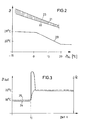
- the control characteristic 20 of the floor temperature as a function of the temperature 1 & AL of the outside air.
- the temperature of the underfloor heating is set so that the floor temperature is 22 ° C. If the outside temperature drops to 0 ° C, the floor temperature is raised to 26 ° C. With further cooling, the floor temperature remains at 26 ° C.
- a room temperature of 18 ° C This is the basic temperature to which the rooms are preheated. Such a temperature is generally not sufficient for human well-being. Therefore, the additional heating of the rooms can be done with the additional heating with heated fresh air.
- the control characteristic 21 of the auxiliary heater is also shown in FIG. 2.
- Line 22 indicates the temperature to which the fresh air is heated by the heating device 12 as a function of the outside temperature. It is therefore the temperature of the warm air flowing in the annular duct 16.
- the temperature of this warm air is initially independent of the temperatures in the individual rooms.
- different amounts of warm air are introduced into the individual rooms R1 to R4. For example, if there are only people in room R3, the air outlet openings 18 of rooms R1, R2 and R4 are closed, so that the temperature of 18 ° C. is established in these rooms in the long term, and only in room R3 is the temperature from the thermostat 17 regulated to the desired value. Practically the entire warm air energy of the additional heating or the ring duct 16 is available for the room R3.
- the exhaust system is not shown in FIG. 2. Because heated fresh air is supplied to rooms R1 to R4, used air is forced out of these rooms.
- the exhaust air is discharged through ducts and can be used in a heat exchanger to preheat the fresh air drawn in through duct 14.
- the solid line 24 indicates the heating power Q that is supplied to a room.
- the dashed line 25 indicates the room temperature.
- the room has a temperature of 18 ° C, which is only applied by the underfloor heating.
- a command to increase the room temperature to 20 ° C. is given by a timer or by a presence detector at time t 1 .
- the air outlet opening 18 is fully opened, so that a large amount of warm air flows into the room within a short time. Due to the supplied (fresh) warm air, there is also a strong ventilation of the room.
- the heat output (curve 24) rises to a maximum value within a very short time, until the thermostat 17 partially closes the air outlet opening 18 again.
- the thermal output is set to a value that corresponds to the room temperature of 20 ° C., which is predetermined by the thermostat 17.
- the target room temperature is reached within a very short time.
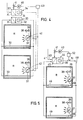
- the basic heating system contains a heater 30, which consists of a heat exchanger 31 and a pump or a fan 32.
- the heat exchanger 31 is supplied with heat via a boiler or a hot water pipe and heats the heat transfer medium which circulates in the closed circuit of the basic heating system.
- Each of the rooms R connected to the basic heating system contains at least one basic heating element 33, which in the case of air heating is, for. B. can be the cavity of a raised floor and in the case of hot water heating a radiator.
- the inlets of the basic heating element 33 are connected to the outlet of the heating device 32 and the outlets of the basic heating element 33 are connected to the inlet of the heating device 32 via corresponding channels or pipes.
- a separate heating device 34 with a heat exchanger 35 and a blower 36 is provided for the additional heating system.
- Outside air is drawn in through the heat exchanger 35 via line 53. After heating by the heat exchanger 35, this outside air is supplied by the blower 36 to the air quantity control members 37 which are present in the individual rooms.
- the air volume control members 37 are each an air flap, the opening position of which can be regulated by a thermostat 38 installed in the room R, so that the amount of the heated fresh air entering the room via the thermostats 38 by adjusting the air volume control member 37 is regulated.
- Each thermostat 38 has two different target temperature values.
- the respectively effective target temperature value is set by a detector 39.
- the detector 39 can be a switch which is manually actuated by a person when entering the room, or a presence detector which responds automatically when at least one person is in the room.
- the thermostat 38 is switched to the higher setpoint temperature value, while the thermostat 38 regulates the air quantity control member 37.so when the detector 39 is inactive so that the room temperature corresponds to the lower of the two preset setpoint temperature values.
- the fan 36 generally runs at a constant speed and is not regulated. Therefore, the amount of fresh air sucked in through line 53 is constant and constant. This amount of fresh air is predominantly distributed to those rooms in which people are staying, because in these rooms the higher target temperature value of the thermostat 38 is effective, while in the rooms in which no one is staying, the lower target temperature value is effective. In this way, the rooms in which people are staying are heated and ventilated more than the other rooms.
- a valve 41 is opened via a motor 40, which causes the heating device 34 to be supplied with a larger amount of heat.
- the fresh air is heated to a higher temperature until at least some of the previously fully opened air quantity control members 37 at least partially close.
- the state of the complete opening of the air quantity control members 37 is recognized by a sensor 42 which is connected to a controller 43 controlling the engine 40.
- the controller 43 recognizes whether a certain number of the connected air quantity control members 37 is in the maximum open position.
- the recirculated air flow 47 of the basic heating system and the fresh air flow sucked in via line 53 are fed equally to the inlet of the heat exchanger 45 to the heating device 44. Both air quantities are mixed and passed by the blower 46 in a constant and constant quantity via line 48 to the different rooms R.
- Each room R has a raised floor cavity 49, that is, a cavity below the floor.
- the double floor cavity 49 forms the basic heating element, which is connected on the one hand to line 48 to receive warm air and on the other hand to line 47 to return the air to the heating device 44 after its heat has been released.
- At least one branch line 50 is connected to the line 48 or to the inlet of the double floor cavity 49 in each room, which leads to an air quantity control member 37, through which air is blown into the room R, as in the embodiment of FIG. 4.
- the air quantity control members 37 are controlled in the same way by a thermostat and a detector 39 as in the previous embodiment.
- a pressure sensor 51 is attached to the line 48, which drives the motor 40 via a controller 52 to adjust the valve 41. In this way, more heat is supplied to the heating device 44 via the valve 41 when the heating requirement is greater than when the heating requirement is low in the rooms R. The amount of air passing through the line 48 is constant regardless of the heating requirement.
- the warm fresh air supplied to the rooms R by the air quantity control members 37 escapes from the rooms through the usual leaks in walls, windows and doors.
Landscapes
- Engineering & Computer Science (AREA)
- Physics & Mathematics (AREA)
- Thermal Sciences (AREA)
- Chemical & Material Sciences (AREA)
- Combustion & Propulsion (AREA)
- Mechanical Engineering (AREA)
- General Engineering & Computer Science (AREA)
- Air Conditioning Control Device (AREA)
- Buildings Adapted To Withstand Abnormal External Influences (AREA)
- Central Heating Systems (AREA)
- Ventilation (AREA)
Claims (9)
Priority Applications (1)
| Application Number | Priority Date | Filing Date | Title |
|---|---|---|---|
| AT82102724T ATE16523T1 (de) | 1981-04-02 | 1982-03-31 | Heizungs- und lueftungsanlage. |
Applications Claiming Priority (2)
| Application Number | Priority Date | Filing Date | Title |
|---|---|---|---|
| DE19813113285 DE3113285A1 (de) | 1981-04-02 | 1981-04-02 | Heizungs- und lueftungsanlage |
| DE3113285 | 1981-04-02 |
Publications (3)
| Publication Number | Publication Date |
|---|---|
| EP0062297A2 EP0062297A2 (fr) | 1982-10-13 |
| EP0062297A3 EP0062297A3 (en) | 1983-05-25 |
| EP0062297B1 true EP0062297B1 (fr) | 1985-11-13 |
Family
ID=6129136
Family Applications (1)
| Application Number | Title | Priority Date | Filing Date |
|---|---|---|---|
| EP82102724A Expired EP0062297B1 (fr) | 1981-04-02 | 1982-03-31 | Installation de chauffage et de ventilation |
Country Status (5)
| Country | Link |
|---|---|
| US (1) | US4410131A (fr) |
| EP (1) | EP0062297B1 (fr) |
| AT (1) | ATE16523T1 (fr) |
| CA (1) | CA1177935A (fr) |
| DE (2) | DE3113285A1 (fr) |
Families Citing this family (17)
| Publication number | Priority date | Publication date | Assignee | Title |
|---|---|---|---|---|
| DE3404767A1 (de) * | 1984-02-10 | 1985-08-14 | Fa. Rud. Otto Meyer, 2000 Hamburg | Verfahren zur regelung heizungs- und/oder lueftungstechnischer anlagen von gebaeuden |
| US4886110A (en) * | 1988-02-22 | 1989-12-12 | Valera Electronics Inc. | HVAC zone control system |
| FI85763C (fi) * | 1988-03-29 | 1992-05-25 | Imatran Voima Oy | Luftuppvaermnings- och luftkonditioneringssystem. |
| US5088645A (en) * | 1991-06-24 | 1992-02-18 | Ian Bell | Self-programmable temperature control system for a heating and cooling system |
| DE29617136U1 (de) * | 1996-10-02 | 1996-11-28 | Bickel, Dieter, 07747 Jena | Gebäude mit einem Beheizungssystem |
| DE10057359C2 (de) * | 2000-11-18 | 2002-10-24 | Danfoss As | Verfahren zum Steuern einer Fußbodenheizung |
| DE10057358C1 (de) * | 2000-11-18 | 2002-04-25 | Danfoss As | Heizungssystem |
| US7802618B2 (en) * | 2005-01-19 | 2010-09-28 | Tim Simon, Inc. | Thermostat operation method and apparatus |
| US20090013703A1 (en) * | 2007-07-09 | 2009-01-15 | Werner Ronald F | Natural air enery saving temperature assist system for central air conditioning / heating system |
| DE102007043714B4 (de) * | 2007-09-13 | 2016-09-15 | Pedotherm Gmbh | Fußbodenheizung in einem Gebäude |
| DE102008011348B4 (de) | 2008-02-27 | 2023-09-28 | Pluggit Gmbh | Lüftungssystem und Gebäude mit einem Lüftungssystem |
| US8306669B1 (en) | 2009-10-30 | 2012-11-06 | Tim Simon, Inc. | Method for operating a thermostatically controlled heater/cooler with fresh air intake |
| CN102346447A (zh) * | 2010-08-04 | 2012-02-08 | 鸿富锦精密工业(深圳)有限公司 | 货柜数据中心及其节能系统 |
| TW201207589A (en) * | 2010-08-04 | 2012-02-16 | Hon Hai Prec Ind Co Ltd | Container data center and energy-saving system thereof |
| WO2012125342A2 (fr) * | 2011-03-11 | 2012-09-20 | Carrier Corporation | Unité de toit |
| US10072860B2 (en) | 2013-02-25 | 2018-09-11 | Mike RICHARDS | Centralized fresh air cooling system |
| WO2024127473A1 (fr) * | 2022-12-12 | 2024-06-20 | 三菱電機株式会社 | Système de ventilation de chauffage |
Family Cites Families (22)
| Publication number | Priority date | Publication date | Assignee | Title |
|---|---|---|---|---|
| US2706086A (en) * | 1951-03-23 | 1955-04-12 | Henry T Patmore | House heating apparatus |
| CH349392A (de) * | 1956-02-03 | 1960-10-15 | Warkuss Ofen Heizungs U Appara | Warmluftheizung mit Luftumwälzung durch einen ein eingebautes Heizaggregat aufweisenden Steigschacht |
| US2889991A (en) * | 1956-08-14 | 1959-06-09 | Follansbee Rogers | Heating system |
| US3011718A (en) * | 1958-12-17 | 1961-12-05 | Specialties Dev Corp | Control network for air conditioning units |
| US3154247A (en) * | 1961-07-11 | 1964-10-27 | Honeywell Inc | Control apparatus |
| US3223325A (en) * | 1964-02-20 | 1965-12-14 | Letourneau Jacques | Domestic heating system |
| US3421691A (en) * | 1966-08-02 | 1969-01-14 | American Standard Inc | Boiler temperature modulating control |
| US3482623A (en) * | 1968-02-23 | 1969-12-09 | Honeywell Inc | Zone temperature control system |
| BE763843A (fr) * | 1970-03-11 | 1971-08-02 | Humbert Bernard | Perfectionnements aux dispositifs de chauffage et de refrigeration a air pulse |
| DE7017465U (de) * | 1970-05-09 | 1970-09-10 | Kopp Josef | Heizbare estrichplatte. |
| DE2041961A1 (de) * | 1970-08-24 | 1972-03-02 | Luftkonditioniering Ab | Beheizungsanlage |
| DE2110511A1 (de) * | 1971-03-05 | 1972-09-14 | Timmer Hans Heinrich | Einrichtung zum Beeinflussen der Temperatur von Raeumen |
| DE2231080A1 (de) * | 1972-06-24 | 1974-01-03 | Helmut Dipl Ing Stadtmueller | Thermostatschaltung |
| SE385646B (sv) * | 1974-08-06 | 1976-07-12 | L Winhammar | Anordning for att i en med uppvermnings- och/eller luftbehandlingsanordning forsedd lokal begrensa oonskat energiuttag, varvid i en stromreglerkrets ingaende kontakter even inkopplar en larmaktiveringskrets |
| CH606925A5 (fr) * | 1975-08-21 | 1978-11-30 | Elias Jiri | |
| US4107941A (en) * | 1975-11-28 | 1978-08-22 | Hamilton Stuart R | Environmental control system |
| FR2360047A1 (fr) * | 1976-07-27 | 1978-02-24 | Parica | Installation pour le chauffage de batiments a l'aide d'eau a basse temperature |
| US4060123A (en) * | 1976-09-27 | 1977-11-29 | Fabri-Tek Incorporated | Energy saving temperature control apparatus |
| DE2725457C2 (de) * | 1977-06-04 | 1983-12-15 | Johnson Service Co., Milwaukee, Wis. | Verfahren zum Regeln der Luftzufuhr in belüfteten Räumen und Vorrichtung zur Durchführung des Verfahrens |
| US4199101A (en) * | 1979-01-26 | 1980-04-22 | Johnson Controls, Inc. | Multiple load integrated fluid control units |
| DE7917872U1 (de) * | 1979-06-22 | 1979-10-25 | Theod. Mahr Soehne Gmbh, 5100 Aachen | Waermestation fuer eine warmluftheizung |
| US4315596A (en) * | 1980-03-11 | 1982-02-16 | Innkeepers Electronics, Inc. | Energy conservation system for inns, hotels, and motels |
-
1981
- 1981-04-02 DE DE19813113285 patent/DE3113285A1/de not_active Withdrawn
-
1982
- 1982-03-26 US US06/362,553 patent/US4410131A/en not_active Expired - Fee Related
- 1982-03-31 DE DE8282102724T patent/DE3267362D1/de not_active Expired
- 1982-03-31 EP EP82102724A patent/EP0062297B1/fr not_active Expired
- 1982-03-31 AT AT82102724T patent/ATE16523T1/de not_active IP Right Cessation
- 1982-04-01 CA CA000400339A patent/CA1177935A/fr not_active Expired
Also Published As
| Publication number | Publication date |
|---|---|
| ATE16523T1 (de) | 1985-11-15 |
| EP0062297A2 (fr) | 1982-10-13 |
| EP0062297A3 (en) | 1983-05-25 |
| US4410131A (en) | 1983-10-18 |
| CA1177935A (fr) | 1984-11-13 |
| DE3267362D1 (en) | 1985-12-19 |
| DE3113285A1 (de) | 1982-10-21 |
Similar Documents
| Publication | Publication Date | Title |
|---|---|---|
| EP0062297A2 (fr) | Installation de chauffage et de ventilation | |
| DE69824602T2 (de) | Integrale luftauslassmodule und dazugehörige heiz- und kühlsysteme | |
| DE10010832C1 (de) | Vorrichtung zur Temperierung und/oder Belüftung eines Raumes | |
| EP0851179B1 (fr) | Dispositif de conditionnement d'air et procédé de conditionnement d'air d'un local | |
| EP0048016B1 (fr) | Installation d'aération et de chauffage | |
| EP0177657B1 (fr) | Système pour assurer la demande d'énergie d'un local | |
| DE3036661C2 (de) | Zentrale Warmwasserheizungsanlage | |
| EP0164111A2 (fr) | Fenêtre composée insonorisante et calorifuge avec un dispositif d'aération | |
| EP0184887A1 (fr) | Dispositif de ventilation pour bâtiments, en particulier pour appartements conçus sans courants d'air | |
| EP1522799B1 (fr) | Méthode et installation pour la climatisation d'une pièce | |
| DE3728698A1 (de) | Klimaanlage | |
| DE2756860C3 (de) | Steuersystem fur die Heizungsanlage eines Mehrfamilienhauses | |
| DE2323141A1 (de) | Verfahren und vorrichtung zum regeln der temperatur mittels eines stromes untertemperierter luft | |
| DE60215503T2 (de) | Lüftungsanlage | |
| DE1912697A1 (de) | Verfahren und Anordnung zum Belueften bzw. Heizen von Gebaeuderaeumen | |
| DE2553380A1 (de) | Klimaanlage | |
| DE2922441A1 (de) | Hochdruckklimageraet fuer energiesparbetrieb | |
| DE2442102A1 (de) | Klimaanlageneinheit und regelvorrichtung hierfuer | |
| EP0167729B1 (fr) | Procédé de renouvellement et de conditionnement de l'air intérieur dans la zone d'occupation de grandes salles | |
| AT392152B (de) | Elektrisches speicherheizgeraet | |
| DE10151346C1 (de) | Raum-Aufheizeinheit | |
| DE2839041A1 (de) | Lufttechnische anlage | |
| EP4269889B1 (fr) | Système de ventilation pour un bâtiment | |
| DE1454635C3 (de) | Einrichtung zur Steuerung einer Hochdruck-Zweikanalanlage zur Beheizung und Kühlung von Räumen | |
| DE69828211T2 (de) | Belüftungseinheit |
Legal Events
| Date | Code | Title | Description |
|---|---|---|---|
| PUAI | Public reference made under article 153(3) epc to a published international application that has entered the european phase |
Free format text: ORIGINAL CODE: 0009012 |
|
| AK | Designated contracting states |
Designated state(s): AT BE CH DE FR GB IT LU NL SE |
|
| PUAL | Search report despatched |
Free format text: ORIGINAL CODE: 0009013 |
|
| AK | Designated contracting states |
Designated state(s): AT BE CH DE FR GB IT LI LU NL SE |
|
| 17P | Request for examination filed |
Effective date: 19831123 |
|
| GRAA | (expected) grant |
Free format text: ORIGINAL CODE: 0009210 |
|
| AK | Designated contracting states |
Designated state(s): AT BE CH DE FR GB IT LI LU NL SE |
|
| PG25 | Lapsed in a contracting state [announced via postgrant information from national office to epo] |
Ref country code: IT Free format text: LAPSE BECAUSE OF FAILURE TO SUBMIT A TRANSLATION OF THE DESCRIPTION OR TO PAY THE FEE WITHIN THE PRESCRIBED TIME-LIMIT;WARNING: LAPSES OF ITALIAN PATENTS WITH EFFECTIVE DATE BEFORE 2007 MAY HAVE OCCURRED AT ANY TIME BEFORE 2007. THE CORRECT EFFECTIVE DATE MAY BE DIFFERENT FROM THE ONE RECORDED. Effective date: 19851113 Ref country code: BE Effective date: 19851113 |
|
| REF | Corresponds to: |
Ref document number: 16523 Country of ref document: AT Date of ref document: 19851115 Kind code of ref document: T |
|
| REF | Corresponds to: |
Ref document number: 3267362 Country of ref document: DE Date of ref document: 19851219 |
|
| ET | Fr: translation filed | ||
| PG25 | Lapsed in a contracting state [announced via postgrant information from national office to epo] |
Ref country code: LU Free format text: LAPSE BECAUSE OF NON-PAYMENT OF DUE FEES Effective date: 19860331 |
|
| PLBE | No opposition filed within time limit |
Free format text: ORIGINAL CODE: 0009261 |
|
| STAA | Information on the status of an ep patent application or granted ep patent |
Free format text: STATUS: NO OPPOSITION FILED WITHIN TIME LIMIT |
|
| 26N | No opposition filed | ||
| PGFP | Annual fee paid to national office [announced via postgrant information from national office to epo] |
Ref country code: AT Payment date: 19870330 Year of fee payment: 6 |
|
| PGFP | Annual fee paid to national office [announced via postgrant information from national office to epo] |
Ref country code: NL Payment date: 19870331 Year of fee payment: 6 |
|
| PG25 | Lapsed in a contracting state [announced via postgrant information from national office to epo] |
Ref country code: LI Effective date: 19880331 Ref country code: CH Effective date: 19880331 Ref country code: AT Effective date: 19880331 |
|
| PG25 | Lapsed in a contracting state [announced via postgrant information from national office to epo] |
Ref country code: SE Effective date: 19880401 |
|
| PG25 | Lapsed in a contracting state [announced via postgrant information from national office to epo] |
Ref country code: NL Effective date: 19881001 |
|
| NLV4 | Nl: lapsed or anulled due to non-payment of the annual fee | ||
| PG25 | Lapsed in a contracting state [announced via postgrant information from national office to epo] |
Ref country code: GB Free format text: LAPSE BECAUSE OF NON-PAYMENT OF DUE FEES Effective date: 19881121 |
|
| GBPC | Gb: european patent ceased through non-payment of renewal fee | ||
| PG25 | Lapsed in a contracting state [announced via postgrant information from national office to epo] |
Ref country code: FR Free format text: LAPSE BECAUSE OF NON-PAYMENT OF DUE FEES Effective date: 19881130 |
|
| REG | Reference to a national code |
Ref country code: CH Ref legal event code: PL |
|
| REG | Reference to a national code |
Ref country code: FR Ref legal event code: ST |
|
| PGFP | Annual fee paid to national office [announced via postgrant information from national office to epo] |
Ref country code: DE Payment date: 19910430 Year of fee payment: 10 |
|
| PG25 | Lapsed in a contracting state [announced via postgrant information from national office to epo] |
Ref country code: DE Effective date: 19921201 |
|
| EUG | Se: european patent has lapsed |
Ref document number: 82102724.0 Effective date: 19890726 |