EP0062308A1 - Maschine zum Falten von Zeichnungen oder grossformatigen Dokumenten - Google Patents
Maschine zum Falten von Zeichnungen oder grossformatigen Dokumenten Download PDFInfo
- Publication number
- EP0062308A1 EP0062308A1 EP82102767A EP82102767A EP0062308A1 EP 0062308 A1 EP0062308 A1 EP 0062308A1 EP 82102767 A EP82102767 A EP 82102767A EP 82102767 A EP82102767 A EP 82102767A EP 0062308 A1 EP0062308 A1 EP 0062308A1
- Authority
- EP
- European Patent Office
- Prior art keywords
- blade
- folding
- fold
- arms
- plane
- Prior art date
- Legal status (The legal status is an assumption and is not a legal conclusion. Google has not performed a legal analysis and makes no representation as to the accuracy of the status listed.)
- Granted
Links
- 230000008878 coupling Effects 0.000 claims description 3
- 238000010168 coupling process Methods 0.000 claims description 3
- 238000005859 coupling reaction Methods 0.000 claims description 3
- 230000037431 insertion Effects 0.000 abstract 1
- 238000003780 insertion Methods 0.000 abstract 1
- 230000015572 biosynthetic process Effects 0.000 description 2
- 230000000694 effects Effects 0.000 description 2
- 238000012423 maintenance Methods 0.000 description 2
- 238000004519 manufacturing process Methods 0.000 description 2
- 210000000056 organ Anatomy 0.000 description 2
- 240000008042 Zea mays Species 0.000 description 1
- 238000009825 accumulation Methods 0.000 description 1
- 230000008030 elimination Effects 0.000 description 1
- 238000003379 elimination reaction Methods 0.000 description 1
- 230000010355 oscillation Effects 0.000 description 1
- 230000035515 penetration Effects 0.000 description 1
- 210000001835 viscera Anatomy 0.000 description 1
Images




Classifications
-
- B—PERFORMING OPERATIONS; TRANSPORTING
- B65—CONVEYING; PACKING; STORING; HANDLING THIN OR FILAMENTARY MATERIAL
- B65H—HANDLING THIN OR FILAMENTARY MATERIAL, e.g. SHEETS, WEBS, CABLES
- B65H45/00—Folding thin material
- B65H45/12—Folding articles or webs with application of pressure to define or form crease lines
- B65H45/18—Oscillating or reciprocating blade folders
-
- B—PERFORMING OPERATIONS; TRANSPORTING
- B65—CONVEYING; PACKING; STORING; HANDLING THIN OR FILAMENTARY MATERIAL
- B65H—HANDLING THIN OR FILAMENTARY MATERIAL, e.g. SHEETS, WEBS, CABLES
- B65H45/00—Folding thin material
- B65H45/12—Folding articles or webs with application of pressure to define or form crease lines
- B65H45/20—Zig-zag folders
-
- B—PERFORMING OPERATIONS; TRANSPORTING
- B65—CONVEYING; PACKING; STORING; HANDLING THIN OR FILAMENTARY MATERIAL
- B65H—HANDLING THIN OR FILAMENTARY MATERIAL, e.g. SHEETS, WEBS, CABLES
- B65H2301/00—Handling processes for sheets or webs
- B65H2301/40—Type of handling process
- B65H2301/45—Folding, unfolding
- B65H2301/451—Folding, unfolding involving manual operations
-
- B—PERFORMING OPERATIONS; TRANSPORTING
- B65—CONVEYING; PACKING; STORING; HANDLING THIN OR FILAMENTARY MATERIAL
- B65H—HANDLING THIN OR FILAMENTARY MATERIAL, e.g. SHEETS, WEBS, CABLES
- B65H2403/00—Power transmission; Driving means
- B65H2403/90—Machine drive
- B65H2403/94—Other features of machine drive
- B65H2403/941—Manually powered handling device
-
- B—PERFORMING OPERATIONS; TRANSPORTING
- B65—CONVEYING; PACKING; STORING; HANDLING THIN OR FILAMENTARY MATERIAL
- B65H—HANDLING THIN OR FILAMENTARY MATERIAL, e.g. SHEETS, WEBS, CABLES
- B65H2701/00—Handled material; Storage means
- B65H2701/10—Handled articles or webs
- B65H2701/11—Dimensional aspect of article or web
- B65H2701/113—Size
- B65H2701/1131—Size of sheets
- B65H2701/11312—Size of sheets large formats, i.e. above A3
Definitions
- the invention relates to manual folding machines for large plans and documents.
- the plans are folded according to a standard which means that, after folding, the document presents in particular a format of 210mm x 297mm.
- pressers whose role is to tighten the paper and compress the folds made, are recalled by pressure by an exhaust device and springs, when a folding blade finishes engaging the paper under the presser concerned.
- the primary object of the present invention is to suppress the noise in question. Furthermore, in the system mentioned with regard to current machines, the need to make the abrupt closure of the presser coincide exactly with the arrival at the end of the blade stroke means that, in addition to the large number of parts of the mechanism, this requires to adjustment operations, the time spent on which increases the cost price and entails the risk of subsequent adjustment requiring maintenance operations in use.
- a second object of the present invention is a simplification of manufacture thanks to the reduced number of parts of the proposed mechanism as well as the elimination of adjustments in manufacture and as maintenance operations.
- the machine for folding planes comprising pivoting blade-holder arms with opposite blades which can be operated back and forth to alternately form the folds of a plane engaged between them against surfaces of folding and abutment with which the pressing members for forming and maintaining the folds cooperate
- the folding surfaces and stop are constituted by two half-tables mounted oscillating around axes parallel to the pivot axes of the blade support arms and secured to levers subjected to the action of cams integral with said pivot axes of the arms and arranged so that a half -table presses the plane or any fold formed in its place against the corresponding pressing members, while the other remains free to oscillate upon introduction between it and the corresponding pressing members of the blade and the corresponding plane fold to form .
- the machine according to the invention is characterized in that the pressing members are mounted floating and biased by springs towards the folding and abutment surfaces of each half-table, and further also that the pressing members are provided with normal support crutches on spacing chairs with respect to the corresponding half-table, said crutches being actuable upon erasure by said blades when each fold is formed.
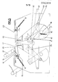
- the machine shown comprises a casing in the lateral flanges 1 of which are rotatably mounted, parallel to one another, two axes 2, 36 whose ends carry, integral with them, two pairs of pivoting arms 11, 27.
- L one of the pairs 27 longer than the other is connected by an operating handle tube 26.
- Each of the pairs of arms 11, 27 is also respectively braced above the casing by a tube carrying a folding blade, 12 for the arms 11 and 25 for the arms 27.
- two half-tables 17, 20 In a central upper opening of the casing are arranged two half-tables 17, 20 forming folding surfaces and stop for the planes to be folded as will be seen below.
- cams are also integral with respective levers 3a, 37a, the lever 3a carrying an articulation axis 6 of a latch 39 which has a coupling notch with a connecting finger 32 carried by the lever 37a, so that in the state of coupling of these levers, the two blade-carrying arms can be operated together using the operating handle 26.
- An unlocking lever 33 is articulated in the casing around an axis 33a, the individual support of which is not shown here, and it is provided with a central axis 38 of articulation of two levers 8, 30, whose free ends are in the form of a fork and cooperate with fingers 7, 31 integral with the levers 5, 34 for controlling the half-tables.
- the lever 33 extends projecting from the casing to be maneuverable at will by the user.
- the pressure members 14, 23 With the half-tables 17, 20 which form the folding and abutment surfaces, the pressure members 14, 23 extending above them cooperate and which are shaped as curved blades facing the half-tables and their vertical abutment rim. and inserted floating between supports 13, 13a and 24, 24a formed along the upper opening of the casing.
- These pressing members 14, 23 are respectively provided at their ends, around axes 14a, 23a which they carry, of articulated crutches 15, 22 of support cooperating with chairs 16, 21 attached to the internal wall of the flanges 1 of the casing.
- To these axes 14a, 23a are attached tension springs 10, 28 furthermore fixed on axes 9, 29 supported by the flanges 1 and also forming operating stops of the corresponding blade-holder arms 11, 27.
- the springs 10 and 28 are intended to keep the pressers 14 and 23 in constant abutment with the vertical edge of the half-tables 17 and 20, which guarantees their correct positioning. These springs are also used to bring the pressers down to ensure the initial formation of the fold and after that prevent the paper from escaping during the reverse movement of the blade.
- the end of the document to be folded can then be introduced between the front presser 23 and the corresponding half-table 20.
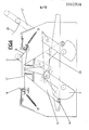
- the lever 33 is then raised manually by the operator so that, as illustrated in FIG. 4, the axis central 38 raises the levers 8 and 30 which, pushing the fingers 7 and 31, separate the levers 5, 34 for controlling the half-tables, which has the effect of raising them around their axis of oscillation.
- the half-table 20 thus jams the end of the document which has been engaged between it and the presser 23.
- This same movement guarantees the establishment of the abovementioned initial position of the pressers 14 and 23, in that 'it brings, by pressing the half-tables against the pressers, the crutches 15 and 22 to be effectively wedged on the chairs 16 and 21 as shown.
- the blade-carrying arm 27 with an operating handle 26 is then pushed backwards.
- the cam 37 which is integral therewith then comes to bear on the roller 35 and the lever 34, which has the effect of keeping the half-table 20 well pressed against the corresponding presser 23, thus preventing the corresponding end of the plane of slide.
- the lever 33 is released by the user, which allows the rear half-table 17 to lower, and thus save the space necessary for the introduction of the blade 25 when it comes push the document between the presser 14 and this rear half-table 17, at the end of the movement of the blade-holder arm 27 towards the rear. As illustrated in FIG.
- the front blade-holder arm 27 is brought back by the user towards him, and he drives in his return movement with him the rear blade-holder arm 11.
- the half-table 17 is in turn raised by the cam 3 which pushes the lever 5 for controlling the half-table 17 via the roller 3, so that the half-table 17 is in turn strongly applied against the presser 14 against which it keeps thus formed and tightened the fold which has just been established.
- the accumulation of thickness of the successive folds of the document called to be formed is absorbed by the inherent elasticity of the half-tables.
- auxiliary means intended in part to allow control or command at the foot of the machine further facilitating its control with both hands by the user.
- This additional system is constituted by means of a cam 40 mounted to rotate freely around the pivot axis 36 and provided with a return spring 42, interposed between it and the axis 36, while a cable 41 connects this cam 40 to a foot control pedal not shown.
Landscapes
- Folding Of Thin Sheet-Like Materials, Special Discharging Devices, And Others (AREA)
Priority Applications (1)
| Application Number | Priority Date | Filing Date | Title |
|---|---|---|---|
| AT82102767T ATE16691T1 (de) | 1981-04-03 | 1982-04-01 | Maschine zum falten von zeichnungen oder grossformatigen dokumenten. |
Applications Claiming Priority (2)
| Application Number | Priority Date | Filing Date | Title |
|---|---|---|---|
| FR8107005A FR2503112A1 (fr) | 1981-04-03 | 1981-04-03 | Plieuse manuelle silencieuse pour les plans et documents de grand format |
| FR8107005 | 1981-04-04 |
Publications (2)
| Publication Number | Publication Date |
|---|---|
| EP0062308A1 true EP0062308A1 (de) | 1982-10-13 |
| EP0062308B1 EP0062308B1 (de) | 1985-11-27 |
Family
ID=9257132
Family Applications (1)
| Application Number | Title | Priority Date | Filing Date |
|---|---|---|---|
| EP82102767A Expired EP0062308B1 (de) | 1981-04-03 | 1982-04-01 | Maschine zum Falten von Zeichnungen oder grossformatigen Dokumenten |
Country Status (5)
| Country | Link |
|---|---|
| US (1) | US4449963A (de) |
| EP (1) | EP0062308B1 (de) |
| AT (1) | ATE16691T1 (de) |
| DE (1) | DE3267652D1 (de) |
| FR (1) | FR2503112A1 (de) |
Cited By (1)
| Publication number | Priority date | Publication date | Assignee | Title |
|---|---|---|---|---|
| FR2944515A1 (fr) * | 2009-04-21 | 2010-10-22 | Chatel Reprographie | Dispositif de pliage debrayable |
Families Citing this family (1)
| Publication number | Priority date | Publication date | Assignee | Title |
|---|---|---|---|---|
| US20050208132A1 (en) * | 2002-07-29 | 2005-09-22 | Gayatri Sathyan | Methods and dosage forms for reducing side effects of benzisozazole derivatives |
Citations (1)
| Publication number | Priority date | Publication date | Assignee | Title |
|---|---|---|---|---|
| FR1098624A (fr) * | 1957-11-15 | 1955-08-16 | Machine à plier les plans |
Family Cites Families (3)
| Publication number | Priority date | Publication date | Assignee | Title |
|---|---|---|---|---|
| BE572783A (de) * | ||||
| US1877359A (en) * | 1929-12-12 | 1932-09-13 | West Disinfecting Co | Paper folding machine |
| US3496698A (en) * | 1966-06-06 | 1970-02-24 | William A Wichmann | Machine for cutting,folding and packaging strip material |
-
1981
- 1981-04-03 FR FR8107005A patent/FR2503112A1/fr active Granted
-
1982
- 1982-04-01 AT AT82102767T patent/ATE16691T1/de not_active IP Right Cessation
- 1982-04-01 DE DE8282102767T patent/DE3267652D1/de not_active Expired
- 1982-04-01 EP EP82102767A patent/EP0062308B1/de not_active Expired
- 1982-04-13 US US06/367,902 patent/US4449963A/en not_active Expired - Fee Related
Patent Citations (1)
| Publication number | Priority date | Publication date | Assignee | Title |
|---|---|---|---|---|
| FR1098624A (fr) * | 1957-11-15 | 1955-08-16 | Machine à plier les plans |
Cited By (1)
| Publication number | Priority date | Publication date | Assignee | Title |
|---|---|---|---|---|
| FR2944515A1 (fr) * | 2009-04-21 | 2010-10-22 | Chatel Reprographie | Dispositif de pliage debrayable |
Also Published As
| Publication number | Publication date |
|---|---|
| FR2503112A1 (fr) | 1982-10-08 |
| DE3267652D1 (en) | 1986-01-09 |
| EP0062308B1 (de) | 1985-11-27 |
| US4449963A (en) | 1984-05-22 |
| ATE16691T1 (de) | 1985-12-15 |
| FR2503112B1 (de) | 1983-07-01 |
Similar Documents
| Publication | Publication Date | Title |
|---|---|---|
| EP0808122B1 (de) | Spender von aufwischmaterial zur ausgabe in gefalzter oder in ungefalzter form | |
| EP0329580B1 (de) | Schaltgerät für Gemüse und Früchte | |
| FR2771275A1 (fr) | Instrument de nettoyage a tete a franges | |
| EP0278803A1 (de) | Klammer zum Aufhängen eines Gegenstandes | |
| FR2924009A1 (fr) | Coupe-legumes manuel permettant la decoupe de legumes en batonnets ou en cubes | |
| FR2571646A1 (fr) | Outil d'attache destine a fixer et a couper une bande d'attache | |
| EP0346177B1 (de) | Befestigungsvorrichtung für eine Platte oder ähnliches im inneren eines Rahmens | |
| WO2014118483A1 (fr) | Appareil distributeur de materiaux d'essuyage mis en forme pour etre en plusieurs plis en sortie de l'appareil | |
| FR2739546A1 (fr) | Appareil distributeur de materiau d'essuyage en fonctionnement automatique ou semi-automatique avec dispositif selecteur | |
| FR2604696A1 (fr) | Dispositif de coupe de ruban | |
| EP0925009B1 (de) | Verfahren und gerät zum öffnen von austern | |
| EP0062308B1 (de) | Maschine zum Falten von Zeichnungen oder grossformatigen Dokumenten | |
| FR2545463A1 (fr) | Appareil de collage de bandes | |
| EP0612476B1 (de) | Vorrichtung zur Herstellung von Sandwichs (belegten Broten) | |
| BE1005621A3 (fr) | Systeme de decoupe de papier pour siege de toilette. | |
| EP0398823A1 (de) | Schneidevorrichtung für einen automatischen Spender von Aufwischmaterial, das aus schmalen, im Zickzack gefaltenen Bändern besteht | |
| EP0491412B1 (de) | Vorrichtung zum Fixieren eines Elementes in ein Gestell | |
| FR2525949A1 (fr) | Machine a agrafer des moulures pour realiser des cadres d'encadrement de tableaux et objets analogues | |
| FR2686236A1 (fr) | Machine presse-agrumes. | |
| EP0018275A1 (de) | Scheibenschneidmaschine | |
| EP0320342B1 (de) | Abkantbank | |
| WO2001056433A1 (fr) | Dispositif destine a l'ouverture des coquillages bivalves tels que les huitres | |
| BE572783A (de) | ||
| FR2852534A1 (fr) | Plieuse de tole | |
| EP0030061A2 (de) | Brotschneidemaschine |
Legal Events
| Date | Code | Title | Description |
|---|---|---|---|
| PUAI | Public reference made under article 153(3) epc to a published international application that has entered the european phase |
Free format text: ORIGINAL CODE: 0009012 |
|
| AK | Designated contracting states |
Designated state(s): AT BE CH DE GB IT LI LU NL SE |
|
| 17P | Request for examination filed |
Effective date: 19830407 |
|
| RAP1 | Party data changed (applicant data changed or rights of an application transferred) |
Owner name: S.A.R.L. CHAPEL REPROGRAPHIE |
|
| ITF | It: translation for a ep patent filed | ||
| GRAA | (expected) grant |
Free format text: ORIGINAL CODE: 0009210 |
|
| AK | Designated contracting states |
Designated state(s): AT BE CH DE GB IT LI LU NL SE |
|
| REF | Corresponds to: |
Ref document number: 16691 Country of ref document: AT Date of ref document: 19851215 Kind code of ref document: T |
|
| REF | Corresponds to: |
Ref document number: 3267652 Country of ref document: DE Date of ref document: 19860109 |
|
| PGFP | Annual fee paid to national office [announced via postgrant information from national office to epo] |
Ref country code: AT Payment date: 19860429 Year of fee payment: 5 |
|
| PG25 | Lapsed in a contracting state [announced via postgrant information from national office to epo] |
Ref country code: LU Free format text: LAPSE BECAUSE OF NON-PAYMENT OF DUE FEES Effective date: 19860430 |
|
| PLBE | No opposition filed within time limit |
Free format text: ORIGINAL CODE: 0009261 |
|
| STAA | Information on the status of an ep patent application or granted ep patent |
Free format text: STATUS: NO OPPOSITION FILED WITHIN TIME LIMIT |
|
| 26N | No opposition filed | ||
| PG25 | Lapsed in a contracting state [announced via postgrant information from national office to epo] |
Ref country code: AT Effective date: 19870401 |
|
| PGFP | Annual fee paid to national office [announced via postgrant information from national office to epo] |
Ref country code: NL Payment date: 19870430 Year of fee payment: 6 |
|
| PG25 | Lapsed in a contracting state [announced via postgrant information from national office to epo] |
Ref country code: SE Effective date: 19880402 |
|
| PG25 | Lapsed in a contracting state [announced via postgrant information from national office to epo] |
Ref country code: LI Effective date: 19880430 Ref country code: CH Effective date: 19880430 |
|
| BERE | Be: lapsed |
Owner name: S.A.R.L. CHAPEL REPROGRAPHIE Effective date: 19880430 |
|
| PG25 | Lapsed in a contracting state [announced via postgrant information from national office to epo] |
Ref country code: NL Effective date: 19881101 |
|
| PG25 | Lapsed in a contracting state [announced via postgrant information from national office to epo] |
Ref country code: GB Free format text: LAPSE BECAUSE OF NON-PAYMENT OF DUE FEES Effective date: 19881121 |
|
| GBPC | Gb: european patent ceased through non-payment of renewal fee | ||
| NLV4 | Nl: lapsed or anulled due to non-payment of the annual fee | ||
| REG | Reference to a national code |
Ref country code: CH Ref legal event code: PL |
|
| PG25 | Lapsed in a contracting state [announced via postgrant information from national office to epo] |
Ref country code: DE Effective date: 19890103 |
|
| PG25 | Lapsed in a contracting state [announced via postgrant information from national office to epo] |
Ref country code: BE Effective date: 19890430 |
|
| EUG | Se: european patent has lapsed |
Ref document number: 82102767.9 Effective date: 19890726 |