EP0062317A1 - Procédé de travail plastique de matériaux métalliques - Google Patents
Procédé de travail plastique de matériaux métalliques Download PDFInfo
- Publication number
- EP0062317A1 EP0062317A1 EP82102795A EP82102795A EP0062317A1 EP 0062317 A1 EP0062317 A1 EP 0062317A1 EP 82102795 A EP82102795 A EP 82102795A EP 82102795 A EP82102795 A EP 82102795A EP 0062317 A1 EP0062317 A1 EP 0062317A1
- Authority
- EP
- European Patent Office
- Prior art keywords
- temperature
- condition
- plastic
- metallographical
- sudden change
- Prior art date
- Legal status (The legal status is an assumption and is not a legal conclusion. Google has not performed a legal analysis and makes no representation as to the accuracy of the status listed.)
- Granted
Links
Images




Classifications
-
- C—CHEMISTRY; METALLURGY
- C21—METALLURGY OF IRON
- C21D—MODIFYING THE PHYSICAL STRUCTURE OF FERROUS METALS; GENERAL DEVICES FOR HEAT TREATMENT OF FERROUS OR NON-FERROUS METALS OR ALLOYS; MAKING METAL MALLEABLE, e.g. BY DECARBURISATION OR TEMPERING
- C21D11/00—Process control or regulation for heat treatments
-
- B—PERFORMING OPERATIONS; TRANSPORTING
- B21—MECHANICAL METAL-WORKING WITHOUT ESSENTIALLY REMOVING MATERIAL; PUNCHING METAL
- B21C—MANUFACTURE OF METAL SHEETS, WIRE, RODS, TUBES, PROFILES OR LIKE SEMI-MANUFACTURED PRODUCTS OTHERWISE THAN BY ROLLING; AUXILIARY OPERATIONS USED IN CONNECTION WITH METAL-WORKING WITHOUT ESSENTIALLY REMOVING MATERIAL
- B21C51/00—Measuring, gauging, indicating, counting, or marking devices specially adapted for use in the production or manipulation of material in accordance with subclasses B21B - B21F
-
- B—PERFORMING OPERATIONS; TRANSPORTING
- B21—MECHANICAL METAL-WORKING WITHOUT ESSENTIALLY REMOVING MATERIAL; PUNCHING METAL
- B21J—FORGING; HAMMERING; PRESSING METAL; RIVETING; FORGE FURNACES
- B21J5/00—Methods for forging, hammering, or pressing; Special equipment or accessories therefor
- B21J5/06—Methods for forging, hammering, or pressing; Special equipment or accessories therefor for performing particular operations
- B21J5/08—Upsetting
-
- B—PERFORMING OPERATIONS; TRANSPORTING
- B21—MECHANICAL METAL-WORKING WITHOUT ESSENTIALLY REMOVING MATERIAL; PUNCHING METAL
- B21J—FORGING; HAMMERING; PRESSING METAL; RIVETING; FORGE FURNACES
- B21J9/00—Forging presses
- B21J9/02—Special design or construction
- B21J9/06—Swaging presses; Upsetting presses
- B21J9/08—Swaging presses; Upsetting presses equipped with devices for heating the work-piece
-
- C—CHEMISTRY; METALLURGY
- C21—METALLURGY OF IRON
- C21D—MODIFYING THE PHYSICAL STRUCTURE OF FERROUS METALS; GENERAL DEVICES FOR HEAT TREATMENT OF FERROUS OR NON-FERROUS METALS OR ALLOYS; MAKING METAL MALLEABLE, e.g. BY DECARBURISATION OR TEMPERING
- C21D7/00—Modifying the physical properties of iron or steel by deformation
- C21D7/13—Modifying the physical properties of iron or steel by deformation by hot working
Definitions
- This invention relates to methods of thermal plastic working of metal materials.
- the temperature of a metal material causing the material to start effecting metallographical changes depends not only upon its constituent elements to a slight degree, but also upon its history of heat-treatment or other kind of processing and its rate of heating or cooling until the foregoing temperature may be reached. Also, when metal materials are heated or cooled for a relatively-shorter period of time in an industrial scale, the conventional method of measuring the material temperatures during treatment is subject to such disadvantages as delays or errors in measurement; that is, it is not easy for the conventional method to maintain the uniform conditions of measurement of the material temperature. For example, when the temperature of metal materials is measured by using a radiation pyrometer, the rate of radiation to the pyrometer may be varied according to the particular surface condition of the material. Also, when such a measurement is made by using a thermocouple- type thermometer, the measurement may be affected by the particular connection of the thermometer to the - material.
- the temperature range of a metal material producing the condition of superplasticity is relatively smaller; therefore, when the material reaches such a temperature, it is not easy to start processing the material in such a timely manner as enables the desired plastic working of the material. This difficulty has prevented the nature of superplasticity of metal materials from being fully utilized in the plastic working thereof in an industrial mass production.
- the primary object of the invention is to provide a method of plastic working of metal materials whereby a metal material, when having reached the temperature producing the superplastic condition thereof, is plastically worked in such a timely manner as enables the desired processing of the material so that the processing efficiency thereof is greatly increased.
- Another object of the invention is to provide a method of plastic working of metal materials whereby the above-mentioned timely working of the material is made with a great degree of easiness and forming accuracy without being affected by any internal factors such as the chemical composition or history of heat treatment or other kind of processing thereof or any external factors such as those related to the measurement of temperature of the material.
- a metal material 1 such as steel or the like is held at its both ends by a pair of chucks 2 and 4 connected to a fixed object 3 and a tension or stretching means 5, respectively. Both chucks 2 and 4 are designed to apply an electric current to the material 1.
- the stretching means 5 is provided with a piston 6 adapted to move, in a direction indicated by an arrow, by oil under pressure entering a chamber of the means 5 through a oil-supply port 7, so that the chuck 4 is moved in the same direction.
- the chucks 2 and 4 are also connected to an electric- power source or material-heating source 8 which is adapted to supply the chucks 2 and 4 with electric energy and connected to a circuit 9 for controlling the power supplied from the power source 8 to the material 1 through the chucks 2 and 4.
- Numeral 10 designates a means for observing metallographical changes effected in the workpiece 1, such as magnetic sensor for measuring the magnetic permeability of the workpiece 1.
- Numeral 10' designates a circuit for detecting the points of changes in magnetic property of the workpiece 1.
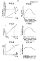
- the metal material 1 is plastically worked, e.g., stretch-formed by the arrangement of Fig. 1 as follows: First the power 8 is turned on to heat the material 1. As the material 1 is increased in temperature by the . heating, the magnetic permeability of the material is also varied, and the permeability is measured from time to time or continuously by the magnetic sensor 10. And when such a sudden change in the permeability as indicated by AC l in Fig. 2 is detected, the control circuit 9 is operated to turn off the power 8 so as to stop heating the material 1, and the stretch means 5 is operated to stretch-form the material 1.
- the sudden change in the permeability of the material may be detected, for example, as follows:
- the permeability-detecting signals (Fig. 3 (A)) are differentiated in the detection circuit 10' so that differential waveforms as shown in Fig. 3 (B) are obtained, and when any differential waveform exceeds the predetermined level V I , the exceeding waveform indicates that the sudden change has been effected.
- the operation of the stretch means 5 may be started in such a timely manner as enables the plastic working of the material in the superplastic condition thereof, so that the working efficiency is greatly increased.
- the power supply to the material may not be stopped immediately, but continued for some little time so that the material is stretch-formed at a temperature slightly increased from that at the time when the sudden change has been detected.
- a metal material 1 is inserted through an electric furnace 11 and heated by heaters 12 provided in the furnace 11, and during heating, the damping factor or capacity of ultrasonic (supersonic) waves of the material 1 is measured by a supersonic flaw detector 13 protected against heat by water flowing through a pair of protection pipes 14 in directions indicated by arrows.
- the steels of each group were further supplied with electric current, without interruption of the supply between the detection of sudden change, in a different amount and for a different period of time from those of the steels of the other groups. Then the current supply was stopped, and the steels of each group were rapidly stretched at a rate of 250 mm/sec. by different distances of 50 to 1,000 mm. by pulling the chuck 4, holding one end of the steel, in the left-hand direction of Fig. 1. As a result, in each group, one or more of the steels thus stretched were uniformly reduced in diameter at its entire length, while the other steel or steels were not given such a result.
- Fig. 11 The foregoing measurements of temperatures are shown in Fig. 11 where C indicates a point of the value of (second-differential value of temperature relative to the time elapsed) changing from positive to negative. A certain period of time after the point C had been detected, the bar was stretched in the same manner as in the preceding Examples. As a result, it was found that the bar may be stretch-formed with no rupture by starting to stretch it with a certain period of time lapsed after the point C has been detected.
- Fig. 12 shows the probability of rupture of workpieces, with an indication that no probability of rupture of the workpieces exists in some points of time.
- an additional amount of temperature AT was set as a heat to be applied to the bar after the sudden change D has been detected, although the additional temperature ⁇ T for each group of materials was determined in a different amount or degree from those in the other groups.
- such an additional amount of heat was applied to each material, and the distance between the two chucks was increased by 400 mm. so that the material (bar) was stretched.
- one or more of the steels were uniformly reduced in diameter at its entire length (length of 800 mm. located in the furnace, however), and the maximum uniform reduction of diameter in each group was compared with those of the other groups.
- Fig. 13 The measurements of maximum reductions in diameter are shown in Fig. 13 from which it is seen that the temperature of the bar should be maintained in a certain range, after a sudden change has been detected in the damping factor, in order to obtain the maximum uniform reduction in diameter.
- a temperature detector 20 shown by a two- dotted line in Fig. 1, to the arrangement of Fig. 1.
- the detector 20 may be a radiation pyrometer or any other suitable means for measuring the temperature of the metal 1.
- Fig. 14 when a sudden change in the magnetic property of the material 1 is detected by the sensor 10, the temperature T 1 of the material 1 determined by the detector 20 at that time is taken to be a reference temperature (Fig. 14). After the reference temperature is thus obtained, a slight amount of energy is further supplied to the material 1, e.g., by controlling the optimum-processing temperature control circuit 9 to cause the power source 8 to further supply the material with electric energy.
- the amount of the additional energy to be supplied depends upon the particular kind, dimensions, and processing conditions of the material, and this additional amount is set in the control circuit 9 in advance. It is to be noted that the additional amount of energy to be supplied after the sudden change is also varied according to the method of supply (e.g., rapid supply for a shorter period of time, slow supply for a longer period of time, or the like).
- the control circuit 9 is so operated as to stop the source 8 supplying the electric current to the material.
- the material 1 thus having obtained the foregoing optimum temperature is then stretch-formed by operating the stretch means 5.
- the stretch forming of the material is performed most readily owing to the foregoing condition of the material.
- optimum temperature of different metal materials may be different from those of the other materials according to the particular kind and chemical composition of the material and/or particular variations effected in the material:; however, according to the method herein, any.particular kind of metal material heat-treated in particular conditions is allowed to reach the particular optimum plastic-working temperature of its own. with exact. accuracy, followed by the most-timely working thereof.
- any one of the following methods may be used:
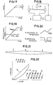
- FIG. 18 provides a method of detecting a sudden change in the metallographical condition of metal materials by differentiating the measurements of the material temperature. That is, a metal material 1 is heated by receiving a constant supply of electric current: from a power source 8 for a certain period of time (Fig. 19), while the material temperature varied by the:heating as shown in Fig. 19 is measured.
- a sudden change as shown in Fig. 19 (which is also shown in an enlarged view of Fig.
- the signal having measured the sudden change is differentiated in a circuit 9 for controlling the optimum temperature of metal material for the plastic working thereof, so that such a signal as shown in Fig. 20(B) is obtained as detecting the sudden change in the material temperature.
- the temperature of the material determined by the detector at the time of sudden change is taken to be a reference temperature T l , and the supply of electric current to the material is further continued until an additional amount of increase AT in temperature from the reference temperature is detected by the detector 20, so that the workpiece 1 is allowed to reach the optimum temperature T 2 for the plastic working thereof.
- the foregoing method of plastic working may be employed, for example, for the production of such a taper rod as shown in Fig. 21.
- the taper rod of Fig. 21 has tapered portions b, b, on both sides of a central thicker section a, which are gradually decreased in diameter towards the rod ends.
- Such a taper rod may be coiled to produce a spring to be used in the produciton of cushions for automobiles or railway vehicles.
- a coil spring is characterized in that the height (or length) of the spring is not varied proportional to the load on the spring. Therefore, such a coil spring provides more comfort in the riding in vehicles than the conventional spring having a proportional correlation between the load thereon and the height thereof as indicated by Fig. 22(B).
- a piece of rolled steel or other kind of metal 21 is supplied from a reel (not shown) in a direction indicated by an arrow, and is taken hold of by a fixed chuck 22, stretch chuck 23, and a pair of energizing chucks 24 and 25.
- the material 1 is then heated by operating the heating source 26 to supply electric current to the material through the chucks24 and 25 (Fig. 24(A)).
- the heating source 26 to supply electric current to the material through the chucks24 and 25 (Fig. 24(A)).
- the metallographical condition is observed, and when a sudden change in the condition is detected as shown in Fig. 24(B), the optimum temperature for the plastic working of the material is reached by supplying an additional amount of thermal energy to the material, as previously mentioned (Fig. 24(C)).
- the additional supply of thermal energy (electric current in Fig. 23) to the material is stopped.
- the temperature of the material in the lengthwise or axial direction thereof is controlled (Fig. 24(D)) by using air-nozzle blocks 27, 28, and 29 which each have a plurality of nozzles 31 directed to the material to blow cooling gases (e.g., pressurized air) against the material.
- the cooling gas is supplied from a supply means (not shown) to a supply port 30.
- the blocks 27, 28, and 29 each are provided in number more than one, and each group of blocks is so located as to surround the material by all blocks.
- the blocks 27, 28, and 29 each may be one block shaped in an annular manner so that the block surrounds the material in a continuous manner.
- the nozzles 31 of the blocks 27 and 29 closer to the energizing chucks 24 and 25, respectively, are adapted to blow more amount of cooling gases than those of them further from the chucks 24 and 25, respectively.
- the material With the cooling gases blown against the material from the air nozzles 31 (although no gases may be blown off from the nozzles 31 of the central blocks 28), the material is provided with a temperature pattern in the axial direction thereof (Fig. 24(D)), so that the material is given a plasticity gradient.
- the production of temperature pattern may be started before the optimum-temperature control (Fig. 24(C)) is finished (as indicated by a dotted line of Fig. 24(D)).
- the plastic working thereof is started (Fig. 24(E)) by pulling the stretch chuck 23 in the right-hand direction of Fig. 23 to stretch-form the material in its axial direction, so that the material is allowed to elongate with different percentages of different portions thereof according to their different plastic workability (or different percentages of elongation of theidifferent portions according to the gradient of deformation resistance). Then such a taper rod as shown in Fig. 23 is obtained which has tapered portions b each decreasing gradually in diameter in one direction. It is to be noted that such a plastic working of the material may be started before the production of temperature pattern of the material (Fig. 24(D)) is finished.
- the rod of the same Fig. may be provided, in a repeated manner, with a number of sections comprising a largest-diameter portion a, tapered portion b, and smallest-diameter portion c by repeating the foregoing operation. And the sections formed into the same shape are cut by a cutter 35 so that the required rods are obtained.
- P 1 designates a pitch of elongation of the material obtained by a single pulling or stretching operation
- P 2 designates a pitch of cutting the rod sections shaped.
- a temperature of a portion or portions of the material may be made lower than that of the portion having the greatest plastic workability, as previously mentioned. Also the same purpose may be achieved by making higher the temperature of such a portion than that of the most plastic workable portion.
- the temperature gradient of the material for the same purpose may be produced by heating the material in such a manner that the predetermined gradient is formed . in the axial direction of the material, instead of cooling the material heated. Such a heat treatment of the material may be made by such methods as follows:
- the pattern of temperature gradient to be given to the material for providing different portions thereof with different plastic workability depends upon the particular kind of material, dimensions, heating temperature used and stretch conditions of the material and the particular tapered shape to be obtained; therefore, no comprehensive suggestion may be made of the pattern of temperature gradient, but it must be determined for each specific case.
- Figs. 25(A) and (B) show examples of the pattern which may be used in some cases.
- the metal material provided with the pattern of temperature gradient is subjected to a stretching or tensile force in such a manner that the material is given the distortion rate which has been usually predetermined according to the quality (alloy composition) and shape of the material and the dimensions before the stretch forming and those to be obtained by the stretch forming of the material.
- a stretching or tensile force in such a manner that the material is given the distortion rate which has been usually predetermined according to the quality (alloy composition) and shape of the material and the dimensions before the stretch forming and those to be obtained by the stretch forming of the material.
- any other method of applying the tensile force to the material may be employed if required for the particular tapered shape to be obtained.
- the speed of stretching the material for the required plastic forming thereof may not be maintained constant so that the predetermined distortion rate is obtained, but the stretching speed may be varied between the starting and finishing of the stretching so as to achieve the same purpose.
- the foregoing method of tapering a metal material may be employed not only for a continuous material, but for a material of limited length in which to form one or two taper portions.
- taper rods made by the foregoing method may be employed for the production of taper-coil springs with great advantages, as previously mentioned. Also these rods may be used as materials of antennas. Moreover, if the rods are of a hollow metal material, they may.be used as materials of ski sticks or street-light poles. And a wider variety of uses thereof may be possible.
- a metal material 21 is heated by supplying electric current to the material from the power source 26 in the axial direction of the material (Figs. 26(A) and (B)).
- the current supply to the material is made for a period of time indicated by t 1 of Fig. 26(B).
- t 1 of Fig. 26(B) the temperature of the material is increased, at the entire length thereof, up to T 11 which is lower than the predetermined working temperature mentioned hereafter (Fig. 27-l(a)A).
- the material is cooled for a period of time indicated by t 2 of Fig. 26(C) by blowing cooling gases against the material from the air nozzles 31 (although the central nozzles 31 may or may not blow cooling gases), so that the material is given a slight gradient of temperature in its axial direction as shown in Fig. 27-1(a)B.
- the temperature gradient or differences of temperatures of different portions of the material give a pattern of electrical resistance of the material as shown in Fig. 27-1(b) .
- the material is again heated, as indicated by t 3 . of Figs. 26(A) and (B), by supplying electric current to the material in which portions of higher temperature have higher electrical resistances, while those of lower temperature have lower electrical resistances.
- the current supply to the material is made in the same direction as those of temperature gradient or axial' direction of the material, so that portions of different electrical resistance are related to each other in series. Therefore, the portions of higher electrical resistance is increased in temperature to a higher degree, generating a greater amount of heat, than those of lower electrical resistances, so that the temperature gradient of the material is varied to that of Fig. 27-l(c), after lapse of a certain period of time, which temperature gradient is of the optimum temperature of the material for the plastic working thereof.
- the temperature pattern given to the material by the foregoing cooling treatment is to be set by experiment or calculation so that the different electrical resistances of different portions of the material determined by the pattern produce the suitable temperature pattern of Fig. 27-l(c) after current supplies to shown in Fig. 26 all have been made to the material.
- the predetermined amount of electric current When the predetermined amount of electric current has been supplied to the material for the predetermined period of time, it may be detected by the completion (of the current supply) itself whether the material has reached the optimum temperature for the plastic working thereof.
- the following method may be used for the same purpose: A sudden change in the metallographical condition of the material is detected (Fig. 26(D)), preferably in the portion of the material to be given the most plastic-workable condition, such as the central portion thereof.
- the control for optimum temperature for plastic working is made in the same manner as before so that the material reaches the predetermined plastic-working temperature with the predetermined gradient (Fig. 26(E)).
- Fig. 28 shows a procedure of producing a taper rod similar to that of Fig. 26, but different therefrom in some operational timings. According to this procedure, when the material is being still heated, the cooling thereof is started so that both treatments are made simultaneously from the middle of the heat treatment. This method is advantageous in that the required period to of time for a series of operations is shortened.
- cooling means includes a plurality of air nozzles 33 for blowing cooling gases (e.g., pressurized air) against the material 21, which gases have been supplied from a supply-means (not shown) to supply ports 34.
- the nozzles 33 closer to the energizing chucks 24 or 25 are adapted to receive and blow off a more amount of cooling gas than those further from them.
- a still another embodiment of workpiece-cooling means includes a pair of cylindrical walls 36 of tapered shape having an open end for the workpiece 21.
- the other or closed end of each wall 36 is provided with a supply port 37.
- cooling gases are supplied into the wall 36 from the port 37, and then the gas is allowed to flow between the wall and the material (inserted therein) in such a manner that the gas stream moves at a rapid rate in the smaller-diameter section of the wall, while the stream moves at a slow rate in the larger-diameter section. Therefore the material is cooled to a higher degree in the smaller-diameter section and to a smaller degree in the other section of the wall.
- the gas stream is then allowed to come out of the open end of the wall.
- a portion 21a to be left as having a larger diameter is of the largest thickness, while a portion 21b to be made into the most slender portion is of the smallest thickness (in some cases, having no thickness)
- the remaining section between the two extremes is given such a thickness as corresponds to the reduction in diameter predetermined as one to be obtained after the elongation forming.
- the distribution of temperature of the layer 40 is such that the surface of the portion 21a is of the lowest temperature, and the temperature is increased towards both rod axis and portion 21b.
- the material is elongated in its axial direction with the different portions thereof elongated in different amounts according to the thickness of the layer 40 in the particular different portion. As a result, a taper rod is obtained which is gradually decreased in diameter.
Landscapes
- Engineering & Computer Science (AREA)
- Chemical & Material Sciences (AREA)
- Mechanical Engineering (AREA)
- Crystallography & Structural Chemistry (AREA)
- Materials Engineering (AREA)
- Metallurgy (AREA)
- Organic Chemistry (AREA)
- Physics & Mathematics (AREA)
- Thermal Sciences (AREA)
- Forging (AREA)
Priority Applications (1)
| Application Number | Priority Date | Filing Date | Title |
|---|---|---|---|
| AT82102795T ATE15077T1 (de) | 1981-04-06 | 1982-04-02 | Verfahren zur plastischen bearbeitung von metallischen materialien. |
Applications Claiming Priority (6)
| Application Number | Priority Date | Filing Date | Title |
|---|---|---|---|
| JP51498/81 | 1981-04-06 | ||
| JP5149881A JPS57165150A (en) | 1981-04-06 | 1981-04-06 | Plastic working method |
| JP7268181A JPS57187110A (en) | 1981-05-14 | 1981-05-14 | Manufacture of tapered rod |
| JP72681/81 | 1981-05-14 | ||
| JP116688/81 | 1981-07-24 | ||
| JP11668881A JPS5816728A (ja) | 1981-07-24 | 1981-07-24 | 被加工材の塑性加工方法 |
Publications (2)
| Publication Number | Publication Date |
|---|---|
| EP0062317A1 true EP0062317A1 (fr) | 1982-10-13 |
| EP0062317B1 EP0062317B1 (fr) | 1985-08-21 |
Family
ID=27294340
Family Applications (1)
| Application Number | Title | Priority Date | Filing Date |
|---|---|---|---|
| EP82102795A Expired EP0062317B1 (fr) | 1981-04-06 | 1982-04-02 | Procédé de travail plastique de matériaux métalliques |
Country Status (4)
| Country | Link |
|---|---|
| US (1) | US4407682A (fr) |
| EP (1) | EP0062317B1 (fr) |
| AU (1) | AU546437B2 (fr) |
| DE (1) | DE3265543D1 (fr) |
Cited By (2)
| Publication number | Priority date | Publication date | Assignee | Title |
|---|---|---|---|---|
| FR2594145A1 (fr) * | 1986-02-13 | 1987-08-14 | Stein Heurtey | Procede de traitements mecaniques et thermochimiques des metaux |
| CN120055058A (zh) * | 2025-04-23 | 2025-05-30 | 山西路桥建设集团有限公司 | 一种钢绞线生产拉丝机及其使用方法 |
Families Citing this family (7)
| Publication number | Priority date | Publication date | Assignee | Title |
|---|---|---|---|---|
| US5033720A (en) * | 1988-06-28 | 1991-07-23 | China Steel Corporation | Apparatus for determining metal properties |
| JPH08210965A (ja) * | 1995-02-06 | 1996-08-20 | Honda Motor Co Ltd | 超塑性成形品のキャビティ計測方法 |
| DE19604408C1 (de) * | 1996-02-07 | 1997-05-28 | Allevard Federn Gmbh | Verfahren zur Herstellung von Schraubenfedern aus bikonischem Draht |
| UA77951C2 (en) * | 2000-11-29 | 2007-02-15 | Laminate for packaging of food and method for its formation (variants) | |
| US7049548B1 (en) | 2005-03-21 | 2006-05-23 | The Boeing Company | System and method for processing a preform vacuum vessel to produce a structural assembly |
| US7431196B2 (en) * | 2005-03-21 | 2008-10-07 | The Boeing Company | Method and apparatus for forming complex contour structural assemblies |
| US9658297B2 (en) * | 2015-01-05 | 2017-05-23 | The Boeing Company | Magnetic permeability measurement of ferromagnetic wires |
Citations (7)
| Publication number | Priority date | Publication date | Assignee | Title |
|---|---|---|---|---|
| FR481800A (fr) * | 1915-06-15 | 1917-01-16 | Leeds & Northrup Co | Procédé de détermination du moment oÙ des métaux passent par un point critique au cours d'un traitement par la chaleur auquel on les soumet pour la trempe, l'affinage ou la recuisson |
| US1861687A (en) * | 1929-09-03 | 1932-06-07 | Hevi Duty Electric Co | Magnetic control system |
| GB756141A (en) * | 1951-11-05 | 1956-08-29 | Andre Huet | Improvements in the manufacture of tubular elements |
| LU58979A1 (fr) * | 1969-06-27 | 1969-11-12 | ||
| US3723194A (en) * | 1972-02-17 | 1973-03-27 | Republic Steel Corp | Method of providing superplastic steel and of producing articles by deformation thereof |
| FR2288786A1 (fr) * | 1974-10-25 | 1976-05-21 | Centre Techn Ind Mecanique | Procede et machine pour le traitement de pieces elancees en vue d'ameliorer leur structure interne et/ou pour les dresser |
| FR2477914A1 (fr) * | 1980-03-17 | 1981-09-18 | Daido Steel Co Ltd | Procede et appareil pour la fabrication de tiges coniques |
Family Cites Families (5)
| Publication number | Priority date | Publication date | Assignee | Title |
|---|---|---|---|---|
| US2059976A (en) * | 1931-09-04 | 1936-11-03 | Gillette Safety Razor Co | Apparatus for treating metal |
| US3130363A (en) * | 1960-06-08 | 1964-04-21 | United States Steel Corp | Apparatus for determining the magnetic condition of steel strip during continuous annealing |
| US3247364A (en) * | 1962-08-29 | 1966-04-19 | United States Steel Corp | Apparatus for measuring temperature differences |
| SU474564A1 (ru) * | 1973-05-25 | 1975-06-25 | Ордена Ленина И Ордена Трудового Красного Знамени Институт Электросварки Им.Е.О.Патона | Способ термомеханической обработки сварных соединений низколегированной стали |
| JPS5344125A (en) * | 1976-10-05 | 1978-04-20 | Canon Inc | Electronic calculator with time counting unit |
-
1982
- 1982-03-26 AU AU81945/82A patent/AU546437B2/en not_active Ceased
- 1982-03-29 US US06/363,345 patent/US4407682A/en not_active Expired - Fee Related
- 1982-04-02 EP EP82102795A patent/EP0062317B1/fr not_active Expired
- 1982-04-02 DE DE8282102795T patent/DE3265543D1/de not_active Expired
Patent Citations (7)
| Publication number | Priority date | Publication date | Assignee | Title |
|---|---|---|---|---|
| FR481800A (fr) * | 1915-06-15 | 1917-01-16 | Leeds & Northrup Co | Procédé de détermination du moment oÙ des métaux passent par un point critique au cours d'un traitement par la chaleur auquel on les soumet pour la trempe, l'affinage ou la recuisson |
| US1861687A (en) * | 1929-09-03 | 1932-06-07 | Hevi Duty Electric Co | Magnetic control system |
| GB756141A (en) * | 1951-11-05 | 1956-08-29 | Andre Huet | Improvements in the manufacture of tubular elements |
| LU58979A1 (fr) * | 1969-06-27 | 1969-11-12 | ||
| US3723194A (en) * | 1972-02-17 | 1973-03-27 | Republic Steel Corp | Method of providing superplastic steel and of producing articles by deformation thereof |
| FR2288786A1 (fr) * | 1974-10-25 | 1976-05-21 | Centre Techn Ind Mecanique | Procede et machine pour le traitement de pieces elancees en vue d'ameliorer leur structure interne et/ou pour les dresser |
| FR2477914A1 (fr) * | 1980-03-17 | 1981-09-18 | Daido Steel Co Ltd | Procede et appareil pour la fabrication de tiges coniques |
Cited By (2)
| Publication number | Priority date | Publication date | Assignee | Title |
|---|---|---|---|---|
| FR2594145A1 (fr) * | 1986-02-13 | 1987-08-14 | Stein Heurtey | Procede de traitements mecaniques et thermochimiques des metaux |
| CN120055058A (zh) * | 2025-04-23 | 2025-05-30 | 山西路桥建设集团有限公司 | 一种钢绞线生产拉丝机及其使用方法 |
Also Published As
| Publication number | Publication date |
|---|---|
| AU546437B2 (en) | 1985-08-29 |
| US4407682A (en) | 1983-10-04 |
| EP0062317B1 (fr) | 1985-08-21 |
| DE3265543D1 (en) | 1985-09-26 |
| AU8194582A (en) | 1982-11-25 |
Similar Documents
| Publication | Publication Date | Title |
|---|---|---|
| US6077369A (en) | Method of straightening wire rods of titanium and titanium alloy | |
| EP0062317B1 (fr) | Procédé de travail plastique de matériaux métalliques | |
| US4088511A (en) | Steels combining toughness and machinability | |
| CA1039159A (fr) | Aciers et methode de production connexe | |
| US4842818A (en) | Method for manufacturing tapered rods | |
| JPH11503491A (ja) | 例えば高合金鋼又は過共折鋼から成る棒材又は管材等の熱間仕上げの延伸された製品の製造方法 | |
| US4407486A (en) | Method and apparatus of hot working metal with induction reheating | |
| JPS6312690B2 (fr) | ||
| JP4018331B2 (ja) | ダブルテーパ鋼線と、その連続熱処理方法および装置 | |
| JPS6032529B2 (ja) | テ−パ−材の製造方法並びにその装置 | |
| RU2081189C1 (ru) | Способ термической обработки проката | |
| JP2002282982A (ja) | ダブルテーパばね鋼線の製造方法と装置 | |
| US4362578A (en) | Method of hot working metal with induction reheating | |
| JPH06346146A (ja) | 冷間成形コイルばね用線材の製造方法と装置 | |
| EP0054343B1 (fr) | Procédé et dispositif pour la fabrication de barres coniques | |
| JPH04272135A (ja) | 線及び棒材料を圧延する方法及び装置 | |
| Michel et al. | Thermomechanical finite element analysis (FEA) of spin extrusion | |
| US20070128443A1 (en) | Method for altering the shape of a tube | |
| Mariana et al. | Thermomechanical analysis of plastic deformation behaviour in dieless drawing of metallic materials | |
| RU2173598C2 (ru) | Способ изготовления раскатных кольцевых заготовок из высоколегированных сплавов | |
| GB2624983A (en) | Physical simulation method for forging process of nickel-based superalloy | |
| JPH0881713A (ja) | 直接通電加熱による鋼中炭化物の球状化法 | |
| SU1527284A1 (ru) | Способ изготовлени стальных изделий | |
| JPS5978716A (ja) | 段つきの棒または管を製造する方法 | |
| JPH0931540A (ja) | プレストレストコンクリート用鋼棒の製造方法 |
Legal Events
| Date | Code | Title | Description |
|---|---|---|---|
| PUAI | Public reference made under article 153(3) epc to a published international application that has entered the european phase |
Free format text: ORIGINAL CODE: 0009012 |
|
| AK | Designated contracting states |
Designated state(s): AT BE CH DE FR GB IT LU NL SE |
|
| 17P | Request for examination filed |
Effective date: 19821221 |
|
| ITF | It: translation for a ep patent filed | ||
| GRAA | (expected) grant |
Free format text: ORIGINAL CODE: 0009210 |
|
| AK | Designated contracting states |
Designated state(s): AT BE CH DE FR GB IT LI LU NL SE |
|
| REF | Corresponds to: |
Ref document number: 15077 Country of ref document: AT Date of ref document: 19850915 Kind code of ref document: T |
|
| REF | Corresponds to: |
Ref document number: 3265543 Country of ref document: DE Date of ref document: 19850926 |
|
| ET | Fr: translation filed | ||
| PGFP | Annual fee paid to national office [announced via postgrant information from national office to epo] |
Ref country code: AT Payment date: 19860224 Year of fee payment: 5 |
|
| PGFP | Annual fee paid to national office [announced via postgrant information from national office to epo] |
Ref country code: LU Payment date: 19860404 Year of fee payment: 5 |
|
| PG25 | Lapsed in a contracting state [announced via postgrant information from national office to epo] |
Ref country code: LU Free format text: LAPSE BECAUSE OF NON-PAYMENT OF DUE FEES Effective date: 19860430 |
|
| PLBE | No opposition filed within time limit |
Free format text: ORIGINAL CODE: 0009261 |
|
| STAA | Information on the status of an ep patent application or granted ep patent |
Free format text: STATUS: NO OPPOSITION FILED WITHIN TIME LIMIT |
|
| 26N | No opposition filed | ||
| PGFP | Annual fee paid to national office [announced via postgrant information from national office to epo] |
Ref country code: NL Payment date: 19870430 Year of fee payment: 6 |
|
| PG25 | Lapsed in a contracting state [announced via postgrant information from national office to epo] |
Ref country code: AT Effective date: 19880402 |
|
| PG25 | Lapsed in a contracting state [announced via postgrant information from national office to epo] |
Ref country code: SE Effective date: 19880403 |
|
| PG25 | Lapsed in a contracting state [announced via postgrant information from national office to epo] |
Ref country code: LI Effective date: 19880430 Ref country code: CH Effective date: 19880430 |
|
| BERE | Be: lapsed |
Owner name: DAIDOTOKUSHUKO K.K. Effective date: 19880430 |
|
| PG25 | Lapsed in a contracting state [announced via postgrant information from national office to epo] |
Ref country code: NL Effective date: 19881101 |
|
| NLV4 | Nl: lapsed or anulled due to non-payment of the annual fee | ||
| REG | Reference to a national code |
Ref country code: CH Ref legal event code: PL |
|
| PG25 | Lapsed in a contracting state [announced via postgrant information from national office to epo] |
Ref country code: BE Effective date: 19890430 |
|
| PGFP | Annual fee paid to national office [announced via postgrant information from national office to epo] |
Ref country code: GB Payment date: 19920320 Year of fee payment: 11 |
|
| PGFP | Annual fee paid to national office [announced via postgrant information from national office to epo] |
Ref country code: FR Payment date: 19920408 Year of fee payment: 11 |
|
| PGFP | Annual fee paid to national office [announced via postgrant information from national office to epo] |
Ref country code: DE Payment date: 19920514 Year of fee payment: 11 |
|
| PG25 | Lapsed in a contracting state [announced via postgrant information from national office to epo] |
Ref country code: GB Effective date: 19930402 |
|
| GBPC | Gb: european patent ceased through non-payment of renewal fee |
Effective date: 19930402 |
|
| PG25 | Lapsed in a contracting state [announced via postgrant information from national office to epo] |
Ref country code: FR Effective date: 19931229 |
|
| PG25 | Lapsed in a contracting state [announced via postgrant information from national office to epo] |
Ref country code: DE Effective date: 19940101 |
|
| REG | Reference to a national code |
Ref country code: FR Ref legal event code: ST |
|
| EUG | Se: european patent has lapsed |
Ref document number: 82102795.0 Effective date: 19890726 |