EP0062370A1 - Automatisches Führungssystem für ein mit Reifen ausgerüstetes Fahrzeug - Google Patents
Automatisches Führungssystem für ein mit Reifen ausgerüstetes Fahrzeug Download PDFInfo
- Publication number
- EP0062370A1 EP0062370A1 EP82200356A EP82200356A EP0062370A1 EP 0062370 A1 EP0062370 A1 EP 0062370A1 EP 82200356 A EP82200356 A EP 82200356A EP 82200356 A EP82200356 A EP 82200356A EP 0062370 A1 EP0062370 A1 EP 0062370A1
- Authority
- EP
- European Patent Office
- Prior art keywords
- vehicle
- turret
- support arm
- rail
- pivot
- Prior art date
- Legal status (The legal status is an assumption and is not a legal conclusion. Google has not performed a legal analysis and makes no representation as to the accuracy of the status listed.)
- Granted
Links
Images







Classifications
-
- B—PERFORMING OPERATIONS; TRANSPORTING
- B62—LAND VEHICLES FOR TRAVELLING OTHERWISE THAN ON RAILS
- B62D—MOTOR VEHICLES; TRAILERS
- B62D1/00—Steering controls, i.e. means for initiating a change of direction of the vehicle
- B62D1/24—Steering controls, i.e. means for initiating a change of direction of the vehicle not vehicle-mounted
- B62D1/26—Steering controls, i.e. means for initiating a change of direction of the vehicle not vehicle-mounted mechanical, e.g. by a non-load-bearing guide
- B62D1/265—Steering controls, i.e. means for initiating a change of direction of the vehicle not vehicle-mounted mechanical, e.g. by a non-load-bearing guide especially adapted for guiding road vehicles carrying loads or passengers, e.g. in urban networks for public transportation
Definitions
- the present invention relates to an automatic guidance system for a vehicle provided with at least one directional axle carrying tires with pneumatic tires, possibly driving.
- It relates, in particular, to a system for guiding a vehicle of the bimode type, that is to say of a vehicle, guided alternately, either by an automatic system of mechanical type, used when the vehicle is traveling on an infrastructure clean, either manually, by a driver, when the vehicle is traveling independently.
- French patent No. 1,131,357 discloses an automatic guidance system for vehicles the wheels of which are provided with pneumatic tires comprising control means acting on each of the steering levers of the wheels, as well as means for raising the said control means and release them from a rail, in order to guide the vehicle other than by rail.
- This known system has the disadvantage of being unidirectional, that is to say of not being able to be used in both directions of travel.
- a bidirectional automatic guidance system for rigid or articulated vehicles provided with at least one directional axle carrying wheels with pneumatic tires, possibly driving, comprising at least one first roller intended to follow a rail extending in the longitudinal axis of the track of the vehicle, or parallel to this axis.
- Each roller is mounted on an arm consisting of two connecting rods each articulated on the side of a small vertical shaft which transmits the directional impulse to a steering lever of the steering wheels of the vehicle.
- This known guidance system does not allow any transverse deviation of the axle and the wheels with respect to the planned trajectory. Any drift, even normal, of the tires with pneumatic tires subjects the two aforementioned rollers and the rail to transverse stresses, since these two rollers are rigidly fixed to one another by means of the above-mentioned pairs of connecting rods.
- the tires with pneumatic tires therefore have only a role of lift and not of transverse positioning.
- the parallelogram mounting of the arms carrying the guide rollers has the effect of maintaining the axes of rotation of the rollers parallel to the axis of the axle body. Also, by registering in the curves, the rollers form with the rail an angle of incidence which causes them to evolve in unfavorable conditions of wear and noisiness. If the curve is very steep, the angle of incidence can become excessive and considerably increase the risk of derailment.
- This known system does not include means for raising the guide device, which would allow the use of vehicles of the dual mode, that is to say vehicles guided alternately, either by an automatic device of the mechanical type in use on its infrastructure. clean, either by the driver in autonomous use.
- the present invention aims to remedy the drawbacks of known automatic guidance systems.
- the subject of the invention is an automatic guidance system for a vehicle of the dual-mode type, provided with at least one directional axle carrying wheels with pneumatic tires, possibly driving, comprising at least one first roller intended to follow a rail s' extended in the longitudinal axis of the rolling track. of the vehicle or parallel to this axis and carried by a support arm extending in the direction of movement of the vehicle relative to the directional axle, this support arm being able to oscillate vertically around a substantially horizontal axis and being subject to a turret mounted on a substantially vertical pivot carried by said steering axle or by the vehicle and connected to at least one articulated coupling bar.
- this second arm also being able to oscillate vertically around a substantially horizontal axis, this system being essentially characterized in that this second arm is subject to the turret mounted on the abovementioned pivot so as to be able to pivot horizontally about a substantially vertical axis, independently of e the above-mentioned turret, to a predetermined extent.
- the support arm of the second roller extending in the direction opposite to the direction of movement of the vehicle, is articulated to the turret by a substantially horizontal pivot carried by a spider which can pivot independently of the turret, to a predetermined extent, around the substantially vertical pivot carried by the turret.
- the automatic guidance system according to the invention is of the unidirectional type, that is to say that it only allows the automatic guidance of the vehicle in one direction. displacement of it.
- the guidance system according to the invention can however also be of the bidirectional type, that is to say that it can be arranged to allow automatic guiding of the vehicle in both directions of movement. of it.
- the first roller is subject to the turret mounted on the pivot carried by the steering axle or by the vehicle, so as to also be able to pivot horizontally around a substantially vertical axis, independent of the turret, to a predetermined extent.
- the guidance system then includes means to prevent the two support arms carrying respectively the first and second rollers from pivoting horizontally about desditspi vo t s distinct substantially vertical pivot of the turret.
- the means for preventing one of the two arms carrying the first and the second rollers respectively from pivoting horizontally preferably comprise a reversing lever articulated at one end to a trunnion carried by the turret and provided on each side with a boss capable of engaging in a housing formed in an extension of one of the cross-pieces each carried by a substantially horizontal pivot of each support arm, the aforementioned reversing lever being actuated by means of reciprocating movement; so as to bring one of the bosses of said lever into the corresponding housing of the extension of one of the cross-pieces and to release the other boss.
- the rollers are held in contact with the guide rail by a suspension system, preferably by a double suspension system comprising two separate suspension elements, capable of holding the rollers each in separate contact with the rail, for example a helical spring. and a substantially coaxial pneumatic device.
- a suspension system preferably by a double suspension system comprising two separate suspension elements, capable of holding the rollers each in separate contact with the rail, for example a helical spring. and a substantially coaxial pneumatic device.
- the automatic guidance system also comprises means for lifting the support arms of the rollers.
- These means advantageously include a double-acting lifting cylinder, comprising a cylinder mounted on the horizontal pivot a support arm and a piston articulated at one end of a lever, the other end of which is articulated to an extension of the turret or of a cross respectively to the extension of the other cross, as well as, of each side of the support arm, a cable, one end of which is attached to a support arm of a roller and the other end of which is attached to the aforementioned lever on one side of the support arm and to a crank secured to the lever, the other side of the support arm.
- a double-acting lifting cylinder comprising a cylinder mounted on the horizontal pivot a support arm and a piston articulated at one end of a lever, the other end of which is articulated to an extension of the turret or of a cross respectively to the extension of the other cross, as well as, of each side of the support arm, a cable, one end of
- the guide system comprises a guide device other than the guide rail and which can be, for example manual, this guide device controlling the orientation of the wheels of the vehicle, by example via the turret or via one of the steering levers of the wheels, this guide device being able to be engaged or disengaged at will.
- a peripheral groove so that the rollers have, on either side of this groove, a tread on the guide rail of the vehicle.
- This peripheral groove is intended to engage in a projection of the rail extending along the sections where the vehicle is intended to travel on its own site.
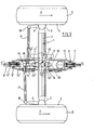
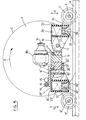
- FIGS. 1 to 3 represent a directional axle, generally designated by the reference notation 1 and comprising a body 2 provided at each of its ends with spindles of axis 3 of wheels 4 with pneumatic tires 5 to which are levers of steering 6.
- a unidirectional automatic guidance system according to the invention comprising a roller 7 intended to be engaged in a rail 8 extending in the longitudinal axis UU 'of the running track of a vehicle not shown.
- This roller 7 is mounted on a shaft 9 carried by a support arm 10 extending in the direction of movement of the vehicle indicated by the arrows Z relative to the directional axle 1.
- the support arm 10 can oscillate vertically according to the arrows V around a substantially horizontal pivot 11 carried by a turret designated as a whole by the reference notation 12, mounted on a pivot 13 fixed on the body 2 of the directional axle 1.
- This pivot 13 which can be carried by the vehicle rather than by the axle 1, extends in a substantially vertical or oblique direction below the body 2 of the axle.
- the pivot 11 of the arm 10 is in fact carried by a first extension 14 of the turret 12, which may have a cross section in the shape of an inverted U and is integral with this turret 12.
- the turret 12 In the opposite direction to the direction of movement of the vehicle, the turret 12 has a second extension 14 'carrying ball joints 15, 16 which connect it to coupling bars 17 articulated at 18 to the steering lever 6 of each wheel 5.
- a cross 19 ' is subject to the second extension 14' of the turret 12 by a substantially vertical pivot 20 '.
- a second support arm 10 ' At the cross 19 'is suspended by a substantially horizontal pivot 11' a second support arm 10 'extending in the opposite direction to that of the movement of the vehicle, this support arm 10' carrying the shaft 9 'of a second 7 'roller.
- This support arm 10 'can thus oscillate vertically around the substantially horizontal pivot 11' in the same way as the support arm 10.
- the support arm 10 'can also pivot horizontally, independently of the turret 12 around the substantially vertical pivot 20 t of 19 'spider.
- the cross 19 ' has a lower appendage 21' limiting the horizontal pivoting of this cross 19 'and the support arm 10' to a predetermined extent, between stops 22 'carried by the turret 12 on either side of the lower appendage 21 'of the cross 19'.
- the support arms 10, 10' of the rollers 7, 7 ' are suspended respectively from the extensions 14 and 27' of the turret 12 respectively of the cross 19 'by a suspension system, preferably a double suspension system comprising two distinct suspension elements constituted, in the embodiment shown, by helical springs 23, 23 'and pneumatic devices 24, 24'.
- the helical spring 23 bears, on the one hand, on the first extension 14 of the turret 12 and, on the other hand, on a base 25 supported by a hinge device 26, such as a substantially horizontal pivot or a ball joint, carried by the support arm 10, while the pneumatic device 24 also bears on the first extension 14 of the turret 12 and on the base 25 supported by the articulation device 26 carried by the support arm 10 of the roller 7.
- the helical spring 23 ' As for the helical spring 23 ', it is supported, on the one hand, on an extension 27' of the cross 19 ', carried by the extension 14' and, on the other hand on a base 25 'supported by a hinge device 26 'such as a substantially horizontal pivot or a ball joint, carried by the support arm 10' of the roller 7 ', while the pneumatic device 24' also bears on the extension 27 'of the cross 19' and, via of the base 25 ', on the articulation device 26' carried by the support arm 10 'of the roller 7'.
- a hinge device 26 ' such as a substantially horizontal pivot or a ball joint
- the coil spring 23 and the pneumatic device 24, as well as the coil spring 23 'and the pneumatic device 24' are coaxial. These suspension systems are intended to ensure adequate guidance and contact of the rollers 7, 7 'on the rail 8.
- the pressure of the pneumatic devices 24, 24' is adjusted, so that the pressure and the limit value of transverse retention of the rollers 7, 7 'on the rail 8 are kept substantially proportional to the total weight (tare + payload) applied to each axle of the vehicle.
- each roller 7, 7 ' has a core 28 inserted between two beads 29, 30.
- a groove 31 intended to receive a projection 32 of rail 8 when the vehicle is traveling on its own site.
- the core 28 of the rollers 7, 7 ' has, on either side of the groove 31, a tread 33, 34 whose role will be explained below.
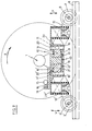
- the guide system partially shown in Figures 1 and 3 comprises means for lifting the support arms, for example the arm 10 '.
- These lifting means comprise a double-acting lifting cylinder 35, comprising a cylinder 36 mounted on the pivot 11 'of the support arm 10' and a piston 37, articulated at 38, at one end of a lever 39, the l 'opposite end is articulated by means of a shaft 40 to the extension 27' of the cross 19 ', as well as on each side of the support arm 10', a cable 41, one end of which is attached to the support arm 10 ' and the other is attached to the lever 39, on one side of the support arm 10 ', and to a crank 42 secured to the lever 39 by the shaft 40, on the other side of the support arm 10'.
- a double-acting lifting cylinder 35 comprising a cylinder 36 mounted on the pivot 11 'of the support arm 10' and a piston 37, articulated at 38, at one end of a lever 39, the l 'opposite end is
- the support arm 10 'of the roller 7' can be raised by actuating the jack 35, the piston 37 of which pivots the lever 39 and the crank 42 in the sinistrorsum direction (FIG. 3), so as to tension the cables 41, which are bent in the relaxed position, and thus raise the roller 7 'and its support arm 10'.
- each support arm for example of the arm 10 ′
- the arrangement of the lifting elements of each support arm is such that in the raised position, these elements occupy a stable position, even if a loss of hydraulic pressure occurs in the lifting cylinder 35 This stability is ensured by the tilting of the lever 39 and of the crank 42 beyond the position tending to cause them to return in the dextrorsum direction (FIG. 3).
- the front roller 7 corrects any deviations in the trajectory of the directional axle 1 relative to the guide rail 8 and transmits them by a rotation movement to the arm support 10 which drives the turret 12.
- the turret 12 communicates its orientation, taking into account the value of drift of the pneumatic tires 5, to the steering levers 6 which correct the deflection of the wheels 4 carried by the axle.
- the distance between the pivot 13 on which the turret 12 is mounted and the ball joints 15, 16 by which this turret 12 is connected to the coupling bars 17 is such that the turret 12 oscillates by an angle less than that of the average of the steering of the wheels 4 carried by the axle 1.
- the support arm 10 ′ with freedom of horizontal pivoting collides with the stops 22 only in the event of abnormal drift or slippage of said axle 1.
- the two rollers 7, 7 ′ then have the task of retaining the axle 1 transversely with respect to to its intended path and to prevent further lateral sliding of the vehicle.
- a slight inclination of the pivot 20 'of the cross 19' relative to the vertical plane is intended to slightly incline the roller 7 'on the rail 8 so as to compensate for any transverse cant effect of the axle 1. This inclination of the roller 7' ensures optimum attachment of this roller 7 'to the rail 8.
- each roller 7, 7 ′ has a core 28 inserted between two possibly conical beads 29, 30, this core being, for example of substantially cylindrical to slightly bitronconic, especially in diabolo.
- peripheral groove 31 is intended to engage the complementary projection 32 extending along the sections of the rail 8 where the vehicle is intended to travel on its own site.
- This projection 32 of the rail 8 and the groove 31 of the core 28 of the rollers 7, 7 ' provide additional guiding security to that already provided by the rail 8 and the beads 29 and 30 of the rollers 7, 7'.
- This projection 32 also has the advantage of eliminating practically any risk of derailment of the rollers 7, 7 'since it cannot be obstructed by any object deposited on the track.
- the rollers 7, 7 ′ are intended to ensure the return of the electric current captured for example by a pantograph on a single wire. The return of the current is thus ensured by rolling and not by friction, any problem of pad wear being thus avoided.
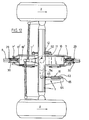
- Figures 5 to 7 show a directional axle 1 on which is mounted a bidirectional automatic guidance system.
- This includes, like the unidirectional guide system, rollers 7, 7 ', intended to be engaged in a rail 8.
- rollers 7, 7' are mounted on shafts 9, 9 'carried by support arms 10, 10 '.
- the bidirectional system differs from the unidirectional system illustrated in FIGS. 1 to 3, however, in that the support arms 10, 10 ′ are secured to the turret 12 so that they can both oscillate vertically and pivot horizontally independently of the turret 12 to a predetermined extent.
- the turret 12 has on each side corresponding to the possible opposite directions of movement of the vehicle, extensions 14, 14 '.
- These extensions 14, 14 ′ are secured by substantially vertical pivots 20, 20 ′ of the braces 19, 19 ′ to which the support arms 10, 10 'are suspended by substantially horizontal pivots 11, 11'.
- These support arms 10, 10 ′ extend in the two possible directions of movement of the vehicle. They can oscillate vertically along the arrows V around the substantially horizontal pivots 11, 11 '.
- the horizontal pivoting of the braces 19, 19 'and of the support arms 10, 10' is limited by lower appendages 21, 21 'which have the braces 19, 19' between the stops 22, 22 'carried by the turret 12.
- FIGS. 5 to 7 the suspension of the support arms 10, 10 ′ is carried out in the same manner as in the embodiment of the unidirectional system shown in FIGS. 1 to 3. The same is true of the lifting means and their layout.
- One of the extensions 14, 14 ' for example the extension 14', carries ball joints 15, 16 which connect it to the coupling bars 17 articulated at 18 to the steering lever 6 of each wheel 4.
- the distance between the pivot 13 on which the turret 12 is mounted and the ball joints 15, 16 is such that this turret 12 oscillates at an angle less than that of the average turning of the two wheels 4 carried by the axle 1.
- a device for reversing the direction of travel comprising a lever for reversing the direction of travel 44 oscillating at one end on a journal 45 carried by the turret 12 and provided on each side with a boss 46, 46 'capable of engaging in a housing 47, 47' formed in an extension 48, 48 ', possibly coincident with the lower appendages 21, 21 t , of the cross 19, 19'.
- the reversing lever 44 is actuated by a hydromechanical rack and pinion device, which is generally designated by the reference numeral 49 and which comprises a pinion 50 fixed to one end of a crank 51, the other end of which carries a spindle 52 guided in a fork 53 formed at the end of the lever 44, opposite the end carrying the pin 45 of this lever 44.
- a hydromechanical rack and pinion device which is generally designated by the reference numeral 49 and which comprises a pinion 50 fixed to one end of a crank 51, the other end of which carries a spindle 52 guided in a fork 53 formed at the end of the lever 44, opposite the end carrying the pin 45 of this lever 44.
- the direction of travel of the vehicle is selected by the reversing device 43. This secures, for example; for the direction of travel Z, the front support arm 10 of the turret 12, but nevertheless allows a certain freedom of horizontal pivoting of the rear support arm 10 '.
- the unidirectional version is preferred on a two-axle vehicle having automatic guidance only on the front axle
- the bidirectional version is preferred on rigid two-axle vehicles and articulated vehicles with at least three axles , equipped with automatic guidance on each axle.
- the turret 12 comprises a steering arm 54 intended to be controlled by a guide device different from the rail 8, shown diagrammatically at 55.
- This guide device 55 other than by rail is intended to allow the vehicle to move autonomously after lifting the rollers 7, 7 '.
- one of the steering levers 6 of the wheels 4 has an extension 56 intended to be controlled by a different guide device 57 rail 8.
- This device 57 allows the vehicle to travel autonomously after lifting the rollers 7,7 '.
- FIG. 10 schematically shows a guide device 55 other than by rail 8 intended to be associated with the steering arm 54.
- the latter is mounted on a vertical pivot 58 concentric with the pivot 13 around which the turret 12 can pivot, a device for clutch 59 being associated with the steering arm 54 for securing for guidance other than the rail 8 or detaching for automatic guidance this arm 54 of the turret 12.
- FIG. 11 which shows a device for detaching the automatic guidance system for driving, for example manual
- the extension 14 ′ of the turret 12 carrying the ball joints 15, 16 is supported, at one end, by a concentric vertical pivot 60 to the pivot 13 carrying the turret 12 and can be separated, for a different guidance from the rail 8, or be secured, for an automatic guidance of the turret 12 or the vertical pivot 20 or 20 ', by a device clutch 59 associated with the extension 14 '.
- FIG. 12 A variant of the unidirectional or bidirectional automatic guidance system of FIGS. 1 to 3 and 5 to 7 for selecting the path to follow in a static diverging switch is shown in FIG. 12.
- This variant comprises in addition to the unidirectional guide system shown in Figures 1 to 3 or bidirectional guide shown in Figures 5 to 7, two double-acting cylinders 61, 62.
- the first cylinder 61 acts on the steering arm 54 of the turret 12 so as to press against the rail 8, one of the beads 29, 30 of the roller 7 carried by the support arm 10 extending in the direction of movement of the vehicle.
- This first cylinder comprises a cylinder 63 articulated to a support 64, an axis 65 fixed to the axle 1 and a piston 66 articulated to the steering arm 54 of the turret 12.
- the second double-acting cylinder 62 which is intended to orient the cross 19 'carrying the support arm 10' of the other roller 7 ', oriented in the opposite direction to that indicated by the arrow Z, connects the horizontal pivots 11, 11 1 carrying the support arms 10, 10' of the rollers 7, 7 '.
- These jacks 61 and 62 act so as to press against the rail 8, the beads 29, 30 of each roller 7, 7 '; these beads being located on the same side of the rail 8.
- the rollers 7, 7 ′ select the face of the guide rail 8 to be followed and therefore the branch to be followed in a diverging static switch.
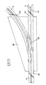
- FIG. 13 shows such a left splitting switch composed of sections 67 of a rail similar to that shown in FIG. 4.
- This switch consists of a frame 68 on which are fixed the rail sections 67 whose ends adjacent to a splitting zone 69 are profiled so as to allow the beads 29, 30 of each roller 7, 7 'to pass through the switch.
- the projection 32 of the rail 8 intended to engage in the groove of each roller 7, 7 ' is interrupted so as not to hinder the crossing of the switch.
- the tires with pneumatic tires of the directional axle equipped with a guidance system according to the invention can be driven.
- a differential 70 connected to a drive shaft 71 , transmits the engine force to a wheel shaft 7 2 , connected to the drive wheel 4, by means of a universal joint 73.
- the system can include arms that can oscillate vertically thanks to their flexibility in the vertical plane.
- Such arms are for example made up of leaf springs 74 and fixed to the turret 12 by bolts 75, as shown in FIG. 16.
- the guidance system according to the invention can equip not only the front axle of a rigid vehicle, but also the rear axle of this vehicle. It can also independently equip several or all of the axles of an articulated vehicle, regardless of whether these axles are mounted on a ball circle or that they have wheel axle rockets.
Landscapes
- Engineering & Computer Science (AREA)
- Chemical & Material Sciences (AREA)
- Combustion & Propulsion (AREA)
- Transportation (AREA)
- Mechanical Engineering (AREA)
- Platform Screen Doors And Railroad Systems (AREA)
- Automobile Manufacture Line, Endless Track Vehicle, Trailer (AREA)
- Guiding Agricultural Machines (AREA)
- Steering Controls (AREA)
Priority Applications (1)
| Application Number | Priority Date | Filing Date | Title |
|---|---|---|---|
| AT82200356T ATE13503T1 (de) | 1981-04-02 | 1982-03-24 | Automatisches fuehrungssystem fuer ein mit reifen ausgeruestetes fahrzeug. |
Applications Claiming Priority (2)
| Application Number | Priority Date | Filing Date | Title |
|---|---|---|---|
| LU83276A LU83276A1 (fr) | 1981-04-02 | 1981-04-02 | Systeme de guidage automatique d'un vehicule muni de roues a bandage pneumatique |
| LU83276 | 1981-04-02 |
Publications (2)
| Publication Number | Publication Date |
|---|---|
| EP0062370A1 true EP0062370A1 (de) | 1982-10-13 |
| EP0062370B1 EP0062370B1 (de) | 1985-05-29 |
Family
ID=19729621
Family Applications (1)
| Application Number | Title | Priority Date | Filing Date |
|---|---|---|---|
| EP82200356A Expired EP0062370B1 (de) | 1981-04-02 | 1982-03-24 | Automatisches Führungssystem für ein mit Reifen ausgerüstetes Fahrzeug |
Country Status (6)
| Country | Link |
|---|---|
| US (1) | US4454819A (de) |
| EP (1) | EP0062370B1 (de) |
| AT (1) | ATE13503T1 (de) |
| CA (1) | CA1177695A (de) |
| DE (1) | DE3263858D1 (de) |
| LU (1) | LU83276A1 (de) |
Cited By (7)
| Publication number | Priority date | Publication date | Assignee | Title |
|---|---|---|---|---|
| WO1988000544A1 (fr) * | 1986-07-17 | 1988-01-28 | S.A. Constructions Ferroviaires Et Metalliques | Systeme d'autoguidage d'un vehicule rapide equipe de roues directrices a bandage pneumatique |
| EP0583199A1 (de) * | 1992-08-11 | 1994-02-16 | Techlam | Einstellvorrichtung für ein Reifenfahrzeug-Drehgestell |
| FR2708245A1 (fr) * | 1993-07-27 | 1995-02-03 | Cogifer | Système de guidage automatique de véhicule automoteur de type routier. |
| FR2715119A1 (fr) * | 1994-01-20 | 1995-07-21 | Lohr Ind | Bras perfectionné d'autoguidage d'un véhicule routier le long d'un rail directeur. |
| FR2755982A1 (fr) * | 1996-11-20 | 1998-05-22 | Spie Enertrans | Appareil de changement de trajectoire d'un vehicule guide, et installation comprenant un tel appareil |
| US5758583A (en) * | 1993-05-26 | 1998-06-02 | Lohr Industrie, S.A. | Unit for directionally guiding a transport vehicle along a rail |
| EP1099613A1 (de) * | 1999-11-09 | 2001-05-16 | Gehwolf, Friedrich | Selbstfahrender Wagen und System mit derartigem selbstfahrenden Wagen |
Families Citing this family (11)
| Publication number | Priority date | Publication date | Assignee | Title |
|---|---|---|---|---|
| US4926958A (en) * | 1987-06-04 | 1990-05-22 | Toyota Jidosha Kabushiki Kaisha | Guide device for automated guided vehicle |
| DE4100294C1 (de) * | 1991-01-08 | 1992-03-12 | Mercedes-Benz Aktiengesellschaft, 7000 Stuttgart, De | |
| BE1008920A4 (fr) * | 1994-11-28 | 1996-10-01 | Bombardier Eurorail Sa | Systeme de guidage a rail et galet a gorge. |
| US6308640B1 (en) * | 1999-03-12 | 2001-10-30 | Daimlerchrysler Ag | Transportation vehicle steering apparatus |
| US8161889B2 (en) * | 2006-11-16 | 2012-04-24 | Mitsubishi Heavy Industries, Ltd. | Bogie structure for a track vehicle |
| JP5107280B2 (ja) * | 2009-02-26 | 2012-12-26 | 三菱重工業株式会社 | 軌道系車両用台車 |
| JP4995216B2 (ja) * | 2009-03-25 | 2012-08-08 | 三菱重工業株式会社 | 軌道系車両用台車 |
| JP4995217B2 (ja) | 2009-03-25 | 2012-08-08 | 三菱重工業株式会社 | 軌道系車両用台車及び軌道系車両 |
| CA2668966C (en) * | 2009-06-26 | 2011-09-13 | Lanza Projects Corporation | Railway truck |
| CN115257913B (zh) * | 2022-06-16 | 2023-06-23 | 中车唐山机车车辆有限公司 | 一种无轨电车迫导向系统及无轨电车 |
| US12485958B2 (en) | 2023-09-19 | 2025-12-02 | Torc Robotics, Inc. | Feedback control system and steering gear box for final steering control of an autonomous vehicle |
Citations (4)
| Publication number | Priority date | Publication date | Assignee | Title |
|---|---|---|---|---|
| DE221586C (de) * | ||||
| FR1131357A (fr) * | 1954-10-08 | 1957-02-20 | Azienda Tranviaria Municipale | Dispositif de guidage escamotable pour véhicules automobiles destinés à circuler indifférement sur route ordinaire et sur rail de guidage |
| FR1131358A (fr) * | 1954-10-08 | 1957-02-20 | Azienda Tranviaria Municipale | Bogie à deux essieux pour véhicules destinés à circuler sur rail |
| FR2307693A1 (fr) * | 1975-04-14 | 1976-11-12 | Matra Engins | Vehicule de transport notamment destine a une voie banalisee |
Family Cites Families (3)
| Publication number | Priority date | Publication date | Assignee | Title |
|---|---|---|---|---|
| US2468158A (en) * | 1945-08-27 | 1949-04-26 | Orlo A Bartholomew | Automatic steering mechanism for trolley coaches and the like |
| BE547674A (de) * | 1955-05-12 | Michelin & Cie | ||
| DK113124A (de) * | 1964-03-25 |
-
1981
- 1981-04-02 LU LU83276A patent/LU83276A1/fr unknown
-
1982
- 1982-03-24 DE DE8282200356T patent/DE3263858D1/de not_active Expired
- 1982-03-24 EP EP82200356A patent/EP0062370B1/de not_active Expired
- 1982-03-24 AT AT82200356T patent/ATE13503T1/de not_active IP Right Cessation
- 1982-03-30 US US06/363,735 patent/US4454819A/en not_active Expired - Lifetime
- 1982-03-30 CA CA000399838A patent/CA1177695A/fr not_active Expired
Patent Citations (4)
| Publication number | Priority date | Publication date | Assignee | Title |
|---|---|---|---|---|
| DE221586C (de) * | ||||
| FR1131357A (fr) * | 1954-10-08 | 1957-02-20 | Azienda Tranviaria Municipale | Dispositif de guidage escamotable pour véhicules automobiles destinés à circuler indifférement sur route ordinaire et sur rail de guidage |
| FR1131358A (fr) * | 1954-10-08 | 1957-02-20 | Azienda Tranviaria Municipale | Bogie à deux essieux pour véhicules destinés à circuler sur rail |
| FR2307693A1 (fr) * | 1975-04-14 | 1976-11-12 | Matra Engins | Vehicule de transport notamment destine a une voie banalisee |
Cited By (13)
| Publication number | Priority date | Publication date | Assignee | Title |
|---|---|---|---|---|
| WO1988000544A1 (fr) * | 1986-07-17 | 1988-01-28 | S.A. Constructions Ferroviaires Et Metalliques | Systeme d'autoguidage d'un vehicule rapide equipe de roues directrices a bandage pneumatique |
| EP0583199A1 (de) * | 1992-08-11 | 1994-02-16 | Techlam | Einstellvorrichtung für ein Reifenfahrzeug-Drehgestell |
| FR2694734A1 (fr) * | 1992-08-11 | 1994-02-18 | Techlam | Dispositif orienteur pour bogie de véhicule équipé de roues à pneumatiques. |
| US5410969A (en) * | 1992-08-11 | 1995-05-02 | Techlam | Steering device for a vehicle bogey fitted with wheels having pneumatic tires |
| US5758583A (en) * | 1993-05-26 | 1998-06-02 | Lohr Industrie, S.A. | Unit for directionally guiding a transport vehicle along a rail |
| FR2708245A1 (fr) * | 1993-07-27 | 1995-02-03 | Cogifer | Système de guidage automatique de véhicule automoteur de type routier. |
| WO1995019904A1 (fr) * | 1994-01-20 | 1995-07-27 | Lohr Industrie | Bras perfectionne d'autoguidage d'un vehicule routier le long d'un rail directeur |
| US5704295A (en) * | 1994-01-20 | 1998-01-06 | Lohr Industrie | Arm for automatically guiding a road vehicle along a guide rail |
| FR2715119A1 (fr) * | 1994-01-20 | 1995-07-21 | Lohr Ind | Bras perfectionné d'autoguidage d'un véhicule routier le long d'un rail directeur. |
| CN1048217C (zh) * | 1994-01-20 | 2000-01-12 | 罗尔工业公司 | 一种沿导轨自动导引公路车辆的改进的导臂 |
| FR2755982A1 (fr) * | 1996-11-20 | 1998-05-22 | Spie Enertrans | Appareil de changement de trajectoire d'un vehicule guide, et installation comprenant un tel appareil |
| EP0844329A1 (de) * | 1996-11-20 | 1998-05-27 | Spie Enertrans | Vorrichtung zum Ändern des Weges eines geführten Fahrzeugs und Einrichtung enthaltend eine derartige Vorrichtung |
| EP1099613A1 (de) * | 1999-11-09 | 2001-05-16 | Gehwolf, Friedrich | Selbstfahrender Wagen und System mit derartigem selbstfahrenden Wagen |
Also Published As
| Publication number | Publication date |
|---|---|
| DE3263858D1 (en) | 1985-07-04 |
| EP0062370B1 (de) | 1985-05-29 |
| ATE13503T1 (de) | 1985-06-15 |
| US4454819A (en) | 1984-06-19 |
| CA1177695A (fr) | 1984-11-13 |
| LU83276A1 (fr) | 1983-03-24 |
Similar Documents
| Publication | Publication Date | Title |
|---|---|---|
| EP0062370B1 (de) | Automatisches Führungssystem für ein mit Reifen ausgerüstetes Fahrzeug | |
| EP2531157B1 (de) | Vorrichtung zur ermöglichung der überwindung von hindernissen mit einem rollstuhl | |
| EP0739286B1 (de) | Selbstlenkungsarm eines strassenfahrzeugs entlang einer leitschiene | |
| EP0960045B1 (de) | Führungssystem entlang mindestens einer bodenschiene für eine achse eines strassenfahrzeugs | |
| EP0026147B1 (de) | Automatische Eindrahtungsvorrichtung eines elektrischen Fahrzeugs vom Typ des Oberleitungsbusses | |
| EP0518750B1 (de) | Spezialwagen zum Einsammeln oder Verteilen von Eisenbahn-Drehgestellen oder dergleichen für den Schienentransport von Strassenschwerlastfahrzeugen | |
| FR2630683A1 (fr) | Vehicule pour deplacer des vehicules sur rails | |
| CA2670672C (fr) | Sabot de calage d'une roue et installation de calage motorisee | |
| EP1073576B1 (de) | Seitlichen versatz erlaubende, bidirektionale leitschienenführungs- einrichtung für eine strassenachse | |
| EP0291491B1 (de) | Lenk- und Tragevorrichtung für ein Eisenbahnfahrzeug | |
| FR2539124A3 (fr) | Dispositif de levage et de basculement pour l'entretien et la reparation de vehicules | |
| FR2478046A1 (fr) | Installation de manutention | |
| EP0648660B1 (de) | Vorrichtung und Verfahren zum Antrieb und Bewegen von Schienen- oder Strassenfahrzeugen | |
| FR2623459A1 (fr) | Dispositif de guidage et de changement de voie pour vehicule guide par un rail | |
| FR2582593A1 (fr) | Dispositif pour le blocage de la suspension d'un vehicule notamment en vue d'ameliorer sa stabilite transversale | |
| FR2545763A1 (fr) | Perfectionnement aux vehicules susceptibles de circuler soit sur route, soit sur voie ferree | |
| EP0114134B1 (de) | Fahrzeug mit Hebebühne, insbesondere für Körperbehinderte | |
| EP1381524A1 (de) | Vorrichtung zur verbesserung der manövrierfähigkeit eines transportwagens | |
| FR2544700A1 (fr) | Rampe de chargement deplacable comme une remorque routiere | |
| FR2512411A1 (fr) | Remorque | |
| FR2863237A1 (fr) | Vehicule d'intervention sur des equipements ferroviaires et procede de positionnement sur des rails de ce vehicule | |
| FR2585295A1 (fr) | Vehicule remorquable comprenant un dispositif d'attelage extensible | |
| EP0725020A1 (de) | Abnehmbares Werk zur Richtstrahlbeförderung einer Schwerlast | |
| CH373271A (fr) | Dispositif pour déplacer transversalement un véhicule automobile | |
| FR2623485A1 (fr) | Appareil de manutention destine a hisser des charges telles que par exemple des echelles sur le toit d'un vehicule |
Legal Events
| Date | Code | Title | Description |
|---|---|---|---|
| PUAI | Public reference made under article 153(3) epc to a published international application that has entered the european phase |
Free format text: ORIGINAL CODE: 0009012 |
|
| AK | Designated contracting states |
Designated state(s): AT BE CH DE FR GB IT NL SE |
|
| 17P | Request for examination filed |
Effective date: 19830221 |
|
| ITF | It: translation for a ep patent filed | ||
| GRAA | (expected) grant |
Free format text: ORIGINAL CODE: 0009210 |
|
| AK | Designated contracting states |
Designated state(s): AT BE CH DE FR GB IT LI NL SE |
|
| REF | Corresponds to: |
Ref document number: 13503 Country of ref document: AT Date of ref document: 19850615 Kind code of ref document: T |
|
| REF | Corresponds to: |
Ref document number: 3263858 Country of ref document: DE Date of ref document: 19850704 |
|
| PLBE | No opposition filed within time limit |
Free format text: ORIGINAL CODE: 0009261 |
|
| STAA | Information on the status of an ep patent application or granted ep patent |
Free format text: STATUS: NO OPPOSITION FILED WITHIN TIME LIMIT |
|
| 26N | No opposition filed | ||
| ITTA | It: last paid annual fee | ||
| EAL | Se: european patent in force in sweden |
Ref document number: 82200356.2 |
|
| PGFP | Annual fee paid to national office [announced via postgrant information from national office to epo] |
Ref country code: BE Payment date: 20010122 Year of fee payment: 20 |
|
| PGFP | Annual fee paid to national office [announced via postgrant information from national office to epo] |
Ref country code: SE Payment date: 20010222 Year of fee payment: 20 |
|
| PGFP | Annual fee paid to national office [announced via postgrant information from national office to epo] |
Ref country code: GB Payment date: 20010226 Year of fee payment: 20 Ref country code: CH Payment date: 20010226 Year of fee payment: 20 Ref country code: AT Payment date: 20010226 Year of fee payment: 20 |
|
| PGFP | Annual fee paid to national office [announced via postgrant information from national office to epo] |
Ref country code: NL Payment date: 20010307 Year of fee payment: 20 |
|
| PGFP | Annual fee paid to national office [announced via postgrant information from national office to epo] |
Ref country code: DE Payment date: 20010308 Year of fee payment: 20 |
|
| PGFP | Annual fee paid to national office [announced via postgrant information from national office to epo] |
Ref country code: FR Payment date: 20010330 Year of fee payment: 20 |
|
| BE20 | Be: patent expired |
Free format text: 20020324 *S.A. CONSTRUCTIONS FERROVIAIRES ET METALLIQUES |
|
| REG | Reference to a national code |
Ref country code: GB Ref legal event code: IF02 |
|
| PG25 | Lapsed in a contracting state [announced via postgrant information from national office to epo] |
Ref country code: LI Free format text: LAPSE BECAUSE OF EXPIRATION OF PROTECTION Effective date: 20020323 Ref country code: GB Free format text: LAPSE BECAUSE OF EXPIRATION OF PROTECTION Effective date: 20020323 Ref country code: CH Free format text: LAPSE BECAUSE OF EXPIRATION OF PROTECTION Effective date: 20020323 |
|
| PG25 | Lapsed in a contracting state [announced via postgrant information from national office to epo] |
Ref country code: NL Free format text: LAPSE BECAUSE OF EXPIRATION OF PROTECTION Effective date: 20020324 Ref country code: AT Free format text: LAPSE BECAUSE OF EXPIRATION OF PROTECTION Effective date: 20020324 |
|
| REG | Reference to a national code |
Ref country code: CH Ref legal event code: PL |
|
| REG | Reference to a national code |
Ref country code: GB Ref legal event code: PE20 Effective date: 20020323 |
|
| EUG | Se: european patent has lapsed |
Ref document number: 82200356.2 |
|
| NLV7 | Nl: ceased due to reaching the maximum lifetime of a patent |
Effective date: 20020324 |
|
| NLV7 | Nl: ceased due to reaching the maximum lifetime of a patent |
Effective date: 20020324 |