EP0062398B1 - Verfahren zum Entfernen von Flüssigkeiten aus Mischgefässen - Google Patents
Verfahren zum Entfernen von Flüssigkeiten aus Mischgefässen Download PDFInfo
- Publication number
- EP0062398B1 EP0062398B1 EP82300701A EP82300701A EP0062398B1 EP 0062398 B1 EP0062398 B1 EP 0062398B1 EP 82300701 A EP82300701 A EP 82300701A EP 82300701 A EP82300701 A EP 82300701A EP 0062398 B1 EP0062398 B1 EP 0062398B1
- Authority
- EP
- European Patent Office
- Prior art keywords
- discharge
- port
- mixing
- discharge port
- metal
- Prior art date
- Legal status (The legal status is an assumption and is not a legal conclusion. Google has not performed a legal analysis and makes no representation as to the accuracy of the status listed.)
- Expired
Links
- 239000007788 liquid Substances 0.000 title claims description 16
- 238000000034 method Methods 0.000 title claims description 9
- 239000002184 metal Substances 0.000 claims description 37
- 229910052751 metal Inorganic materials 0.000 claims description 37
- 239000007787 solid Substances 0.000 claims description 7
- 238000007599 discharging Methods 0.000 claims description 6
- 239000002245 particle Substances 0.000 claims description 3
- 238000005266 casting Methods 0.000 description 3
- 239000000203 mixture Substances 0.000 description 3
- 230000000694 effects Effects 0.000 description 2
- 238000002844 melting Methods 0.000 description 2
- 230000008018 melting Effects 0.000 description 2
- 150000002739 metals Chemical class 0.000 description 2
- 238000007789 sealing Methods 0.000 description 2
- 238000003756 stirring Methods 0.000 description 2
- OKTJSMMVPCPJKN-UHFFFAOYSA-N Carbon Chemical compound [C] OKTJSMMVPCPJKN-UHFFFAOYSA-N 0.000 description 1
- 229910001018 Cast iron Inorganic materials 0.000 description 1
- 230000002411 adverse Effects 0.000 description 1
- 229910045601 alloy Inorganic materials 0.000 description 1
- 239000000956 alloy Substances 0.000 description 1
- 239000000919 ceramic Substances 0.000 description 1
- 229910010293 ceramic material Inorganic materials 0.000 description 1
- 238000004140 cleaning Methods 0.000 description 1
- 239000012530 fluid Substances 0.000 description 1
- 229910002804 graphite Inorganic materials 0.000 description 1
- 239000010439 graphite Substances 0.000 description 1
- 238000010438 heat treatment Methods 0.000 description 1
- 239000003779 heat-resistant material Substances 0.000 description 1
- 239000000463 material Substances 0.000 description 1
- 229910001092 metal group alloy Inorganic materials 0.000 description 1
- 238000007711 solidification Methods 0.000 description 1
- 230000008023 solidification Effects 0.000 description 1
- 238000011144 upstream manufacturing Methods 0.000 description 1
Images
Classifications
-
- C—CHEMISTRY; METALLURGY
- C22—METALLURGY; FERROUS OR NON-FERROUS ALLOYS; TREATMENT OF ALLOYS OR NON-FERROUS METALS
- C22B—PRODUCTION AND REFINING OF METALS; PRETREATMENT OF RAW MATERIALS
- C22B9/00—General processes of refining or remelting of metals; Apparatus for electroslag or arc remelting of metals
- C22B9/02—Refining by liquating, filtering, centrifuging, distilling, or supersonic wave action including acoustic waves
-
- C—CHEMISTRY; METALLURGY
- C22—METALLURGY; FERROUS OR NON-FERROUS ALLOYS; TREATMENT OF ALLOYS OR NON-FERROUS METALS
- C22C—ALLOYS
- C22C1/00—Making non-ferrous alloys
- C22C1/12—Making non-ferrous alloys by processing in a semi-solid state, e.g. holding the alloy in the solid-liquid phase
-
- Y—GENERAL TAGGING OF NEW TECHNOLOGICAL DEVELOPMENTS; GENERAL TAGGING OF CROSS-SECTIONAL TECHNOLOGIES SPANNING OVER SEVERAL SECTIONS OF THE IPC; TECHNICAL SUBJECTS COVERED BY FORMER USPC CROSS-REFERENCE ART COLLECTIONS [XRACs] AND DIGESTS
- Y02—TECHNOLOGIES OR APPLICATIONS FOR MITIGATION OR ADAPTATION AGAINST CLIMATE CHANGE
- Y02P—CLIMATE CHANGE MITIGATION TECHNOLOGIES IN THE PRODUCTION OR PROCESSING OF GOODS
- Y02P10/00—Technologies related to metal processing
- Y02P10/20—Recycling
Definitions
- This invention relates to an improved method of discharging liquids from a mixing chamber and is particularly suited to the discharge of molten metals such as those metals and alloys which contain discrete degenerate dendritic primary solid particles and are to be subjected to casting techniques.
- US-A-3,954,455 and 3,936,298 describe metal and metal alloy compositions which contain discrete degenerate dendritic primary solid particles and disclose the advantages of using such materials in casting; e.g., lower temperatures, longer mould life, etc.
- US-A-4,194,552 which discloses the features of the precharacterising parts of claims 1 and 4, is of interest with respect to a mixing apparatus for such metal compositions. In carrying out such casting methods it is necessary that the metal be thoroughly mixed while it is held in the mixing chambers so that, when cast, the metal is uniform in composition throughout. Also, it is important that the metal remain uniformly semi-solid throughout the mixing chamber and not solidify.
- the present invention provides a process for mixing and discharging a liquid from a mixing chamber wherein the liquid is agitated by a vertically disposed agitating member, there being provided, in combination, a discharge port centrally disposed at the bottom of said mixing chamber, and seating means at the bottom of said agitating member adapted to fit into the upper portion of said port, the discharge and termination of discharge of liquid being accomplished by raising said agitating member, whereby liquid flows through said port, and, when termination of liquid flow is desired, lowering said rotating agitating member to seat said seating means in the upper portion of said port white maintaining rotation thereof, characterised in that there is provided a stopper plug which seats into the bottom portion of the discharge port, whereby discharge of liquid is effected by removing the stopper plug from the discharge port when the agitating member is in the raised position, the stopper plug being removed in a vertical and then in a horizontal path, and, in termination of discharge, after lowering the rotating agitating member the bottom portion of the discharge port is closed by replacing the stopper plug,
- the invention also provides a mixing chamber for mixing and discharging molten metal wherein said metal is agitated by a vertically disposed mixing member, comprising in combination, a discharge port centrally disposed at the bottom of said mixing chamber, and seating means at the bottom of said mixing chamber adapted to fit into the upper portion of said port, whereby the discharge and termination of discharge of molten metal can be accomplished by raising said mixing member, whereby metal flows through said port, and, when termination of metal flow is desired, lowering said rotating mixing member to seat said seating means in the upper portion of said port while maintaining rotation thereof, characterised by a stopper plug adapted to seat into the bottom portion of the discharge port, and means for removing the stopper plug from the discharge port in a vertical path and then in a horizontal path, whereby discharge of molten metal is effected by removing the stopper plug from the discharge port when the mixing member is in the raised position, and, in termination of discharge, after lowering the rotating mixing member, the bottom of said port is closed by replacing said stopper plug, after which the
- the present invention provides a novel mixing chamber and method of use wherein a liquid such as molten metal is uniformly mixed without solidification occurring.
- a liquid such as molten metal is uniformly mixed without solidification occurring.
- the molten metal from the mixing chamber flows smoothly and, when desired, flow may be smoothly stopped without splattering.
- the closure means of the flow port does not wear in a manner to adversely effect the system.
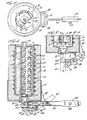
- the stirring device shown generally as 11 is within a ceramic insulated chamber 13 seated in a lower housing retaining member 15 and heated electrically by heating coils 17.
- the fluid metal 21 is agitated by the stirrer 11 which is turned by a motor (not shown) attached to a driving shaft 23 at the upper end of the stirrer.
- the stirrer 11 comprises generally a rectangular solid which is preferably machined from graphite, although other heat-resistant materials may be used, such as suitably coated cast iron or ceramic material.
- the bottom of the stirrer is terminated by a seating means 25 adapted to seat into the upper portion of a discharge port 37, which seating means 25 is a short cylindrical axially centred bearing member.
- the stirrer assembly 11, 23, 25 is adapted to be raised or lowered to alternately lift the seating means 25 from or lower it into the upper portion of the discharge port 37, for the purpose described below.
- the agitator shown in the drawing is a preferred type and comprises a rectangular solid constructed about an octagonal core member, but other configurations are useful.
- a series of ports or chambers 27 and 29 are on both sides of the axial centre and the upper and lower limits of the ports are defined by oppositely opposed, angularly directed fin sections 31 and 33 wherein the fins on one side (e.g., fins 31) are directed in one direction (upwardly) and the oppositely opposed fins (e.g., fins 33) are directed in the opposite direction (downwardly).
- the stirrer is shown in Fig.
- the number of ports on each side of the axial centre of the rectangular solid is not critical, but it has been found that for use in a melting furnace of about 4 inches (10 cm) diameter and about 11.5 inches (29 cm) high and having a number of ports on each side, 6 to 8 ports are useful, 8 ports being shown in Fig. 1.
- a plug 35 is shown seated in the bottom portion of the discharge port 37.
- the plug has a centrally position trunnion 39 mounted in an elongated slot 41 of a lever arm 45 and in a cam track 43 in a depending flange 47 which is mounted at the bottom of the furnace.
- a pivot retaining bracket 49 supports a pivot 51 about which the lever arm 45 rotates.
- a slidable counterweight 53 on the lever arm is adjustable by means of a bolt 55.
- the lever arm terminates in a bifurcated end 57 to form a yoke mounted on the pivot 51 as shown.
- Fig. 3 shows the plug 35 in an open position to allow flow of metal from the furnace.
- This arrangement permits the plug to move vertically rather than in an arc when it is in proximity to the discharge port 37 and horizontally only when substantially removed from the discharge port. In this way proper seating of the plug in the discharge port is assured and even if wear on the plug occurs, which wear will be limited because of this arrangement, proper seating is maintained.
- the position of the stirrer 11 is such that the seating means 25 is not seated in the discharge port 37. At these times the mixing chamber seal is provided by the plug 35 seated in the bottom of the discharge port 37.
- the plug 35 When metal is to be discharged, the plug 35 is removed and metal is allowed to flow out of the discharge port 37.
- the stirrer assembly 11, 23, 25 When the desired amount of metal has been discharged, the stirrer assembly 11, 23, 25 is lowered until the seating means 25 is seated in the upper portion of the discharge port 37, thereby terminating metal flow. The plug 35 is then seated in the bottom of the discharge port 37. The sequence is completed by raising the stirrer 11 into its normal position.
- the flow of molten metal may be quickly stopped in a controlled manner without splattering. This is due to the time delay effected between the time of seating the stirrer and seating the plug, during which time the metal in the bottom discharge port runs out, thus avoiding fouling and splattering as the plug is positioned in the discharge port. Also, as indicated, there is little wear of the seating means used to seal the discharge port. Furthermore, should wear occur, the stopper plug is easily replaced and the agitator may be constructed with a replaceable seating means which would simply be affixed to and removed from the bottom of the agitator by an appropriate threaded bolt on the sealing means which fits into a threaded hold in the agitator. The system also provides easy access to the discharge port if cleaning is ever necessary. The two separate sealing means also provide an added measure of safety.
Landscapes
- Chemical & Material Sciences (AREA)
- Engineering & Computer Science (AREA)
- Mechanical Engineering (AREA)
- Organic Chemistry (AREA)
- Metallurgy (AREA)
- Materials Engineering (AREA)
- Manufacturing & Machinery (AREA)
- Physics & Mathematics (AREA)
- Acoustics & Sound (AREA)
- Mixers Of The Rotary Stirring Type (AREA)
- Processing Of Solid Wastes (AREA)
- Processing And Handling Of Plastics And Other Materials For Molding In General (AREA)
- Filtering Of Dispersed Particles In Gases (AREA)
Claims (5)
Applications Claiming Priority (2)
| Application Number | Priority Date | Filing Date | Title |
|---|---|---|---|
| US24649381A | 1981-03-23 | 1981-03-23 | |
| US246493 | 1981-03-23 |
Publications (2)
| Publication Number | Publication Date |
|---|---|
| EP0062398A1 EP0062398A1 (de) | 1982-10-13 |
| EP0062398B1 true EP0062398B1 (de) | 1985-12-04 |
Family
ID=22930908
Family Applications (1)
| Application Number | Title | Priority Date | Filing Date |
|---|---|---|---|
| EP82300701A Expired EP0062398B1 (de) | 1981-03-23 | 1982-02-12 | Verfahren zum Entfernen von Flüssigkeiten aus Mischgefässen |
Country Status (6)
| Country | Link |
|---|---|
| EP (1) | EP0062398B1 (de) |
| JP (1) | JPS57206553A (de) |
| AU (1) | AU8024382A (de) |
| CA (1) | CA1185089A (de) |
| DE (1) | DE3267733D1 (de) |
| NO (1) | NO820942L (de) |
Family Cites Families (9)
| Publication number | Priority date | Publication date | Assignee | Title |
|---|---|---|---|---|
| DE369310C (de) * | 1922-03-07 | 1923-02-17 | Hans Christian Hansen | Entleerungsvorrichtung fuer metallurgische OEfen, Mischer u. dgl. |
| GB833956A (en) * | 1957-04-19 | 1960-05-04 | Geraetebau Anstalt | A device for tapping fused material of high temperature from a crucible |
| GB913180A (en) * | 1960-02-16 | 1962-12-19 | Balzers Patent Beteilig Ag | Improvements in and relating to the pouring of melts |
| DE1508782C3 (de) * | 1966-08-19 | 1975-10-23 | Fried. Krupp Gmbh, 4300 Essen | Verschluß für die Gießöffnung von Gefäßen für flüssige Metalle |
| AT281323B (de) * | 1968-10-24 | 1970-05-11 | Voest Ag | Einrichtung zum Abschließen der Auslauföffnung von Ausgußsteinen von Gießbehältern |
| US3954455A (en) * | 1973-07-17 | 1976-05-04 | Massachusetts Institute Of Technology | Liquid-solid alloy composition |
| US3936298A (en) * | 1973-07-17 | 1976-02-03 | Massachusetts Institute Of Technology | Metal composition and methods for preparing liquid-solid alloy metal composition and for casting the metal compositions |
| US3902544A (en) * | 1974-07-10 | 1975-09-02 | Massachusetts Inst Technology | Continuous process for forming an alloy containing non-dendritic primary solids |
| US4194552A (en) * | 1977-05-23 | 1980-03-25 | Rheocast Corporation | Method to form metal containing nondendritic primary solids |
-
1982
- 1982-02-03 CA CA000395474A patent/CA1185089A/en not_active Expired
- 1982-02-05 AU AU80243/82A patent/AU8024382A/en not_active Abandoned
- 1982-02-12 DE DE8282300701T patent/DE3267733D1/de not_active Expired
- 1982-02-12 EP EP82300701A patent/EP0062398B1/de not_active Expired
- 1982-03-10 JP JP57036695A patent/JPS57206553A/ja active Pending
- 1982-03-22 NO NO820942A patent/NO820942L/no unknown
Also Published As
| Publication number | Publication date |
|---|---|
| AU8024382A (en) | 1982-09-30 |
| JPS57206553A (en) | 1982-12-17 |
| EP0062398A1 (de) | 1982-10-13 |
| CA1185089A (en) | 1985-04-09 |
| DE3267733D1 (en) | 1986-01-16 |
| NO820942L (no) | 1982-09-24 |
Similar Documents
| Publication | Publication Date | Title |
|---|---|---|
| US4717540A (en) | Method and apparatus for dissolving nickel in molten zinc | |
| EP3216541A1 (de) | System und verfahren zum einspritzen von halbfestem aluminium in eine form | |
| AU2013322930B2 (en) | Arrangement and method for producing analysis samples | |
| US2568525A (en) | Gas hood for casting machines | |
| EP0492761B1 (de) | Verfahren und Vorrichtung zur Herstellung von Metallzusammensetzungen in halbfestem Zustand | |
| US4397687A (en) | Mixing device and method for mixing molten metals | |
| JPS5874248A (ja) | 液状金属又は合金流の中間処理装置 | |
| US4116423A (en) | Apparatus and method to form metal containing nondendritic primary solids | |
| EP1050353B1 (de) | Verfahren und vorrichtung zur herstellung halbfester metalle | |
| EP0062398B1 (de) | Verfahren zum Entfernen von Flüssigkeiten aus Mischgefässen | |
| CN206015046U (zh) | 一种铝液精炼设备 | |
| JPS5966970A (ja) | 溶融物を、底部開口を備えた溶融容器から注ぎ出すのを制御するための方法及び装置 | |
| DE19821946A1 (de) | Verfahren und Vorrichtungen zum automatischen Gießen von Bauteilen durch quantifiziertes Füllen eines Raumes mit geschmolzenem Metall | |
| US3252187A (en) | Molten metal dispensing apparatus | |
| US8418745B2 (en) | Pour ladle for molten metal | |
| US3695334A (en) | Method and apparatus for casting with revolving magnetic field controlling pouring | |
| US5205981A (en) | Method and apparatus for the production of semi-solidified metal composition | |
| US20220080499A1 (en) | Stirring device for a semi-solid metal slurry and method and system for producing a semi-solid metal slurry using such a stirring device | |
| JP2973107B2 (ja) | 攪拌連続鋳造装置 | |
| US3248759A (en) | Apparatus for delivery of predetermined amounts of molten metals to a die casting machine | |
| CA1292615C (en) | Method and apparatus for agitating metals and producing alloys | |
| SU1062279A1 (ru) | Устройство дл обработки расплава | |
| HK40031564A (en) | Stirring device for a semi-solid metal slurry and method and system for producing a semi-solid metal slurry using such a stirring device | |
| CN120488726A (zh) | 一种铸件冶炼设备及冶炼方法 | |
| JPH07100615A (ja) | 給湯におけるシール方法および給湯装置 |
Legal Events
| Date | Code | Title | Description |
|---|---|---|---|
| PUAI | Public reference made under article 153(3) epc to a published international application that has entered the european phase |
Free format text: ORIGINAL CODE: 0009012 |
|
| AK | Designated contracting states |
Designated state(s): BE CH DE FR GB IT NL SE |
|
| 17P | Request for examination filed |
Effective date: 19830329 |
|
| GRAA | (expected) grant |
Free format text: ORIGINAL CODE: 0009210 |
|
| ITF | It: translation for a ep patent filed | ||
| AK | Designated contracting states |
Designated state(s): BE CH DE FR GB IT LI NL SE |
|
| PG25 | Lapsed in a contracting state [announced via postgrant information from national office to epo] |
Ref country code: BE Effective date: 19851204 |
|
| REF | Corresponds to: |
Ref document number: 3267733 Country of ref document: DE Date of ref document: 19860116 |
|
| ET | Fr: translation filed | ||
| PGFP | Annual fee paid to national office [announced via postgrant information from national office to epo] |
Ref country code: NL Payment date: 19860228 Year of fee payment: 5 |
|
| PG25 | Lapsed in a contracting state [announced via postgrant information from national office to epo] |
Ref country code: NL Effective date: 19860319 |
|
| PLBE | No opposition filed within time limit |
Free format text: ORIGINAL CODE: 0009261 |
|
| STAA | Information on the status of an ep patent application or granted ep patent |
Free format text: STATUS: NO OPPOSITION FILED WITHIN TIME LIMIT |
|
| 26N | No opposition filed | ||
| PG25 | Lapsed in a contracting state [announced via postgrant information from national office to epo] |
Ref country code: SE Effective date: 19870213 |
|
| PG25 | Lapsed in a contracting state [announced via postgrant information from national office to epo] |
Ref country code: LI Effective date: 19870228 Ref country code: CH Effective date: 19870228 |
|
| GBPC | Gb: european patent ceased through non-payment of renewal fee | ||
| PG25 | Lapsed in a contracting state [announced via postgrant information from national office to epo] |
Ref country code: FR Free format text: LAPSE BECAUSE OF NON-PAYMENT OF DUE FEES Effective date: 19871030 |
|
| REG | Reference to a national code |
Ref country code: CH Ref legal event code: PL |
|
| PG25 | Lapsed in a contracting state [announced via postgrant information from national office to epo] |
Ref country code: DE Effective date: 19871103 |
|
| REG | Reference to a national code |
Ref country code: FR Ref legal event code: ST |
|
| PG25 | Lapsed in a contracting state [announced via postgrant information from national office to epo] |
Ref country code: GB Effective date: 19881121 |
|
| EUG | Se: european patent has lapsed |
Ref document number: 82300701.8 Effective date: 19880215 |