EP0062432A1 - Schwingender Flügel-Druckmesser - Google Patents
Schwingender Flügel-Druckmesser Download PDFInfo
- Publication number
- EP0062432A1 EP0062432A1 EP82301448A EP82301448A EP0062432A1 EP 0062432 A1 EP0062432 A1 EP 0062432A1 EP 82301448 A EP82301448 A EP 82301448A EP 82301448 A EP82301448 A EP 82301448A EP 0062432 A1 EP0062432 A1 EP 0062432A1
- Authority
- EP
- European Patent Office
- Prior art keywords
- vane
- enclosure
- vibration
- pressure gauge
- plane
- Prior art date
- Legal status (The legal status is an assumption and is not a legal conclusion. Google has not performed a legal analysis and makes no representation as to the accuracy of the status listed.)
- Granted
Links
- 239000002184 metal Substances 0.000 claims abstract 2
- 229910001220 stainless steel Inorganic materials 0.000 claims description 8
- 239000010935 stainless steel Substances 0.000 claims description 8
- 239000004020 conductor Substances 0.000 claims description 4
- 238000000034 method Methods 0.000 claims description 3
- 239000000696 magnetic material Substances 0.000 claims 1
- 238000013016 damping Methods 0.000 description 6
- 239000000919 ceramic Substances 0.000 description 4
- 239000003990 capacitor Substances 0.000 description 3
- 230000035945 sensitivity Effects 0.000 description 3
- 238000010276 construction Methods 0.000 description 2
- 230000001419 dependent effect Effects 0.000 description 2
- 238000010586 diagram Methods 0.000 description 2
- 229910000963 austenitic stainless steel Inorganic materials 0.000 description 1
- 239000002131 composite material Substances 0.000 description 1
- 238000012790 confirmation Methods 0.000 description 1
- 230000003247 decreasing effect Effects 0.000 description 1
- 238000013461 design Methods 0.000 description 1
- 238000006073 displacement reaction Methods 0.000 description 1
- 239000011888 foil Substances 0.000 description 1
- 238000010438 heat treatment Methods 0.000 description 1
- 238000005259 measurement Methods 0.000 description 1
- 238000012986 modification Methods 0.000 description 1
- 230000004048 modification Effects 0.000 description 1
- 238000012360 testing method Methods 0.000 description 1
Images


Classifications
-
- G—PHYSICS
- G01—MEASURING; TESTING
- G01L—MEASURING FORCE, STRESS, TORQUE, WORK, MECHANICAL POWER, MECHANICAL EFFICIENCY, OR FLUID PRESSURE
- G01L9/00—Measuring steady of quasi-steady pressure of fluid or fluent solid material by electric or magnetic pressure-sensitive elements; Transmitting or indicating the displacement of mechanical pressure-sensitive elements, used to measure the steady or quasi-steady pressure of a fluid or fluent solid material, by electric or magnetic means
- G01L9/0001—Transmitting or indicating the displacement of elastically deformable gauges by electric, electro-mechanical, magnetic or electro-magnetic means
- G01L9/0008—Transmitting or indicating the displacement of elastically deformable gauges by electric, electro-mechanical, magnetic or electro-magnetic means using vibrations
-
- G—PHYSICS
- G01—MEASURING; TESTING
- G01L—MEASURING FORCE, STRESS, TORQUE, WORK, MECHANICAL POWER, MECHANICAL EFFICIENCY, OR FLUID PRESSURE
- G01L21/00—Vacuum gauges
- G01L21/16—Vacuum gauges by measuring variation of frictional resistance of gases
- G01L21/22—Vacuum gauges by measuring variation of frictional resistance of gases using resonance effects of a vibrating body; Vacuum gauges of the Klumb type
Definitions
- This invention relates to the measurement of the pressure of a gas or vapour atmosphere by connecting an enclosure to the atmosphere, causing a cantilevered vane to vibrate in the enclosure, and sensing the decay of the vibration; the decay is partly caused by the collision of gas molecules with the vane.
- the theory of operation of such a device is described by the present inventor in J. Phys. E. 3 1970 pp 806 to 810 in a paper entitled "The theories of oscillating-vane and rotating-disk pressure gauges". The paper predicts theoretically that causing the vane to vibrate in a chamber having a cross sectional area only slightly larger than the area of the vane, so that clearance around the edges of the vane are very small, would be advantageous. In a paper written jointly with G. Jones in Vacuum, 28 No. 1, 1977 pp 13 to 16, the experimental confirmation of this prediction is reported.
- a vibrating vane pressure gauge comprises a planar vane of electrically conductive material supported by vibration-permitting support means and having at least one electrically conductive extension extending away from the vane across a substantial length of the vane;
- the electrically conductive extension may be a lip along at least one edge of the vane, and the vibration-permitting support may be a cantilever.
- the arrangement is such that the distances in the directions away from the plane of the vane between each surface of the vane at its rest position and the adjacent walls of the enclosure are less than half the length of the vane.
- a method of sensing the pressure of a gas or vapour atmosphere comprises supporting by vibration-permitting support means a planar vane of electrically conductive material which has at least one electrically conductive extension extending away from its plane across a substantial length of the vane; surrounding the vane by an enclosure such that the distances in the plane of the vane between the vane edges and the enclosure are small in comparison with the vane dimensions; connecting the enclosure to the gas or vapour atmosphere; causing the vane to vibrate perpendicular to its plane; and sensing the decay of the vibration.
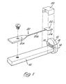
- a rectangular stainless steel support bar 10 carries at one end a transverse circular stainless steel endplate 12.
- the endplate carries a ceramic electrode support 14 on its surface facing towards the bar 10, the support 14 having two horizontal strip electrodes 16, 18.
- a ferritic, i.e. magnetic, stainless steel cantilever 20 is bolted at its thick end 20A to the bar remote from the endplate 12, and a slender second end 20B of the cantilever extends towards the ceramic support 14 and carries a plane square austenitic stainless steel vane 22, the vane is soldered to the cantilever.
- the vane carries narrow stainless steel lips 24 along all four edges at right angles to the plane of the vane; the lips can be seen more clearly in Figure 2.
- the lip nearest the ceramic support 14 is parallel to the strip electrodes 16, 18.
- the vane 22 is surrounded by a vane enclosure 26 made from stainless steel foil and spot welded to the bar 10.
- Figure 3 shows in section the bar 10, endplate 12, and ceramic support 14.
- the electrodes 16, 18 are connected to wires 28, 30 which pass through the endplate 12 in insulating jackets 32.
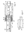
- Figure 4 illustrates in vertical section the gauge as assembled.
- the support bar 10 etc are enclosed by a stainless steel tube 34; the end of the tube 34 around the endplate 14 is surrounded by a driving coil housing 36, with magnetic driving coils 38 positioned above and below the vane 22.
- the coil housing 36 is attached to an amplifier housing 40 which encloses an amplifier circuit 42 to which the wire lead throughs 28, 30 ( Figure 3) are connected through a socket 44.
- the circuit 42 is connected at its end remote from the socket 44 to a multiway plug 46 to which the driving coils 38 are also connected.
- the tube 34 containing the support bar 10, endplate 14 etc can be separated from the housings 36, 40 as indicated by the heavy line 48, to allow the mechanical parts to be cleaned by heating.
- the vane 22 and vane enclosure 26 etc can be exposed to a low pressure atmosphere under test or a vacuum system through an end fitting (not shown).
- the magnetic coils 38 are supplied with a signal typically within the range 70 to 90 Hz or 130 to 150 Hz, so that the cantilever 20 vibrates and the vane 22 is caused to vibrate at this frequency in the enclosure 26 in a direction perpendicular to its plane.
- the decay time of the vibrations is a measure of the pressure of gas in the enclosure 26. The relationship is given by:-
- f 100, thus (3 + ⁇ 2 / f )n3.
- f can be as low as 0.34, when (3 + ⁇ 2 / f )n32.
- FIG 5 is similar to Figure 1 of the paper by the present inventor published in 1977 and referred to above and illustrates the known feature that it is advantageous to have d almost equal to b, so that sensitivity is increased.
- a further increase in sensitivity is achieved by the provision of the lips 24 extending transverse to the plane of the vane 22, because the conductance of the gap between vane lips 24 and the enclosure sides is decreased. Such lips are not present in the 1977 publication.
- Typical dimensions are a 10.6 millimetre square vane with lips about 0.8 millimetre deep, and an enclosure which is 11.2 millimetres square and 4.5 millimetres high.
- the vane and lips will typically be 0.02 millimetres thick.
- Equation (3) gives a linear relationship between damping and gas pressure up to pressures at which the mean free path of the gas molecules is no longer greater than the dimensions of the gauge; at such pressures, typically 10 torr, a change of slope occurs but the gauge can be used at these higher pressures after calibration.
- a gauge as described above can be used at pressures less than 1 torr; pressures as low as 2 x 10 -4 torr can be sensed, but it is then essential to use a cantilever of unitary construction is described above. At high pressures a composite cantilever is tolerable. By increasing the clearances between the vane and the enclosure, pressures up to 10 torr can be sensed.
- FIG. 6 illustrates the lip 24 of vane 22 adjacent the strip electrodes 16, 18.
- the vane is shown at one extreme position of its vibration, so that the lip 24 is closely adjacent electrode 16 and there is a capacitance between the electrode and the lip. At the other extreme position, shown dotted, a capacitance develops between the lip 24 and the strip electrode 18.
- the vane is earthed through the cantilever 20.
- the electrodes 16, 18 are connected one to each input of a head amplifier 54.
- the electrodes are connected through matching capacitors 56, 58 to an osciallator 60 which supplies a carrier signal.
- the capacitors provide equal capacitances to the amplifier inputs when the vane is in its rest position, and a variable capacitor 62 and parallel resistor 64 provide a zero set.
- the amplifier has a feedback resistor 66.
- the items included in circuit 42 illustrated in Figure 4 are enclosed by the chain dotted line. The arrangement is such that the carrier frequency is modulated as the capacitances between the electrodes 16 and 18 and the vane lip 24 vary with time.
- the voltage V generated at the output of amplifier 54 is a modulated voltage, the degree of modulation being a measure of the distance of the vane 22 from its rest position.
- FIG. 7 illustrates the electrical arrangement in box diagram form.
- the oscillator 60 typically at 30 KHz, supplies a carrier signal to the circuit 42 including the head amplifier 54, which supplies a modulated signal to a demodulator, amplifier and filter 68.
- the output of filter 68 is a signal proportional to the displacement of vane 22 which is supplied to a measuring and calculating unit 70 which measures the damping factor and converts the result to gas pressure for a known gas. Typically the time for the vibration of the vane to decay between two predetermined amplitudes is measured.
- Filter 68 is also connected to a vane drive system 72 which powers the magnetic driving coils 38.
- the device may be used in any orientation so that the vane vibrates horizontally or vertically or in an intermediate direction.
- the vane has been shown as square, but it can take any other shape such as elliptical, circular or rectangular.
- gauges of slightly different construction will be used to operate at high accuracy each over only part of the possible pressure range, although a single gauge could measure pressures over the whole range by suitable calibration but at lower accuracy.
Landscapes
- Physics & Mathematics (AREA)
- General Physics & Mathematics (AREA)
- Measuring Fluid Pressure (AREA)
Applications Claiming Priority (2)
| Application Number | Priority Date | Filing Date | Title |
|---|---|---|---|
| GB8109823 | 1981-03-30 | ||
| GB8109823 | 1981-03-30 |
Publications (2)
| Publication Number | Publication Date |
|---|---|
| EP0062432A1 true EP0062432A1 (de) | 1982-10-13 |
| EP0062432B1 EP0062432B1 (de) | 1985-12-04 |
Family
ID=10520749
Family Applications (1)
| Application Number | Title | Priority Date | Filing Date |
|---|---|---|---|
| EP82301448A Expired EP0062432B1 (de) | 1981-03-30 | 1982-03-19 | Schwingender Flügel-Druckmesser |
Country Status (4)
| Country | Link |
|---|---|
| US (1) | US4409840A (de) |
| EP (1) | EP0062432B1 (de) |
| DE (1) | DE3267747D1 (de) |
| GB (1) | GB2095836B (de) |
Cited By (1)
| Publication number | Priority date | Publication date | Assignee | Title |
|---|---|---|---|---|
| CH681113A5 (en) * | 1990-03-27 | 1993-01-15 | Straumann Inst Ag | Gas density and density change registering unit - has chamber for reception of gas housing vibrator and converter for exciting and detecting vibration |
Families Citing this family (8)
| Publication number | Priority date | Publication date | Assignee | Title |
|---|---|---|---|---|
| US4739664A (en) * | 1987-02-20 | 1988-04-26 | Ford Motor Company | Absolute fluid pressure sensor |
| US5363691A (en) * | 1990-09-24 | 1994-11-15 | Hydramotion Limited | Vibratile sensing instrument |
| US5655357A (en) * | 1995-05-02 | 1997-08-12 | Tilia International, Inc. | Exhaust flow rate vacuum sensor |
| US7076929B2 (en) | 2002-10-04 | 2006-07-18 | Jcs/Thg, Llc | Appliance for vacuum sealing food containers |
| US7131250B2 (en) | 2002-10-04 | 2006-11-07 | Jcs/Thg, Llp | Appliance for vacuum sealing food containers |
| US7003928B2 (en) | 2002-10-04 | 2006-02-28 | Jcs/Thg, Llc | Appliance for vacuum sealing food containers |
| TWI465706B (zh) * | 2011-01-13 | 2014-12-21 | Nat Univ Chung Hsing | 一種振幅變化與氣壓呈線性關係的氣壓量測裝置的製作方法 |
| TWI499763B (zh) * | 2011-01-13 | 2015-09-11 | Nat Univ Chung Hsing | 一種估計氣壓的方法 |
Citations (3)
| Publication number | Priority date | Publication date | Assignee | Title |
|---|---|---|---|---|
| CH453745A (de) * | 1967-06-08 | 1968-03-31 | Martin Nencki Ag | Vorrichtung zur Messung des Druckes eines gasförmigen oder flüssigen Mediums |
| US3583227A (en) * | 1969-04-08 | 1971-06-08 | Leeds & Northrup Co | Adsorbed gas type vacuum gauge |
| DD99442A1 (de) * | 1971-12-21 | 1973-08-13 |
Family Cites Families (1)
| Publication number | Priority date | Publication date | Assignee | Title |
|---|---|---|---|---|
| US2466809A (en) * | 1944-05-15 | 1949-04-12 | Ranco Inc | Pressure measuring apparatus |
-
1982
- 1982-03-19 GB GB8208160A patent/GB2095836B/en not_active Expired
- 1982-03-19 DE DE8282301448T patent/DE3267747D1/de not_active Expired
- 1982-03-19 EP EP82301448A patent/EP0062432B1/de not_active Expired
- 1982-03-24 US US06/361,255 patent/US4409840A/en not_active Expired - Fee Related
Patent Citations (3)
| Publication number | Priority date | Publication date | Assignee | Title |
|---|---|---|---|---|
| CH453745A (de) * | 1967-06-08 | 1968-03-31 | Martin Nencki Ag | Vorrichtung zur Messung des Druckes eines gasförmigen oder flüssigen Mediums |
| US3583227A (en) * | 1969-04-08 | 1971-06-08 | Leeds & Northrup Co | Adsorbed gas type vacuum gauge |
| DD99442A1 (de) * | 1971-12-21 | 1973-08-13 |
Non-Patent Citations (2)
| Title |
|---|
| JOURNAL OF PHYSICS E. SCIENTIFIC INSTRUMENTS, Vol. 3, 1970, London, G.T. ROBERTS. "The Theories of Oscillating-Vane and Rotating-Disc Pressure Gauges" pages 806 to 810 * |
| VACUUM, Vol. 28, No. 1, 1977, London, G. JONES et al.: "A Vibrating Vane Gauge for Pressure Measurement" pages 13 to 16 * |
Cited By (1)
| Publication number | Priority date | Publication date | Assignee | Title |
|---|---|---|---|---|
| CH681113A5 (en) * | 1990-03-27 | 1993-01-15 | Straumann Inst Ag | Gas density and density change registering unit - has chamber for reception of gas housing vibrator and converter for exciting and detecting vibration |
Also Published As
| Publication number | Publication date |
|---|---|
| US4409840A (en) | 1983-10-18 |
| EP0062432B1 (de) | 1985-12-04 |
| DE3267747D1 (en) | 1986-01-16 |
| GB2095836A (en) | 1982-10-06 |
| GB2095836B (en) | 1985-07-24 |
Similar Documents
| Publication | Publication Date | Title |
|---|---|---|
| US4067225A (en) | Capacitance type non-contact displacement and vibration measuring device and method of maintaining calibration | |
| US3625058A (en) | Apparatus for determining the filling level of a container | |
| US5027076A (en) | Open cage density sensor | |
| EP0282251B1 (de) | Wandler für Flüssigkeiten | |
| US5212451A (en) | Single balanced beam electrostatic voltmeter modulator | |
| US4344004A (en) | Dual function transducer utilizing displacement currents | |
| EP0062432B1 (de) | Schwingender Flügel-Druckmesser | |
| KR100347406B1 (ko) | 점성도계 | |
| US3295360A (en) | Dynamic sensor | |
| US4720682A (en) | Surface electric potential sensor | |
| JPH08338776A (ja) | センサ範囲を拡張した超小型機械式圧力ゲージ | |
| JP2002517174A (ja) | 超音波液面検出器 | |
| EP0174017A1 (de) | Kapazitive Vorrichtung zum Messen des Durchmessers einer dielektrischen Faser | |
| US5546806A (en) | Microwave vector displacement and acceleration transducer | |
| US4132110A (en) | Vibration type liquid density meter | |
| US3921087A (en) | Electrostatic field modulator having a tuning fork | |
| US2873604A (en) | Apparatus for determining vibration characteristics | |
| JP2624626B2 (ja) | 熱安定性の高いコンデンサ | |
| US7081745B2 (en) | Paramagnetic oxygen sensing apparatus and method | |
| SU746219A1 (ru) | Датчик давлени с частотным выходом | |
| JPH06504129A (ja) | ノイズ棄却型の渦流量計 | |
| EP1059521A2 (de) | Verfahren und System zur kontinuierlichen Überwachung von Teilchen | |
| JPH06300800A (ja) | 電位センサ | |
| JPH0684897B2 (ja) | 渦流測定装置 | |
| WO2002029361A1 (en) | Solid wave gyroscope |
Legal Events
| Date | Code | Title | Description |
|---|---|---|---|
| PUAI | Public reference made under article 153(3) epc to a published international application that has entered the european phase |
Free format text: ORIGINAL CODE: 0009012 |
|
| AK | Designated contracting states |
Designated state(s): CH DE FR LI |
|
| 17P | Request for examination filed |
Effective date: 19830329 |
|
| GRAA | (expected) grant |
Free format text: ORIGINAL CODE: 0009210 |
|
| AK | Designated contracting states |
Designated state(s): CH DE FR LI |
|
| REF | Corresponds to: |
Ref document number: 3267747 Country of ref document: DE Date of ref document: 19860116 |
|
| ET | Fr: translation filed | ||
| PLBE | No opposition filed within time limit |
Free format text: ORIGINAL CODE: 0009261 |
|
| STAA | Information on the status of an ep patent application or granted ep patent |
Free format text: STATUS: NO OPPOSITION FILED WITHIN TIME LIMIT |
|
| 26N | No opposition filed | ||
| PG25 | Lapsed in a contracting state [announced via postgrant information from national office to epo] |
Ref country code: LI Effective date: 19870331 Ref country code: CH Effective date: 19870331 |
|
| PG25 | Lapsed in a contracting state [announced via postgrant information from national office to epo] |
Ref country code: FR Free format text: LAPSE BECAUSE OF NON-PAYMENT OF DUE FEES Effective date: 19871130 |
|
| REG | Reference to a national code |
Ref country code: CH Ref legal event code: PL |
|
| PG25 | Lapsed in a contracting state [announced via postgrant information from national office to epo] |
Ref country code: DE Effective date: 19871201 |
|
| REG | Reference to a national code |
Ref country code: FR Ref legal event code: ST |