EP0062450A1 - Herstellung von optischen Fasern - Google Patents
Herstellung von optischen Fasern Download PDFInfo
- Publication number
- EP0062450A1 EP0062450A1 EP82301536A EP82301536A EP0062450A1 EP 0062450 A1 EP0062450 A1 EP 0062450A1 EP 82301536 A EP82301536 A EP 82301536A EP 82301536 A EP82301536 A EP 82301536A EP 0062450 A1 EP0062450 A1 EP 0062450A1
- Authority
- EP
- European Patent Office
- Prior art keywords
- core
- cladding
- fibres
- fibre
- silica
- Prior art date
- Legal status (The legal status is an assumption and is not a legal conclusion. Google has not performed a legal analysis and makes no representation as to the accuracy of the status listed.)
- Granted
Links
Images
Classifications
-
- G—PHYSICS
- G02—OPTICS
- G02B—OPTICAL ELEMENTS, SYSTEMS OR APPARATUS
- G02B6/00—Light guides; Structural details of arrangements comprising light guides and other optical elements, e.g. couplings
- G02B6/02—Optical fibres with cladding with or without a coating
- G02B6/02214—Optical fibres with cladding with or without a coating tailored to obtain the desired dispersion, e.g. dispersion shifted, dispersion flattened
- G02B6/02219—Characterised by the wavelength dispersion properties in the silica low loss window around 1550 nm, i.e. S, C, L and U bands from 1460-1675 nm
- G02B6/02276—Dispersion shifted fibres, i.e. zero dispersion at 1550 nm
-
- C—CHEMISTRY; METALLURGY
- C03—GLASS; MINERAL OR SLAG WOOL
- C03B—MANUFACTURE, SHAPING, OR SUPPLEMENTARY PROCESSES
- C03B37/00—Manufacture or treatment of flakes, fibres, or filaments from softened glass, minerals, or slags
- C03B37/01—Manufacture of glass fibres or filaments
- C03B37/02—Manufacture of glass fibres or filaments by drawing or extruding, e.g. direct drawing of molten glass from nozzles; Cooling fins therefor
- C03B37/022—Manufacture of glass fibres or filaments by drawing or extruding, e.g. direct drawing of molten glass from nozzles; Cooling fins therefor from molten glass in which the resultant product consists of different sorts of glass or is characterised by shape, e.g. hollow fibres, undulated fibres, fibres presenting a rough surface
- C03B37/023—Fibres composed of different sorts of glass, e.g. glass optical fibres, made by the double crucible technique
-
- C—CHEMISTRY; METALLURGY
- C03—GLASS; MINERAL OR SLAG WOOL
- C03B—MANUFACTURE, SHAPING, OR SUPPLEMENTARY PROCESSES
- C03B37/00—Manufacture or treatment of flakes, fibres, or filaments from softened glass, minerals, or slags
- C03B37/01—Manufacture of glass fibres or filaments
- C03B37/02—Manufacture of glass fibres or filaments by drawing or extruding, e.g. direct drawing of molten glass from nozzles; Cooling fins therefor
- C03B37/025—Manufacture of glass fibres or filaments by drawing or extruding, e.g. direct drawing of molten glass from nozzles; Cooling fins therefor from reheated softened tubes, rods, fibres or filaments, e.g. drawing fibres from preforms
- C03B37/027—Fibres composed of different sorts of glass, e.g. glass optical fibres
-
- C—CHEMISTRY; METALLURGY
- C03—GLASS; MINERAL OR SLAG WOOL
- C03C—CHEMICAL COMPOSITION OF GLASSES, GLAZES OR VITREOUS ENAMELS; SURFACE TREATMENT OF GLASS; SURFACE TREATMENT OF FIBRES OR FILAMENTS MADE FROM GLASS, MINERALS OR SLAGS; JOINING GLASS TO GLASS OR OTHER MATERIALS
- C03C13/00—Fibre or filament compositions
- C03C13/04—Fibre optics, e.g. core and clad fibre compositions
- C03C13/045—Silica-containing oxide glass compositions
-
- C—CHEMISTRY; METALLURGY
- C03—GLASS; MINERAL OR SLAG WOOL
- C03B—MANUFACTURE, SHAPING, OR SUPPLEMENTARY PROCESSES
- C03B2201/00—Type of glass produced
- C03B2201/02—Pure silica glass, e.g. pure fused quartz
-
- C—CHEMISTRY; METALLURGY
- C03—GLASS; MINERAL OR SLAG WOOL
- C03B—MANUFACTURE, SHAPING, OR SUPPLEMENTARY PROCESSES
- C03B2201/00—Type of glass produced
- C03B2201/06—Doped silica-based glasses
- C03B2201/30—Doped silica-based glasses doped with metals, e.g. Ga, Sn, Sb, Pb or Bi
- C03B2201/31—Doped silica-based glasses doped with metals, e.g. Ga, Sn, Sb, Pb or Bi doped with germanium
-
- C—CHEMISTRY; METALLURGY
- C03—GLASS; MINERAL OR SLAG WOOL
- C03B—MANUFACTURE, SHAPING, OR SUPPLEMENTARY PROCESSES
- C03B2203/00—Fibre product details, e.g. structure, shape
- C03B2203/10—Internal structure or shape details
- C03B2203/22—Radial profile of refractive index, composition or softening point
- C03B2203/24—Single mode [SM or monomode]
-
- C—CHEMISTRY; METALLURGY
- C03—GLASS; MINERAL OR SLAG WOOL
- C03B—MANUFACTURE, SHAPING, OR SUPPLEMENTARY PROCESSES
- C03B2203/00—Fibre product details, e.g. structure, shape
- C03B2203/36—Dispersion modified fibres, e.g. wavelength or polarisation shifted, flattened or compensating fibres (DSF, DFF, DCF)
-
- Y—GENERAL TAGGING OF NEW TECHNOLOGICAL DEVELOPMENTS; GENERAL TAGGING OF CROSS-SECTIONAL TECHNOLOGIES SPANNING OVER SEVERAL SECTIONS OF THE IPC; TECHNICAL SUBJECTS COVERED BY FORMER USPC CROSS-REFERENCE ART COLLECTIONS [XRACs] AND DIGESTS
- Y10—TECHNICAL SUBJECTS COVERED BY FORMER USPC
- Y10S—TECHNICAL SUBJECTS COVERED BY FORMER USPC CROSS-REFERENCE ART COLLECTIONS [XRACs] AND DIGESTS
- Y10S65/00—Glass manufacturing
- Y10S65/15—Nonoxygen containing chalogenides
- Y10S65/16—Optical filament or fiber treatment with fluorine or incorporating fluorine in final product
Definitions
- This invention relates to monomode optical fibres, i.e: fibres capable of transmitting light by propagation as a single mode.
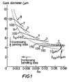
- Monomode fibres which comprise a silica-based core and cladding are physically characterised by their small dimensions and have typically a core diameter from 4 to 10 pm and a cladding diameter of at least 20 ⁇ m, preferably from 20 to 50 ⁇ m.
- the cladding is usually further surrounded.
- the refractive index of the core is normally greater than the refractive index of the cladding. This may be achieved, in a silica-based fibre, by the use of a core containing silica and germanium dioxide (the latter component serving to raise the refractive index above that of pure silica) and of a cladding having a refractive index which is similar to that of pure silica.
- Monomode optical fibres find application in telecommunications, e.g. the transmission of telephone messages. Their advantages over multimode optical fibres are now being appreciated. Single mode fibres can exhibit lower signal loss levels and may be used with higher data transmission rates than multimode fibres.
- fibres of this type should have an intrinsic loss spectrum qualitatively similar to curve 5, with two regions of low loss centred at approximately 1.3 ⁇ m and 1.55 ⁇ m respectively. These regions are termed "windows". Both the 1.3 ⁇ m window and the 1.55 ⁇ m window have been considered for the carrier signal in optical telecommunications
- the 1.3 ⁇ m window is, on balance, the more vulnerable to water-related absorption. If the water content of a fibre is allowed to increase, as may happen in practice, the water absorption peak 6 on curve 5 would not only become taller, or more intense, but it would also become wider. The initially narrower window at about 1.3 ⁇ m would be encroached upon and transmission losses in a system using this window would be increased more than those in a system using the window centred at about 1.55 pm.
- A. Kawana, T. Miya, N. Imoto, and H. Tschuchiya produced four monomode fibres having cores comprising silica and germanium dioxide.
- the core diameters ranged from 4.1 to 4.8 ⁇ m and the ⁇ n from about 0.074 to 0.084.
- ⁇ o ranged from 1.46 to 1.50 ⁇ m.
- the losses measured at 1.52 ⁇ m were high (0.8 to 1.14 dB/km), compared with that for the wider-core lower- A n fibre described in Electronics Letters 1979 and compared with the theoretical intrinsic loss.
- T. Miya, A. Kawana, Y. Terunuma, and T. Hosaka Transactions of the Institution of Electronic and Communications Engineers of Japan, volume E63, pages 514 to 519 (1980)
- ⁇ o 1.47 and 1.53 ⁇ m respectively
- the minimum loss in the 1.55 ⁇ m window was 0.5 dB/km, which is high compared with the loss in this window for wider-core lower- ⁇ n fibres described in Electronics Letters 1979 and compared with the theoretical intrinsic loss.
- Andrejco Electronics Letters, volume 15, pages 56 to 57 (1979) produced graded-index fibres having a germanium borosilicate core, an outer diameter of 110 pm, and a core/cladding ratio of 1:2, and concluded that transmission loss is independent of draw tension and temperature. They expressed the opinion that dependence of loss on such factors was typical of only phosphosilicate systems (such dependence having been previously reported by K. Yoshida, S. Sentsui, H. Shii, and T. Kuroha in Technical Digest of IOOC, Tokyo, Japan, 1977, pages 327-330). Drawing-dependent loss with a multimode fibre core containing silica, germanium dioxide, and phosphorus pentoxide has been observed also by W. Auer, K. Kimrich, I. Riegl, and U. Zwick (Proceedings of the European Fibre Optics Conference Paris, July 1980).
- the present invention is based on our surprising discovery that by drawing from preforms at a temperature of approximately 1950 0 C one may reduce the loss which.has hitherto arisen in the production of monomode fibres having zero dispersion in the 1.55 ⁇ m window, the loss in question apparently including a substantial non-intrinsic component associated with high germanium dioxide concentrations in the core.
- the present invention provides a method of producing an optical fibre capable of monomode transmission in, and having a wavelength of zero dispersion in, the 1.55 ⁇ m window and having a core comprising silica and germanium dioxide and a cladding comprising silica, said method comprising drawing an appropriate preform, characterised in that the drawing is performed at a temperature in the range from 1900°C to 2000°C.
- the preform is conveniently prepared by the MCVD (modified chemical vapour deposition) process.
- MCVD modified chemical vapour deposition
- layers of cladding and then of core material are deposited from an appropriate vapour mixture onto the inside of a silica tube which is then collapsed to yield the preform, which may be sleeved with another silica tube-before drawing, so as to achieve a particular desired aspect ratio.
- the vapour mixtures that may be used as appropriate are mixtures of pure oxygen with one or more of SiCl 4 , GeCl 4 , POC1 3 , and CC1 2 F 2 (these latter compounds providing Si, Ge, P and F respectively).
- chlorine is present as a drying agent during collapsing of the tube.
- vapour phase oxidation vapour axial deposition
- plasma modified chemical vapour deposition a method which may be used for producing the preform.
- the cladding has a refractive index close to that of pure silica (preferably slightly lower rather than slightly higher).
- the cladding may consist entirely of pure silica or it may include dopants such as phosphorus and fluorine in such amounts that their respective effects on refractive index (namely raising and lowering) substantially cancel.
- dopants such as phosphorus and fluorine in such amounts that their respective effects on refractive index (namely raising and lowering) substantially cancel.
- the latter expedient permits the use of lower deposition temperatures in MCVD.
- Preferred compositions have of the order of 1 mole per cent of P 2 O 5 .
- the cladding may have a refractive index lower than that of silica by a substantial amount (by 0.001 or more). This can be achieve.d by the use of a refractive-index-depressing dopant, e.g. fluorine, not fully compensated for by refractive-index-raising dopants, e.g. phosphorus.
- a refractive-index-depressing dopant e.g. fluorine
- the overall cladding diameter is preferably at least 20 ⁇ m and conveniently from 20 to 50 ⁇ m.
- ⁇ n and of core diameter that may be used for fibres according to the present invention may readily be found by trial and error by the man skilled in the art, but it may be noted that a ⁇ n of from 0.0075 to 0.0175, especially from 0.009 to 0.016, most especially of approximately 0.012, and of core diameters from 4 to 5.5 pm, especially from 4 to 5 pm, will in general be advantageous for a ⁇ o in the 1.55 ⁇ m window.
- the concentrations of germanium dioxide in the core will in general be from 5 to 12.5 mole per cent, especially from 6 to 11.5 mole per cent, most especially approximately 10 mole per cent.
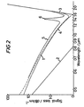
- fibres produced in accordance with the present invention should be pulled at speeds of at least 20 metre/min because of the greater loss reduction which results. We have found pulling speeds from 20 to 60 metre/min convenient.
- the preforms were produced by modified chemical vapour deposition. This was used to apply sequentially layers of cladding and core material to the inside of a silica tube which was then collapsed in the presence of chlorine to produce a preform.
- the preforms were sleeved and then drawn in a carbon resistance furnace, the temperature of whose hot zone was measured by optical pyrometry.
- the cladding both "inner” and “outer” was silica doped with phosphorus and fluorine in such quantities as to match the refractive index closely to that of pure silica.
- Examples 1, 2, and 3 and Comparative Examples lCl, lC2, 2Cl, 2C2, 3C1., and 3C2 relate to the production of a monomode fibre for which (all figures being approximate) -
- the burner traverse rate for core deposition was 0.7 of that for cladding deposition.
- the preform was sleeved in with a silica tube of 25 mm outer diameter and of 3 mm wall thickness.
- the preform was drawn at a temperature of 1950°C and at a speed of 45 metre/min.
- the resulting fibre had loss at 1.55 ⁇ m of 0.37 dB/km. (For completeness, it is noted that the loss at 1.3 ⁇ m was 0.6 dB/km.)
- the preform was drawn at temperatures and. drawing speeds of 2050°C and 55 metre/min. (Example 1C1) and 2150°C and 55 metre/min. (Example 1C2).
- the losses at 1.55 ⁇ m were 0.55 dB/km and 0.75 dB/km respectively. Had precisely the same drawing speed been used as in Example 1, then these losses would have been somewhat higher still. (For completeness, it is. noted that the losses at 1.3 ⁇ m were 0.75 and 1 dB/km respectively.)
- the preform was drawn at a temperature of 1950°C and a speed of 25 metre/min.
- the loss of the fibre produced was 0.65 dB/km. (At 1.3 ⁇ m, the loss was 0.75 dB/km.)
- the preform was drawn at a temperature and a drawing speed of 2050°C and 30 metre/min. (Comparative Example 2C1) and of 2150°C and 30 metre/min. respectively.
- the preform was drawn at a temperature of 1950°C and at a speed of 12 metre/min.
- the loss of the fibre at 1.55 ⁇ m was 0.6 dB/km. (The loss at 1.3 ⁇ m was 0.75 dB/km.)
- the preform was drawn at 2050°C and 15 metre/min. (Example 3Cl) and at 2150°C and 9 metre/min. (Example 3C2).
- the losses at 1.55 ⁇ m of the fibres produced were, respectively, 1.1 dB/km and >3 dB/km. (The losses at 1.3 ⁇ m were 1.6 and >4 dB/km respectively.)
Landscapes
- Chemical & Material Sciences (AREA)
- Engineering & Computer Science (AREA)
- Geochemistry & Mineralogy (AREA)
- Dispersion Chemistry (AREA)
- Physics & Mathematics (AREA)
- Organic Chemistry (AREA)
- Life Sciences & Earth Sciences (AREA)
- Materials Engineering (AREA)
- Optics & Photonics (AREA)
- Manufacturing & Machinery (AREA)
- General Life Sciences & Earth Sciences (AREA)
- General Physics & Mathematics (AREA)
- Chemical Kinetics & Catalysis (AREA)
- General Chemical & Material Sciences (AREA)
- Glass Compositions (AREA)
- Optical Fibers, Optical Fiber Cores, And Optical Fiber Bundles (AREA)
- Manufacture, Treatment Of Glass Fibers (AREA)
Priority Applications (1)
| Application Number | Priority Date | Filing Date | Title |
|---|---|---|---|
| AT82301536T ATE11271T1 (de) | 1981-04-08 | 1982-03-24 | Herstellung von optischen fasern. |
Applications Claiming Priority (2)
| Application Number | Priority Date | Filing Date | Title |
|---|---|---|---|
| GB8111013 | 1981-04-08 | ||
| GB8111013 | 1981-04-08 |
Publications (2)
| Publication Number | Publication Date |
|---|---|
| EP0062450A1 true EP0062450A1 (de) | 1982-10-13 |
| EP0062450B1 EP0062450B1 (de) | 1985-01-16 |
Family
ID=10521016
Family Applications (1)
| Application Number | Title | Priority Date | Filing Date |
|---|---|---|---|
| EP82301536A Expired EP0062450B1 (de) | 1981-04-08 | 1982-03-24 | Herstellung von optischen Fasern |
Country Status (6)
| Country | Link |
|---|---|
| US (1) | US4566754A (de) |
| EP (1) | EP0062450B1 (de) |
| JP (1) | JPS589834A (de) |
| AT (1) | ATE11271T1 (de) |
| CA (1) | CA1194280A (de) |
| DE (1) | DE3261900D1 (de) |
Families Citing this family (15)
| Publication number | Priority date | Publication date | Assignee | Title |
|---|---|---|---|---|
| US5033815A (en) * | 1979-10-25 | 1991-07-23 | Nippon Telephone & Telegraph | Optical transmission fiber and process for producing the same |
| US4733939A (en) * | 1984-08-18 | 1988-03-29 | Mitsubishi Metal Co., | Radiation-resistant optical conductor |
| JPS61147887A (ja) * | 1984-12-18 | 1986-07-05 | Rengo Co Ltd | 防錆剤 |
| US4973169A (en) * | 1987-06-24 | 1990-11-27 | Martin Marietta Corporation | Method and apparatus for securing information communicated through optical fibers |
| US6289698B1 (en) | 1996-08-02 | 2001-09-18 | Corning Incorporated | Method of making a fiber preform with increases in alumina concentration at radial distances |
| CA2355819A1 (en) * | 2000-08-28 | 2002-02-28 | Sumitomo Electric Industries, Ltd. | Optical fiber, method of making optical fiber preform, and method of making optical fiber |
| US6603914B2 (en) * | 2001-02-07 | 2003-08-05 | Fitel Usa Corp. | Dispersion compensating fiber with reduced splice loss and methods for making same |
| US20020186942A1 (en) * | 2001-05-01 | 2002-12-12 | Bubnov Mikhail M. | Low-loss highly phosphorus-doped fibers for Raman amplification |
| JP2002338289A (ja) * | 2001-05-14 | 2002-11-27 | Sumitomo Electric Ind Ltd | 光ファイバの製造方法 |
| US6829911B2 (en) * | 2001-08-13 | 2004-12-14 | Corning Incorporated | Making a glass optical fiber with a grating thereon |
| JP2003270470A (ja) * | 2002-03-08 | 2003-09-25 | Fitel Usa Corp | 接続損失を減少させた分散補償ファイバ、およびそれを製造する方法 |
| US20030200771A1 (en) * | 2002-04-30 | 2003-10-30 | Burke Gerald E. | Method of manufacturing phosphosilicate optical fibers and optical fibers formed therefrom |
| FR2848206B1 (fr) * | 2002-12-05 | 2005-02-25 | Cit Alcatel | Procede de realisation de preforme a fibre optique |
| KR100594062B1 (ko) * | 2004-02-13 | 2006-06-30 | 삼성전자주식회사 | 낮은 잔류 응력 불연속성을 갖는 광섬유 |
| JP4929833B2 (ja) * | 2006-05-17 | 2012-05-09 | 旭硝子株式会社 | 光ファイバ製造方法 |
Citations (4)
| Publication number | Priority date | Publication date | Assignee | Title |
|---|---|---|---|---|
| US3711262A (en) * | 1970-05-11 | 1973-01-16 | Corning Glass Works | Method of producing optical waveguide fibers |
| FR2378724A1 (fr) * | 1977-01-27 | 1978-08-25 | Nippon Sheet Glass Co Ltd | Procede et appareil de fabrication de fibres optiques en verre |
| US4165152A (en) * | 1972-11-25 | 1979-08-21 | Sumitomo Electric Industries, Ltd. | Process for producing optical transmission fiber |
| FR2453115A1 (fr) * | 1979-03-31 | 1980-10-31 | Licentia Gmbh | Procede pour la production de fibres optiques |
Family Cites Families (6)
| Publication number | Priority date | Publication date | Assignee | Title |
|---|---|---|---|---|
| US28028A (en) * | 1860-04-24 | Robert t | ||
| USRE28028E (en) | 1972-01-03 | 1974-06-04 | Method op forming an economic optical waveguide fiber | |
| DE2538313C3 (de) * | 1975-08-28 | 1981-11-05 | Heraeus Quarzschmelze Gmbh, 6450 Hanau | Verfahren zur Herstellung eines Vorproduktes für die Erzeugung eines optischen, selbstfokussierenden Lichtleiters |
| JPS53100255A (en) * | 1977-02-14 | 1978-09-01 | Nippon Telegr & Teleph Corp <Ntt> | Production of quartz glass optical fiber for light transmission |
| US4339174A (en) * | 1980-02-01 | 1982-07-13 | Corning Glass Works | High bandwidth optical waveguide |
| US4385802A (en) * | 1980-06-09 | 1983-05-31 | Corning Glass Works | Long wavelength, low-loss optical waveguide |
-
1982
- 1982-03-23 US US06/361,093 patent/US4566754A/en not_active Expired - Lifetime
- 1982-03-24 EP EP82301536A patent/EP0062450B1/de not_active Expired
- 1982-03-24 DE DE8282301536T patent/DE3261900D1/de not_active Expired
- 1982-03-24 AT AT82301536T patent/ATE11271T1/de not_active IP Right Cessation
- 1982-03-30 CA CA000399883A patent/CA1194280A/en not_active Expired
- 1982-03-31 JP JP57053628A patent/JPS589834A/ja active Pending
Patent Citations (4)
| Publication number | Priority date | Publication date | Assignee | Title |
|---|---|---|---|---|
| US3711262A (en) * | 1970-05-11 | 1973-01-16 | Corning Glass Works | Method of producing optical waveguide fibers |
| US4165152A (en) * | 1972-11-25 | 1979-08-21 | Sumitomo Electric Industries, Ltd. | Process for producing optical transmission fiber |
| FR2378724A1 (fr) * | 1977-01-27 | 1978-08-25 | Nippon Sheet Glass Co Ltd | Procede et appareil de fabrication de fibres optiques en verre |
| FR2453115A1 (fr) * | 1979-03-31 | 1980-10-31 | Licentia Gmbh | Procede pour la production de fibres optiques |
Also Published As
| Publication number | Publication date |
|---|---|
| JPS589834A (ja) | 1983-01-20 |
| DE3261900D1 (en) | 1985-02-28 |
| CA1194280A (en) | 1985-10-01 |
| EP0062450B1 (de) | 1985-01-16 |
| US4566754A (en) | 1986-01-28 |
| ATE11271T1 (de) | 1985-02-15 |
Similar Documents
| Publication | Publication Date | Title |
|---|---|---|
| EP0062450B1 (de) | Herstellung von optischen Fasern | |
| US7095940B2 (en) | Optical fiber, method for manufacturing same and optical transmission channel | |
| US8315493B2 (en) | Low loss optical fiber designs for confining optical power to low-doped regions | |
| US4385802A (en) | Long wavelength, low-loss optical waveguide | |
| EP0249230B1 (de) | Glas-Vorform für eine dispersionsverschobene optische Einzelmodenfaser und Verfahren zu deren Herstellung | |
| US5146534A (en) | SiO2 -based alkali-doped optical fiber | |
| US6690868B2 (en) | Optical waveguide article including a fluorine-containing zone | |
| Ainslie et al. | The design and fabrication of monomode optical fiber | |
| French et al. | Low‐loss fused silica optical waveguide with borosilicate cladding | |
| Gambling et al. | Special issue paper. Optical fibres based on phosphosilicate glass | |
| EP1404624A1 (de) | Verfahren zur herstellung von optischen wellenleitern umfassend einen bereich mit erhöhtem fluorgehalt | |
| CN101101354A (zh) | 掺氟光纤 | |
| US4804247A (en) | Quartz glass optical fiber | |
| EP0154026A2 (de) | Monomode optische Faser und Verfahren zur Herstellung | |
| US4335934A (en) | Single mode fibre and method of making | |
| US4327965A (en) | Single mode fibre and method of manufacture | |
| Tick et al. | Optical fiber materials | |
| GB2096351A (en) | Monomode optical fibre | |
| GB2046239A (en) | Optical fibres | |
| US6865327B2 (en) | Method of making optical fiber with reduced E-band and L-band loss peaks | |
| EP0185975A1 (de) | Verfahren zur Herstellung einer Vorform aus Glas | |
| US20120308187A1 (en) | Low Loss Aluminum Doped Optical Fiber for UV Applications | |
| OHMORI | GeO 2-P 2 O 5-Doped Silica Graded-Index Optical Fibers Fabricated by a New Profile-Control Technique | |
| Kobayashi et al. | Glass optical waveguiding technology | |
| JPH0718963B2 (ja) | 石英系光ファイバ |
Legal Events
| Date | Code | Title | Description |
|---|---|---|---|
| PUAI | Public reference made under article 153(3) epc to a published international application that has entered the european phase |
Free format text: ORIGINAL CODE: 0009012 |
|
| AK | Designated contracting states |
Designated state(s): AT BE CH DE FR GB IT LU NL SE |
|
| 17P | Request for examination filed |
Effective date: 19830308 |
|
| ITF | It: translation for a ep patent filed | ||
| GRAA | (expected) grant |
Free format text: ORIGINAL CODE: 0009210 |
|
| AK | Designated contracting states |
Designated state(s): AT BE CH DE FR GB IT LI LU NL SE |
|
| PG25 | Lapsed in a contracting state [announced via postgrant information from national office to epo] |
Ref country code: LI Effective date: 19850116 Ref country code: CH Effective date: 19850116 Ref country code: BE Effective date: 19850116 Ref country code: AT Effective date: 19850116 |
|
| REF | Corresponds to: |
Ref document number: 11271 Country of ref document: AT Date of ref document: 19850215 Kind code of ref document: T |
|
| REF | Corresponds to: |
Ref document number: 3261900 Country of ref document: DE Date of ref document: 19850228 |
|
| PG25 | Lapsed in a contracting state [announced via postgrant information from national office to epo] |
Ref country code: LU Free format text: LAPSE BECAUSE OF NON-PAYMENT OF DUE FEES Effective date: 19850331 |
|
| REG | Reference to a national code |
Ref country code: CH Ref legal event code: PL |
|
| ET | Fr: translation filed | ||
| PLBE | No opposition filed within time limit |
Free format text: ORIGINAL CODE: 0009261 |
|
| STAA | Information on the status of an ep patent application or granted ep patent |
Free format text: STATUS: NO OPPOSITION FILED WITHIN TIME LIMIT |
|
| 26N | No opposition filed | ||
| REG | Reference to a national code |
Ref country code: GB Ref legal event code: 732 |
|
| REG | Reference to a national code |
Ref country code: FR Ref legal event code: TP |
|
| ITTA | It: last paid annual fee | ||
| ITPR | It: changes in ownership of a european patent |
Owner name: CESSIONE;BRITISH TELECOMMUNICATIONS PLC |
|
| NLS | Nl: assignments of ep-patents |
Owner name: BRITISH TELECOMMUNICATIONS PLC TE LONDEN, GROOT-BR |
|
| EAL | Se: european patent in force in sweden |
Ref document number: 82301536.7 |
|
| PGFP | Annual fee paid to national office [announced via postgrant information from national office to epo] |
Ref country code: DE Payment date: 20000228 Year of fee payment: 19 |
|
| REG | Reference to a national code |
Ref country code: GB Ref legal event code: 732E |
|
| PGFP | Annual fee paid to national office [announced via postgrant information from national office to epo] |
Ref country code: FR Payment date: 20010208 Year of fee payment: 20 |
|
| PGFP | Annual fee paid to national office [announced via postgrant information from national office to epo] |
Ref country code: GB Payment date: 20010219 Year of fee payment: 20 |
|
| PGFP | Annual fee paid to national office [announced via postgrant information from national office to epo] |
Ref country code: SE Payment date: 20010223 Year of fee payment: 20 |
|
| PGFP | Annual fee paid to national office [announced via postgrant information from national office to epo] |
Ref country code: NL Payment date: 20010226 Year of fee payment: 20 |
|
| PG25 | Lapsed in a contracting state [announced via postgrant information from national office to epo] |
Ref country code: DE Free format text: LAPSE BECAUSE OF NON-PAYMENT OF DUE FEES Effective date: 20010331 |
|
| REG | Reference to a national code |
Ref country code: GB Ref legal event code: IF02 |
|
| PG25 | Lapsed in a contracting state [announced via postgrant information from national office to epo] |
Ref country code: GB Free format text: LAPSE BECAUSE OF EXPIRATION OF PROTECTION Effective date: 20020323 |
|
| PG25 | Lapsed in a contracting state [announced via postgrant information from national office to epo] |
Ref country code: NL Free format text: LAPSE BECAUSE OF EXPIRATION OF PROTECTION Effective date: 20020324 |
|
| REG | Reference to a national code |
Ref country code: GB Ref legal event code: PE20 Effective date: 20020323 |
|
| EUG | Se: european patent has lapsed |
Ref document number: 82301536.7 |
|
| NLV7 | Nl: ceased due to reaching the maximum lifetime of a patent |
Effective date: 20020324 |
|
| NLV7 | Nl: ceased due to reaching the maximum lifetime of a patent |
Effective date: 20020324 |