EP0062549A2 - Vorrichtung zum Filtern von Fluiden und in dieser Vorrichtung durchgeführtes Verfahren - Google Patents
Vorrichtung zum Filtern von Fluiden und in dieser Vorrichtung durchgeführtes Verfahren Download PDFInfo
- Publication number
- EP0062549A2 EP0062549A2 EP82400381A EP82400381A EP0062549A2 EP 0062549 A2 EP0062549 A2 EP 0062549A2 EP 82400381 A EP82400381 A EP 82400381A EP 82400381 A EP82400381 A EP 82400381A EP 0062549 A2 EP0062549 A2 EP 0062549A2
- Authority
- EP
- European Patent Office
- Prior art keywords
- arm
- fluid
- rotary
- filter element
- compartment
- Prior art date
- Legal status (The legal status is an assumption and is not a legal conclusion. Google has not performed a legal analysis and makes no representation as to the accuracy of the status listed.)
- Granted
Links
- 238000001914 filtration Methods 0.000 title claims abstract description 22
- 239000012530 fluid Substances 0.000 title claims description 27
- 238000000034 method Methods 0.000 title claims description 8
- 230000008569 process Effects 0.000 title claims description 3
- 238000005192 partition Methods 0.000 claims abstract description 19
- 230000035939 shock Effects 0.000 claims abstract description 11
- 239000012535 impurity Substances 0.000 claims description 16
- 239000012528 membrane Substances 0.000 claims description 7
- 238000004891 communication Methods 0.000 claims description 4
- 230000001105 regulatory effect Effects 0.000 claims description 2
- 239000003921 oil Substances 0.000 description 20
- 239000004744 fabric Substances 0.000 description 15
- 230000000694 effects Effects 0.000 description 6
- 239000002184 metal Substances 0.000 description 6
- 230000008929 regeneration Effects 0.000 description 6
- 238000011069 regeneration method Methods 0.000 description 6
- 230000000717 retained effect Effects 0.000 description 4
- 230000008901 benefit Effects 0.000 description 3
- 239000000446 fuel Substances 0.000 description 3
- 238000009434 installation Methods 0.000 description 3
- 230000006835 compression Effects 0.000 description 2
- 238000007906 compression Methods 0.000 description 2
- 239000000463 material Substances 0.000 description 2
- 239000002245 particle Substances 0.000 description 2
- 230000002093 peripheral effect Effects 0.000 description 2
- 238000004804 winding Methods 0.000 description 2
- 239000004952 Polyamide Substances 0.000 description 1
- 230000009471 action Effects 0.000 description 1
- 230000001276 controlling effect Effects 0.000 description 1
- 125000004122 cyclic group Chemical group 0.000 description 1
- 238000013016 damping Methods 0.000 description 1
- 230000000994 depressogenic effect Effects 0.000 description 1
- 238000002955 isolation Methods 0.000 description 1
- 238000012423 maintenance Methods 0.000 description 1
- 239000004033 plastic Substances 0.000 description 1
- 229920002647 polyamide Polymers 0.000 description 1
- 229920000728 polyester Polymers 0.000 description 1
- 238000000746 purification Methods 0.000 description 1
- 238000011084 recovery Methods 0.000 description 1
- 230000001172 regenerating effect Effects 0.000 description 1
- 230000008439 repair process Effects 0.000 description 1
- 239000010913 used oil Substances 0.000 description 1
Images

Classifications
-
- B—PERFORMING OPERATIONS; TRANSPORTING
- B01—PHYSICAL OR CHEMICAL PROCESSES OR APPARATUS IN GENERAL
- B01D—SEPARATION
- B01D27/00—Cartridge filters of the throw-away type
-
- B—PERFORMING OPERATIONS; TRANSPORTING
- B01—PHYSICAL OR CHEMICAL PROCESSES OR APPARATUS IN GENERAL
- B01D—SEPARATION
- B01D36/00—Filter circuits or combinations of filters with other separating devices
- B01D36/04—Combinations of filters with settling tanks
- B01D36/045—Combination of filters with centrifugal separation devices
-
- B—PERFORMING OPERATIONS; TRANSPORTING
- B01—PHYSICAL OR CHEMICAL PROCESSES OR APPARATUS IN GENERAL
- B01D—SEPARATION
- B01D29/00—Filters with filtering elements stationary during filtration, e.g. pressure or suction filters, not covered by groups B01D24/00 - B01D27/00; Filtering elements therefor
- B01D29/11—Filters with filtering elements stationary during filtration, e.g. pressure or suction filters, not covered by groups B01D24/00 - B01D27/00; Filtering elements therefor with bag, cage, hose, tube, sleeve or like filtering elements
- B01D29/13—Supported filter elements
- B01D29/15—Supported filter elements arranged for inward flow filtration
-
- B—PERFORMING OPERATIONS; TRANSPORTING
- B01—PHYSICAL OR CHEMICAL PROCESSES OR APPARATUS IN GENERAL
- B01D—SEPARATION
- B01D29/00—Filters with filtering elements stationary during filtration, e.g. pressure or suction filters, not covered by groups B01D24/00 - B01D27/00; Filtering elements therefor
- B01D29/50—Filters with filtering elements stationary during filtration, e.g. pressure or suction filters, not covered by groups B01D24/00 - B01D27/00; Filtering elements therefor with multiple filtering elements, characterised by their mutual disposition
- B01D29/52—Filters with filtering elements stationary during filtration, e.g. pressure or suction filters, not covered by groups B01D24/00 - B01D27/00; Filtering elements therefor with multiple filtering elements, characterised by their mutual disposition in parallel connection
-
- B—PERFORMING OPERATIONS; TRANSPORTING
- B01—PHYSICAL OR CHEMICAL PROCESSES OR APPARATUS IN GENERAL
- B01D—SEPARATION
- B01D29/00—Filters with filtering elements stationary during filtration, e.g. pressure or suction filters, not covered by groups B01D24/00 - B01D27/00; Filtering elements therefor
- B01D29/62—Regenerating the filter material in the filter
- B01D29/66—Regenerating the filter material in the filter by flushing, e.g. counter-current air-bumps
- B01D29/668—Regenerating the filter material in the filter by flushing, e.g. counter-current air-bumps with valves, e.g. rotating valves for coaxially placed filtering elements
-
- B—PERFORMING OPERATIONS; TRANSPORTING
- B01—PHYSICAL OR CHEMICAL PROCESSES OR APPARATUS IN GENERAL
- B01D—SEPARATION
- B01D29/00—Filters with filtering elements stationary during filtration, e.g. pressure or suction filters, not covered by groups B01D24/00 - B01D27/00; Filtering elements therefor
- B01D29/88—Filters with filtering elements stationary during filtration, e.g. pressure or suction filters, not covered by groups B01D24/00 - B01D27/00; Filtering elements therefor having feed or discharge devices
- B01D29/94—Filters with filtering elements stationary during filtration, e.g. pressure or suction filters, not covered by groups B01D24/00 - B01D27/00; Filtering elements therefor having feed or discharge devices for discharging the filter cake, e.g. chutes
-
- B—PERFORMING OPERATIONS; TRANSPORTING
- B01—PHYSICAL OR CHEMICAL PROCESSES OR APPARATUS IN GENERAL
- B01D—SEPARATION
- B01D35/00—Filtering devices having features not specifically covered by groups B01D24/00 - B01D33/00, or for applications not specifically covered by groups B01D24/00 - B01D33/00; Auxiliary devices for filtration; Filter housing constructions
- B01D35/14—Safety devices specially adapted for filtration; Devices for indicating clogging
- B01D35/143—Filter condition indicators
-
- B—PERFORMING OPERATIONS; TRANSPORTING
- B01—PHYSICAL OR CHEMICAL PROCESSES OR APPARATUS IN GENERAL
- B01D—SEPARATION
- B01D35/00—Filtering devices having features not specifically covered by groups B01D24/00 - B01D33/00, or for applications not specifically covered by groups B01D24/00 - B01D33/00; Auxiliary devices for filtration; Filter housing constructions
- B01D35/14—Safety devices specially adapted for filtration; Devices for indicating clogging
- B01D35/153—Anti-leakage or anti-return valves
-
- B—PERFORMING OPERATIONS; TRANSPORTING
- B01—PHYSICAL OR CHEMICAL PROCESSES OR APPARATUS IN GENERAL
- B01D—SEPARATION
- B01D2201/00—Details relating to filtering apparatus
- B01D2201/04—Supports for the filtering elements
- B01D2201/043—Filter tubes connected to plates
- B01D2201/0446—Filter tubes connected to plates suspended from plates at the upper side of the filter elements
-
- B—PERFORMING OPERATIONS; TRANSPORTING
- B01—PHYSICAL OR CHEMICAL PROCESSES OR APPARATUS IN GENERAL
- B01D—SEPARATION
- B01D2201/00—Details relating to filtering apparatus
- B01D2201/28—Position of the filtering element
- B01D2201/287—Filtering elements with a vertical or inclined rotation or symmetry axis
Definitions
- the present invention relates generally to the filtration of fluids and it relates more particularly to the filtration of oils and motor fuels.
- Continuous regeneration filtering systems are already known which are used with diesel engines and in which the oil (or fuel) taken from the engine is sent by a pump into a device containing a vertical cylindrical enclosure divided horizontally by a partition in two superimposed compartments, tubular filter elements being fixed vertically in one of the compartments by one end over the corresponding holes provided in the partition, their other end being closed.
- a rotary vertical shaft comprising a lateral arm which rotates continuously and the end of which coincides in turn and sealingly with the hole in the partition, on the underside of that -ci, which corresponds to each filter element.
- Used oil from the engine is sent by the pump to the compartment containing the rotary arm, it filters through the walls of these filter elements, from the inside to the outside, and is collected in the opposite compartment.
- the filter elements used which usually include a perforated metal tube serving as support for several ducts and a filter cloth, cannot be completely unclogged by the simple application of a back pressure through the rotary arm and must then be dismantled to be fully unclogged or cleaned of numerous impurities remaining retained in the internal sheath so that when the filtration pressure is reapplied, these impurities are again applied to the filter cloth and thereby the filtering capacity thereof is very much reduced.
- the object of the invention is to remedy these drawbacks by providing a method for filtering fluids and an automatically regenerating fluid filter by means of which the filter elements are completely freed of the impurities which they have retained, which increases their duration d 'use and therefore provides an apparatus having a very reliable operation for a very long time.
- the invention also aims to provide such a filter operating under a reduced minimum operating pressure.
- the subject of the invention is for this purpose a method for continuously filtering a fluid in an apparatus of the type comprising an enclosure divided internally into two compartments by a partition comprising at least one circular row of holes, filter elements of hollow tubular form closed to one end and fixed in one of the compartments by their opposite end open on each of said holes in the partition, a rotary tubular arm mounted in the other compartment and the end of which sweeps said circle of holes in order to coincide in turn with each from them, and into which the fluid to be filtered is admitted, under pressure, into the chamber containing the rotary arm, this fluid is passed through the filter elements from the inside to the outside, the filtered fluid is collected, in the compartment which contains the rotary arm and a pressure drop is caused through the wall of a filter element, through said rotary arm and the stream resulting from fluid laden with impurities stopped by said filter element is collected through this arm , method characterized in that, in a first phase, a filter element is isolated from the fluid inlet compartment, the opening of the rotary end of the arm is
- the invention also relates to a fluid filtration device, of the aforementioned type, characterized in that it comprises a device for applying a sudden hydraulic shock against the current through the wall of each filter element in turn.
- said device comprises means at the rotary end of the arm for closing a hole in the partition and the opening of said end of the arm and a suction pump.
- FIG. 1 Schematically shown in Figure 1 a fluid filtration installation according to the invention, which comprises an enclosure, having an inlet opening 24 and an outlet opening 25 which is usually of cylindrical shape, arranged vertically, which is divided into two superimposed chambers 13, 14, by means of an intermediate partition 15 which is pierced with holes 16 arranged in at least one circle.
- tubular filter elements 26 closed at their upper end in rotation by a motor M mounted for example at the top of the device.
- the lower end of the hollow shaft section 18 which communicates with the lower end of the flow regulator 19 is connected to the input of a pump P, the discharge of which is connected to a device 22 for regeneration indicator, the output of which is itself connected to a centrifugal purifier 23 as will be described below.
- the regulator 19 comprises a body or casing which can be cylindrical and which communicates by its end opposite the arm 20 with the interior space of the shaft section 18 which extends towards the exterior of the apparatus through the bottom of the compartment 14 by means of a rotary watertight seal 53 and the regulator internally comprises a sleeve 54 consisting of an elastic membrane fixed in a leaktight manner by the periphery of its ends opposite the internal wall of the casing.
- An orifice 55 provided with a valve communicates with the space delimited between the wall of the regulator housing and the membrane 54.
- This regeneration indicator device 22 comprises a hollow body 56 having for example at roughly the shape of a cube open on one face and delimiting an interior chamber 57 crossed by an axis 58 biased by a spring 59 and carrying a shutter 60 so that it is applied to an orifice 61 provided in the face of the body opposite its open face.
- the axis 58 protrudes outside the body 22 and an index 63 is wedged on its end.
- the body of the device 22 is adapted to be fixed with its orifice 61 connected to the outlet end of the shaft section 18 outside the device, its open face being closed by means of a plate comprising a orifice (not shown) and adapted to be connected by a conduit 62 to the inlet of the centrifugal purification device 23.
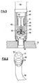
- a filter element 26 which comprises a tubular body 28 of perforated metal shown partially on a larger scale in Figure 4, on the outer surface of which is applied a filter cloth 29 for example polyamide itself covered with an outer sheath 30, for example made of polyester comprising warp threads 31 and weft threads 32.
- the assembly is surrounded by a metallic wire 33 helically wound with a slight radial clearance (which is exaggerated in FIG. 4 for the sake of clarity).
- the filter elements of the prior art in which the filtering takes place from the outside to the inside usually comprise on the perforated metal tubular support an internal sheath similar to the sheath 30, disposed between the support and the wire cloth sleeve trante and it will be noted that the filter element according to the invention does not have an internal sheath, which constitutes an economy compared to the prior art.
- the sheath 30 comprises an annular weft thread 32 having a diameter greater than that of the warp thread 31, in a proportion of 1 to 2.
- the weft thread has a diameter of 4/10 mm and the warp thread has a diameter of 2/10 mm.
- the metal wire 33 is wound helically with its relatively close turns, for a purpose which will be described below.
- the lower end 40 of the sleeve 34 is received in leaktight fit by means of the seal 35 in the upper end of a retaining device as known per se and designated as a whole by the reference 41 and shown in section in the figure 5.
- the retaining device 41 comprises a hollow body 42 having at one end an internal diameter corresponding to the external diameter of the end 40 of the sleeve 34.
- the body 42 has a bore in which is disposed a helical compression spring 43 which bears at one end on an internal shoulder 44 of the bore and whose opposite end bears on a flange of a guide member 45 of cruciform section carrying at its opposite end a shutter 46 held by a screw 47 and adapted to bear in a sealed manner by means of a seal 48 on an annular seat 49 formed inside the body.
- a helical compression spring 43 which bears at one end on an internal shoulder 44 of the bore and whose opposite end bears on a flange of a guide member 45 of cruciform section carrying at its opposite end a shutter 46 held by a screw 47 and adapted to bear in a sealed manner by means of a seal 48 on an annular seat 49 formed inside the body.
- the end of the body 42 beyond the shutter 46 is adapted to be fixed in leaktight manner to a hole 16 in the partition 15.
- the assembly constitutes a valve arranged so that the end of the guide member 45 is pushed back against the action of the spring 43 when the end 40 of a filter element 26 is introduced and fixed in the body 42, thus moving the shutter 46 away from its seat 49 and opening the communication between the interior space of the filter element 26 and the hole 16 through the partition 15.
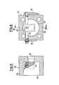
- the lower surface of the partition 15 is polished so as to cooperate in sealed contact with the upper surface 50 also polished of the pad 21 fixed to the end of the rotary arm 20, which can consist of a plate 50, having an opening 51 and having along the circle described a length such that the part 52 of the plate 50 completely closes a hole 16 while at the same time the opening 51 is itself closed, at a given instant of the rotation movement of the arm 20 .
- a fluid for example polluted oil from a diesel engine, is brought under pressure by means of a pump (not shown) to the inlet opening 24 and into the compartment 14.
- the rotary arm 20 being in contact through his closure member 21 with the underside of the partition 15 in line with a hole 16 communicating with a filter element 26, the interior of the other filter elements 26 communicates freely with the compartment 14 and the pressurized oil enters the inside the filter elements through the holes 16.
- the polluted oil passes through the orifices 39 of the support 28 then is filtered by the filter cloth 29 and the external sheath 30.
- the oil exiting through the walls of the filter elements 26 fills the compartment 13 from where it is returned to the engine by through the outlet opening 25.
- the pump P being in continuous operation applies a vacuum in the flow regulator 19 and in the arm 20, vacuum which is maintained as long as the opening 51 is closed by the contact of the closing member 21 with the partition 15 , between holes 16.
- the corresponding filter element 26 is isolated from the compartment 14 into which the polluted oil enters under pressure and the pressure drop across its wall is momentarily canceled. Since no pressure is exerted from the inside to the outside, the impurities are no longer applied to the internal wall of the filter element.
- the sudden hydraulic shock which results has the effect of dislodging the impurities retained inside the filter element 26 and of driving them by the arm through the regulator 19 and the device 22 as far as the purifier 23 with a current oil under pressure.
- the arm 20 continuing its rotation then closes the hole 16 corresponding to the filter element 26 according to whether it insulates from the chamber 14, then the opening 51 comes to coincide with this hole to in turn subject this element to the same hydraulic shock.
- the filter elements 26 are thus subjected in turn cyclically to the hydraulic shock effect which occurs each time the opening 51 coincides with a hole 16, from the interior of the compartment 13 through the filter element, driving out impurities through the arm 20.
- the oil current carrying away the impurities is projected with successive pulses towards the outside.
- the volume of oil charged with impurities and discharged by the pump has the effect of moving the shutter 60 of the device 22 by driving the axis 58 and therefore the index 63, which thus performs an oscillating movement indicating the operation satisfied with the device.
- the centrifugal purifier 23 should preferably receive a continuous stream of oil.
- the flow regulator 19 is previously charged by means of compressed air introduced by the valve 55 which inflates and deforms the membrane 54 inwards, thereby throttling the passage section in the casing. of the regulator.
- the pressure has the effect of pushing the membrane 54 outward, which is allowed by the pressure of the compressed air between the membrane and the body wall.
- the membrane yields elastically under oil pressure and the internal volume of the regulator increases, which has the effect of damping the pressure wave produced by the flow of oil from the filter element.
- the arm 20 continues to rotate, the successive oil flow rates under pressure from each filter element 26 in turn are thus regulated by the regulator 19.
- the index 23 of the device 22 instead of making an oscillating movement indicating the successive pressure waves produced by the oil expelled from the filter elements assumes an approximately stable average position. which indicates a correct continuous filtration in the apparatus and the arrival of an almost continuous stream of oil to the centrifugal purifier 23 which can thus function satisfactorily and the purified oil is collected at the outlet 64 of the purifier to be returned to the engine.
- the process and the apparatus according to the invention make it possible to obtain an almost instantaneous unclogging of the filter elements after having first stabilized the pressure inside and outside of the filter elements by closing the outlet of the latter. .
- the apparatus according to the invention also has an important advantage due to the presence of valves interposed between the plate and the filter elements, which are adapted to be opened automatically when a filter element is placed in place, and to close when the filter element is removed. Consequently, if necessary, if a filter element is for example damaged, it is possible to remove it to repair it and to put the device back into operation instantly, the corresponding hole 16 being automatically closed by the valve. In service, when the closure member 21 coincides with the hole corresponding to the location devoid of filter element, there is simply a zero phase of operation.
- the filter cloth is effectively supported by the network of holes in the support, 28, which is denser than in filter elements of a similar type used in the devices of the prior art, when it is applied to it by external pressure.
- the outer sheath 30 When it is spaced from the support 28, it is supported by the outer sheath 30. It has been found that this outer sheath produced as indicated above was entirely sufficient to ensure appropriate maintenance of the filter cloth until drops of pressure from 3 to 5 bar at temperatures of the fluid to be filtered up to 50 °.
- the plastic material of the weft and warp threads of the sheath no longer offers sufficient resistance and the metal wire 33 helically wound with relatively tight turns around the sheath provides the latter with support. sufficient to perform filtering operations at temperatures up to 90 ° C and with a pressure drop up to 10 bar. It is possible, if desired, to obtain satisfactory operation at even higher temperatures and pressures by providing a metal wire 33 of suitable diameter and the winding pitch of which will be sufficiently tight.
- each filter element can be disposed and easily held in place in the device, adjusted on the upper end of the valve body, the spring 38 then taking support on the cover of the device and now l filter element in place.
- the device according to the invention provides numerous improvements and advantages compared to devices of the same type of the prior art with means for controlling the operation and recovery of the polluted filtered fluid contained in the filter elements. .
- the vacuum created between the pump and the filter element increases the pressure difference which prevails at the level of the filter material of the element.
- 1.5 bar of outlet pressure is enough to obtain 2 bars of differential pressure, a value necessary for proper regeneration of the filter elements.
Landscapes
- Chemical & Material Sciences (AREA)
- Chemical Kinetics & Catalysis (AREA)
- Filtration Of Liquid (AREA)
- Electrical Discharge Machining, Electrochemical Machining, And Combined Machining (AREA)
- External Artificial Organs (AREA)
- Filtering Materials (AREA)
- Centrifugal Separators (AREA)
- Filtering Of Dispersed Particles In Gases (AREA)
Priority Applications (1)
| Application Number | Priority Date | Filing Date | Title |
|---|---|---|---|
| AT82400381T ATE16462T1 (de) | 1981-04-03 | 1982-03-05 | Vorrichtung zum filtern von fluiden und in dieser vorrichtung durchgefuehrtes verfahren. |
Applications Claiming Priority (2)
| Application Number | Priority Date | Filing Date | Title |
|---|---|---|---|
| FR8106722A FR2502970B1 (fr) | 1981-04-03 | 1981-04-03 | Procede de filtration de fluides et appareil pour la mise en oeuvre de ce procede |
| FR8106722 | 1981-04-03 |
Publications (3)
| Publication Number | Publication Date |
|---|---|
| EP0062549A2 true EP0062549A2 (de) | 1982-10-13 |
| EP0062549A3 EP0062549A3 (en) | 1983-02-16 |
| EP0062549B1 EP0062549B1 (de) | 1985-11-13 |
Family
ID=9256975
Family Applications (1)
| Application Number | Title | Priority Date | Filing Date |
|---|---|---|---|
| EP82400381A Expired EP0062549B1 (de) | 1981-04-03 | 1982-03-05 | Vorrichtung zum Filtern von Fluiden und in dieser Vorrichtung durchgeführtes Verfahren |
Country Status (13)
| Country | Link |
|---|---|
| US (1) | US4462916A (de) |
| EP (1) | EP0062549B1 (de) |
| JP (1) | JPS588525A (de) |
| KR (1) | KR830009795A (de) |
| AT (1) | ATE16462T1 (de) |
| AU (1) | AU8187582A (de) |
| BR (1) | BR8201890A (de) |
| DD (1) | DD203232A5 (de) |
| DE (1) | DE3267353D1 (de) |
| FR (1) | FR2502970B1 (de) |
| MX (1) | MX156717A (de) |
| SU (1) | SU1232126A3 (de) |
| ZA (1) | ZA822058B (de) |
Cited By (3)
| Publication number | Priority date | Publication date | Assignee | Title |
|---|---|---|---|---|
| EP0875286A1 (de) * | 1997-04-29 | 1998-11-04 | Hydac Filtertechnik GmbH | Filtervorrichtung mit Membranmodul |
| WO2009062644A1 (de) * | 2007-11-16 | 2009-05-22 | Hydac Process Technology Gmbh | Filtervorrichtung |
| CN120501953A (zh) * | 2025-05-27 | 2025-08-19 | 华中科技大学同济医学院附属协和医院 | 临床护理的引流装置 |
Families Citing this family (36)
| Publication number | Priority date | Publication date | Assignee | Title |
|---|---|---|---|---|
| USRE34218E (en) | 1983-09-02 | 1993-04-13 | Easily-cleanable filters | |
| IL75473A0 (en) * | 1985-06-10 | 1985-10-31 | Drori Mordeki | Improved disc filter |
| US4978450A (en) | 1986-02-11 | 1990-12-18 | Mordeki Drori | Filtering element |
| IL83329A (en) | 1987-07-26 | 1991-08-16 | Drori Mordeki | Filter apparatus |
| EP0347477A1 (de) | 1988-06-21 | 1989-12-27 | Mordeki Drori | Filtrationsvorrichtung |
| US5015379A (en) | 1988-03-16 | 1991-05-14 | Mordeki Drori | Coiled filter strip with upstream and downstream butt ends |
| DE3834642A1 (de) * | 1988-10-11 | 1990-04-12 | Herrmann Karl Heinz | Filteranordnung |
| IL88940A0 (en) | 1989-01-12 | 1989-08-15 | Drori Mordeki | Filter apparatus |
| NL8902637A (nl) * | 1989-10-25 | 1991-05-16 | Esmil Water Systems Bv | Filtersysteem. |
| NO175738C (no) * | 1992-01-16 | 1995-05-04 | Ola Rindal | Fremgangsmåte og anordning ved dukrensing i posefiltre |
| US5280890A (en) * | 1992-01-22 | 1994-01-25 | Miner Enterprises, Inc. | Radial elastomer compression spring |
| WO1996006667A2 (en) * | 1994-09-01 | 1996-03-07 | Pyrox, Inc. | High capacity ultrafiltration apparatus |
| RU2134142C1 (ru) * | 1998-05-26 | 1999-08-10 | Безгубова Людмила Сергеевна | Фильтр для очистки жидкости и способ очистки фильтра |
| DE19956859A1 (de) | 1999-11-25 | 2001-06-07 | Hydac Filtertechnik Gmbh | Rückspülfiltervorrichtung |
| US6758344B2 (en) | 2002-02-21 | 2004-07-06 | Gordon Construction, Inc. | Self-cleaning fluid filter system |
| US20060021920A1 (en) * | 2004-08-02 | 2006-02-02 | Forbes Robert C | Pond filters |
| DE102005013673A1 (de) * | 2005-03-24 | 2006-09-28 | Hydac Process Technology Gmbh | Filteranlage und Verfahren zum Betrieb der Filteranlage |
| NO20052522L (no) * | 2005-05-26 | 2006-11-27 | Stromme Betex As | Anordning ved filter |
| US8029584B2 (en) | 2007-06-06 | 2011-10-04 | Castronovo Charles A | Vacuum cleaners with self-cleaning filtration, and other self-cleaning filters |
| CN101940852B (zh) * | 2009-07-08 | 2012-09-05 | 王克涛 | 一种可反清洗的过滤器 |
| CN101900136B (zh) * | 2010-09-04 | 2012-08-22 | 东北石油大学 | 转动式防堵塞过滤器 |
| NO332335B1 (no) * | 2010-11-18 | 2012-09-03 | Ocea As | Filterarrangement og fremgangsmåte for fjerning av partikler i en væske |
| JP5916536B2 (ja) * | 2012-06-27 | 2016-05-11 | Jfeエンジニアリング株式会社 | 生物捕捉除去装置及びバラスト水処理装置 |
| JP5916537B2 (ja) * | 2012-06-27 | 2016-05-11 | Jfeエンジニアリング株式会社 | 濾過体、これを有する濾過装置及び海水処理装置 |
| JP6084071B2 (ja) * | 2013-02-28 | 2017-02-22 | Jfeエンジニアリング株式会社 | バラスト水用海水濾過装置 |
| DE102013214075A1 (de) | 2013-07-18 | 2015-01-22 | Fraunhofer-Gesellschaft zur Förderung der angewandten Forschung e.V. | Gewebe mit Polymerschicht |
| WO2016107878A1 (en) * | 2014-12-30 | 2016-07-07 | Grundfos Holding A/S | Tubular elements for cake filtration and method of providing a filtration cake |
| US11007742B2 (en) * | 2016-03-08 | 2021-05-18 | Vwater Technologies, Llc. | Dynamic separation and filtration |
| CN107335284B (zh) * | 2017-08-29 | 2023-03-31 | 中国建筑设计研究院有限公司 | 一种厨余垃圾固液分离装置 |
| CN107754420B (zh) * | 2017-09-26 | 2023-04-28 | 杭州水享智能科技集团有限公司 | 一种新型前置过滤器 |
| US11433324B2 (en) | 2019-02-25 | 2022-09-06 | Vivoblu Inc | Water filtration methods and systems |
| JP7292904B2 (ja) * | 2019-03-06 | 2023-06-19 | 住友重機械工業株式会社 | オイルセパレータ、フィルターエレメント、および極低温冷凍機用圧縮機 |
| CN112587976A (zh) * | 2020-11-04 | 2021-04-02 | 洛阳功航机械科技有限公司 | 车载式催化油浆在线过滤装置 |
| USD1069978S1 (en) | 2021-03-08 | 2025-04-08 | Vivoblu Inc | Filter wingnut |
| USD987024S1 (en) | 2021-06-09 | 2023-05-23 | Vivoblu Inc | Filter cartridge housing |
| CN113648715B (zh) * | 2021-10-20 | 2022-02-11 | 品孚罗特过滤设备(北京)有限公司 | 连续过滤多腔轮流下线复合过滤装置 |
Family Cites Families (13)
| Publication number | Priority date | Publication date | Assignee | Title |
|---|---|---|---|---|
| US3132099A (en) * | 1959-11-26 | 1964-05-05 | Eilhauer Friedrich | Filter and method of making same |
| US3193100A (en) * | 1960-08-24 | 1965-07-06 | A E Broughton & Co Inc | Liquid filter system |
| GB1052157A (de) * | 1964-04-17 | |||
| US3317048A (en) * | 1964-06-29 | 1967-05-02 | Bendix Corp | Filter unit |
| FR1418099A (fr) * | 1964-08-31 | 1965-11-19 | Filtre automatique | |
| US3280980A (en) * | 1966-01-03 | 1966-10-25 | William R King | Self-cleaning filter |
| US3425557A (en) * | 1966-04-04 | 1969-02-04 | Universal Filters Inc | Backwash means for dual filter elements |
| US3502214A (en) * | 1968-03-04 | 1970-03-24 | Bowser Inc | Check valve for filter apparatus |
| DE1761827B1 (de) * | 1968-07-11 | 1972-02-03 | Tischer Ernst Max | Fluessigkeitsfilter mit selbsttaetiger Reinigung |
| US3850803A (en) * | 1973-06-27 | 1974-11-26 | R Adams | Atmospheric pressure filter |
| JPS5172779A (de) * | 1974-12-20 | 1976-06-23 | Nippon Filcon Kk | |
| DE2620435A1 (de) * | 1976-05-08 | 1977-11-24 | Mann & Hummel Filter | In eine druckleitung einfuegbarer fluessigkeitsfilter |
| SE7902710L (sv) * | 1979-03-27 | 1980-09-22 | Forsheda Gummifabrik Ab | Filteranordning |
-
1981
- 1981-04-03 FR FR8106722A patent/FR2502970B1/fr not_active Expired
-
1982
- 1982-03-05 DE DE8282400381T patent/DE3267353D1/de not_active Expired
- 1982-03-05 EP EP82400381A patent/EP0062549B1/de not_active Expired
- 1982-03-05 AT AT82400381T patent/ATE16462T1/de not_active IP Right Cessation
- 1982-03-24 AU AU81875/82A patent/AU8187582A/en not_active Abandoned
- 1982-03-25 ZA ZA822058A patent/ZA822058B/xx unknown
- 1982-03-30 US US06/363,488 patent/US4462916A/en not_active Expired - Lifetime
- 1982-04-01 DD DD82238657A patent/DD203232A5/de not_active IP Right Cessation
- 1982-04-02 JP JP57055268A patent/JPS588525A/ja active Pending
- 1982-04-02 SU SU823420425A patent/SU1232126A3/ru active
- 1982-04-02 BR BR8201890A patent/BR8201890A/pt unknown
- 1982-04-02 MX MX192135A patent/MX156717A/es unknown
- 1982-04-03 KR KR1019820001516A patent/KR830009795A/ko not_active Ceased
Cited By (6)
| Publication number | Priority date | Publication date | Assignee | Title |
|---|---|---|---|---|
| EP0875286A1 (de) * | 1997-04-29 | 1998-11-04 | Hydac Filtertechnik GmbH | Filtervorrichtung mit Membranmodul |
| WO2009062644A1 (de) * | 2007-11-16 | 2009-05-22 | Hydac Process Technology Gmbh | Filtervorrichtung |
| US8216469B2 (en) | 2007-11-16 | 2012-07-10 | Hydac Process Technology Gmbh | Filter device |
| CN101854994B (zh) * | 2007-11-16 | 2012-11-14 | Hydac处理技术有限公司 | 过滤设备 |
| US8518274B2 (en) | 2007-11-16 | 2013-08-27 | Hydac Process Technology Gmbh | Filter device operating method |
| CN120501953A (zh) * | 2025-05-27 | 2025-08-19 | 华中科技大学同济医学院附属协和医院 | 临床护理的引流装置 |
Also Published As
| Publication number | Publication date |
|---|---|
| DE3267353D1 (en) | 1985-12-19 |
| ATE16462T1 (de) | 1985-11-15 |
| SU1232126A3 (ru) | 1986-05-15 |
| EP0062549A3 (en) | 1983-02-16 |
| DD203232A5 (de) | 1983-10-19 |
| KR830009795A (ko) | 1983-12-23 |
| BR8201890A (pt) | 1983-03-08 |
| ZA822058B (en) | 1983-02-23 |
| FR2502970A1 (fr) | 1982-10-08 |
| JPS588525A (ja) | 1983-01-18 |
| FR2502970B1 (fr) | 1988-06-24 |
| EP0062549B1 (de) | 1985-11-13 |
| MX156717A (es) | 1988-09-28 |
| US4462916A (en) | 1984-07-31 |
| AU8187582A (en) | 1982-10-07 |
Similar Documents
| Publication | Publication Date | Title |
|---|---|---|
| EP0062549B1 (de) | Vorrichtung zum Filtern von Fluiden und in dieser Vorrichtung durchgeführtes Verfahren | |
| EP0787032B1 (de) | Vorrichtung zum behandlung von flüssigkeit mittels filtration und zentrifugation | |
| EP0145552B1 (de) | Filter mit zwei unterschiedlichen Filteraufbauten | |
| CH433194A (fr) | Dispositif de filtration mécanique multicellulaire à nettoyage automatique continu pour liquides sous pression | |
| EP1959809B1 (de) | Vorrichtung zur reinigung eines staubsaugerfilters | |
| EP0121105A1 (de) | Vorrichtung zur Filterung von Flüssigkeiten | |
| EP0579798B1 (de) | Anlage und filtrationsmodul fuer flüssigkeiten | |
| EP0078727B1 (de) | Einrichtung zum Filtrieren von, in einer Flüssigkeit sich befindenden, vielartigen Verunreinigungen | |
| CA2060035C (fr) | Machine a cafe automatique | |
| FR2677893A1 (fr) | Filtre a fluide comportant deux ensembles de filtration. | |
| FR2550710A1 (fr) | Installation de filtration d'eaux chargees de particules minerales et/ou vegetales | |
| EP0136202A1 (de) | Filter mit einer Reinigungseinrichtung versehen | |
| EP0019554A1 (de) | Filtrationsvorrichtung | |
| EP0299898B1 (de) | Verfahren und Einrichtung zur automatischen Reinigung von Luftfilterschläuchen | |
| EP1554029B1 (de) | Verteiler für rotierendes filter und rotierendes filter mit einem solchen verteiler | |
| EP0198421B1 (de) | Verfahren und Vorrichtung zum Filtrieren einer Suspension von Teilchen in einer Flüssigkeit | |
| EP4157479B1 (de) | Rotationsfilter und zugehöriges filterverfahren | |
| FR2514411A1 (fr) | Procede et equipement pour regenerer en fonctionnement les huiles de graissage | |
| FR2493721A1 (fr) | Filtre a auto-nettoyage | |
| EP0149931A1 (de) | Filter mit mehreren Aufnahmekammern für das Filtrat und für eine andere Flüssigkeit welche durch den Rückstand den Hauptfiltrierung gebildet ist | |
| FR2513536A1 (fr) | Dispositif de filtration d'un liquide | |
| EP0888164A1 (de) | Verfahren und vorrichtung zur selektiven abscheidung von mindestens einem bestandteil aus einer gasmischung | |
| FR2528912A1 (fr) | Dispositif de traitement de carburant et circuit de carburant en constituant l'application | |
| FR2873616A1 (fr) | Pressoir pour matiere telle que de la vendange | |
| FR2525321A3 (fr) | Dispositif pour la regeneration d'huile lubrifiante en cours de service |
Legal Events
| Date | Code | Title | Description |
|---|---|---|---|
| PUAI | Public reference made under article 153(3) epc to a published international application that has entered the european phase |
Free format text: ORIGINAL CODE: 0009012 |
|
| AK | Designated contracting states |
Designated state(s): AT BE CH DE GB IT LU NL SE |
|
| PUAL | Search report despatched |
Free format text: ORIGINAL CODE: 0009013 |
|
| AK | Designated contracting states |
Designated state(s): AT BE CH DE GB IT LI LU NL SE |
|
| 17P | Request for examination filed |
Effective date: 19830706 |
|
| GRAA | (expected) grant |
Free format text: ORIGINAL CODE: 0009210 |
|
| AK | Designated contracting states |
Designated state(s): AT BE CH DE GB IT LI LU NL SE |
|
| PG25 | Lapsed in a contracting state [announced via postgrant information from national office to epo] |
Ref country code: NL Effective date: 19851113 Ref country code: IT Free format text: LAPSE BECAUSE OF FAILURE TO SUBMIT A TRANSLATION OF THE DESCRIPTION OR TO PAY THE FEE WITHIN THE PRESCRIBED TIME-LIMIT;WARNING: LAPSES OF ITALIAN PATENTS WITH EFFECTIVE DATE BEFORE 2007 MAY HAVE OCCURRED AT ANY TIME BEFORE 2007. THE CORRECT EFFECTIVE DATE MAY BE DIFFERENT FROM THE ONE RECORDED. Effective date: 19851113 Ref country code: AT Effective date: 19851113 |
|
| REF | Corresponds to: |
Ref document number: 16462 Country of ref document: AT Date of ref document: 19851115 Kind code of ref document: T |
|
| PG25 | Lapsed in a contracting state [announced via postgrant information from national office to epo] |
Ref country code: SE Effective date: 19851130 |
|
| REF | Corresponds to: |
Ref document number: 3267353 Country of ref document: DE Date of ref document: 19851219 |
|
| NLV1 | Nl: lapsed or annulled due to failure to fulfill the requirements of art. 29p and 29m of the patents act | ||
| PLBE | No opposition filed within time limit |
Free format text: ORIGINAL CODE: 0009261 |
|
| STAA | Information on the status of an ep patent application or granted ep patent |
Free format text: STATUS: NO OPPOSITION FILED WITHIN TIME LIMIT |
|
| 26N | No opposition filed | ||
| EPTA | Lu: last paid annual fee | ||
| PGFP | Annual fee paid to national office [announced via postgrant information from national office to epo] |
Ref country code: LU Payment date: 19960201 Year of fee payment: 15 |
|
| PGFP | Annual fee paid to national office [announced via postgrant information from national office to epo] |
Ref country code: DE Payment date: 19960221 Year of fee payment: 15 |
|
| PGFP | Annual fee paid to national office [announced via postgrant information from national office to epo] |
Ref country code: GB Payment date: 19960227 Year of fee payment: 15 |
|
| PGFP | Annual fee paid to national office [announced via postgrant information from national office to epo] |
Ref country code: CH Payment date: 19960311 Year of fee payment: 15 |
|
| PGFP | Annual fee paid to national office [announced via postgrant information from national office to epo] |
Ref country code: BE Payment date: 19960412 Year of fee payment: 15 |
|
| PG25 | Lapsed in a contracting state [announced via postgrant information from national office to epo] |
Ref country code: LU Free format text: LAPSE BECAUSE OF NON-PAYMENT OF DUE FEES Effective date: 19970305 Ref country code: GB Effective date: 19970305 |
|
| PG25 | Lapsed in a contracting state [announced via postgrant information from national office to epo] |
Ref country code: LI Effective date: 19970331 Ref country code: CH Effective date: 19970331 Ref country code: BE Effective date: 19970331 |
|
| BERE | Be: lapsed |
Owner name: SOC. D'EXPLOITATION DES ETS RELLUMIX Effective date: 19970331 |
|
| GBPC | Gb: european patent ceased through non-payment of renewal fee |
Effective date: 19970305 |
|
| REG | Reference to a national code |
Ref country code: CH Ref legal event code: PL |
|
| PG25 | Lapsed in a contracting state [announced via postgrant information from national office to epo] |
Ref country code: DE Effective date: 19971202 |