EP0062688A1 - Filmführung, insbesondere für Filmbetrachter, Projektoren, Vergrösserungsgeräte oder dgl. - Google Patents
Filmführung, insbesondere für Filmbetrachter, Projektoren, Vergrösserungsgeräte oder dgl. Download PDFInfo
- Publication number
- EP0062688A1 EP0062688A1 EP19810102870 EP81102870A EP0062688A1 EP 0062688 A1 EP0062688 A1 EP 0062688A1 EP 19810102870 EP19810102870 EP 19810102870 EP 81102870 A EP81102870 A EP 81102870A EP 0062688 A1 EP0062688 A1 EP 0062688A1
- Authority
- EP
- European Patent Office
- Prior art keywords
- film
- frame part
- film guide
- guide according
- frame
- Prior art date
- Legal status (The legal status is an assumption and is not a legal conclusion. Google has not performed a legal analysis and makes no representation as to the accuracy of the status listed.)
- Granted
Links
- 238000009423 ventilation Methods 0.000 claims description 3
- 238000011161 development Methods 0.000 description 2
- 230000018109 developmental process Effects 0.000 description 2
- 230000007704 transition Effects 0.000 description 2
- 230000006978 adaptation Effects 0.000 description 1
- 238000010586 diagram Methods 0.000 description 1
- 238000011010 flushing procedure Methods 0.000 description 1
- 230000009191 jumping Effects 0.000 description 1
Images


Classifications
-
- G—PHYSICS
- G03—PHOTOGRAPHY; CINEMATOGRAPHY; ANALOGOUS TECHNIQUES USING WAVES OTHER THAN OPTICAL WAVES; ELECTROGRAPHY; HOLOGRAPHY
- G03B—APPARATUS OR ARRANGEMENTS FOR TAKING PHOTOGRAPHS OR FOR PROJECTING OR VIEWING THEM; APPARATUS OR ARRANGEMENTS EMPLOYING ANALOGOUS TECHNIQUES USING WAVES OTHER THAN OPTICAL WAVES; ACCESSORIES THEREFOR
- G03B1/00—Film strip handling
- G03B1/42—Guiding, framing, or constraining film in desired position relative to lens system
- G03B1/44—Guides engaging edge of film
Definitions
- the invention relates to a film guide, in particular for film viewers, projectors or the like.
- a picture window for the image edge limitation and film position definition, the opening width transverse to the film transport direction is smaller than the width of the film transport path.
- Such picture windows have a defined position to the optics and have the effect that the picture window plane or the film lying there is displayed sharply on the screen or the screen.
- the transported film has an unavoidable curvature caused by the image layer.
- the heat emitted by the light source has a correspondingly long effect on the film and causes an additional curvature or a change in the curvature depth.
- the optics in known devices must be dimensioned such that they take into account the largest curvature that occurs, i.e. to get a large depth of field in the DIA area because of the jumping DIA.
- this has the consequence that, especially in the case of projectors, the projected image is small relative to the distance of the projector from the screen, because of the large focal length of the lens required for the large depth of field.
- the sharpness of the projectors that are common on the market often has to be adjusted during operation because in the case of non-glazed slides, the maximum curvature that occurs is still larger than intended, depending on how well or badly framed.
- the invention has for its object to scrape a film guide for film viewers, projectors or the like.
- a film guide for film viewers, projectors or the like.
- sufficient sharpness of the image can be achieved even if the focal length is chosen to be smaller than usual enable a large image relative to the distance of the device from the screen.
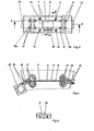
- FIG. 1 shows a projector 1 with optics 2 and light source 3, in which an image window 4 is arranged between optics 2 and light source 3, which has a fixed frame part 7 serving as an attachment for the edges 5 of a film 6 transported perpendicular to the drawing plane contains.
- the opening width of the frame part 7 is so much smaller than the width of the transport path 8 for the film 6 that the film 6 rests only on the frame part 7 with its edges 5.
- the width of the transport path 8 is the same or slightly larger than the width of the film 6.
- the width or the spacing of the frame parts 7 is equal to or larger than the width of the film layer, so that the image window at the same time limits the image field.
- the relative position of the film 6 to the optics 2 is essentially given and defined by the contact of the film edges 5 on the frame part 7.
- the image window 4 is fastened to a part 2a of the projector 1 which carries the optics 2 (not shown) by the frame part 7 against the light source housing 10 completes.
- the frame part 7 is provided with a projection 11 which is dimensioned as an attachment for the film 6.
- the projection 11 and a recess 12 define the film transport path 8 in the area of the image window 4.
- the distance between the two frame parts 7a and 7b, which consist of one piece with the frame part 7, is chosen to be equal to or greater than the film layer of the film 6, and therefore not part of the image to be displayed is covered.
- the additional frame part 9 is arranged on the side facing the light source 3.
- the frame part 9 is provided with a projection 13 which projects in the direction of the plane defined by the frame part 7 and which moves the film 6 moved or transported between the two frame parts 7 and 9 in the direction of the image window.
- the projection 13 is shaped and elongated so that distortion or damage to the film 6 is excluded. As a result, the curvature of the film 6 is reduced or eliminated.
- the projection 13 is fastened or adjustable by a screw 14.
- the projection 11 of the frame part 7 can be dimensioned so much shorter than the projection 13 that the curvature can be compensated or overcompensated.
- a screw 14 is used to fasten the second frame part 9 to the first frame part 7, and if necessary also a plurality of corresponding screws.
- Fig. 3 shows a plan view of the image window 4, from which it can also be seen that the image window 4 is part of a is a one-piece frame part 7,7a, 7b and part of the film transport path 8. Film transport rollers 17 are inserted into this film transport path 8. The film 6 running between the frame parts 7, 9 thus leads outside the image window area 4 into a film guide 18, as described, for example, in German patent application P.
- This film guide is provided at its outer ends with a receiving device 19, to which film cassettes 20 are attached or hooked, as described in German patent application P.
- Fig. 4 shows a section C-D of the film guide shown in Fig. 3.
- FIG. 5 shows a view of a receiving device 19 marked with x in FIG. 4.
- the upper part is designed such that even a strongly curved film has no surface contact.
- a film viewer supplemented by these measures, it is possible to use a film 6 provided with transparencies directly from the cassette via a dust-protected film guide path 18 with drive rollers 17 which engage in this path and act on the film edge, via the image window area 4 and a further corresponding film guide path without flushing film drive rollers into an empty cassette.
- the film drive and the position of the optics can be controlled as a structural unit by remote control.
- Fig. 6 shows a development of the adjusting device for the frame part, in which the connection of the two frame parts 7 and 9 is designed such that the second frame part 9 is adjustably connected to the first frame part 7.
- a spring 21, preferably a plate spring, rubber spring or the like, is arranged between the frame parts 7 and 9 which are arranged at a distance from one another.
- the inner edge 7c of the frame part 7 is chamfered to make adjustment easier and to improve glide. It is thus possible to make the projection 13 adjustable in terms of its distance from the contact plane without making this projection unstable.
- both frame parts 7, 9 are provided with one or more ventilation channels 15, which also cool the film in the area of the image window 4 from the lens side either directly or via deflection pieces 16.
- FIG. 8 shows a drive 22 for the rollers 17 provided with a concave drive axis 17a, with toothed belt drive 23, 24 and motor 25 (or crank).
- a worm gear can also be used.
- the concave design of the drive axle has the advantage that the transition for the film 6 is smooth and the edges of the film cannot touch anywhere.
- the frame parts 7a-c can also be manufactured individually and only assembled into a unit in the projector.
- the tapered surface of the part 7c also has a friction-reducing effect in that the film 6 lies only slightly against this part when the curvature is overcompensated.
- the parts 7, 9, 18 are adapted to the shape of the drive rollers and thus result in a smooth transition of the film 6 from the film guide into the rolls and vice versa.
Landscapes
- Physics & Mathematics (AREA)
- General Physics & Mathematics (AREA)
- Projection Apparatus (AREA)
Abstract
Description
- Die Erfindung betrifft eine Filmführung, insbesondere für Filmbetrachter, Projektoren oder dgl. mit einem Bildfenster für die Bildrandbegrenzung und Filmlagedefinition, deren Öffnungsweite quer zur Filmtransportrichtung kleiner ist als die Breite des Filmtransportweges. Solche Bildfenster haben eine definierte Lage zur Optik und bewirken, daß die Bildfensterebene bzw. der dort anliegende Film auf dem Bildschirm oder der Leinwand scharf abgebildet wird.
- Bei der Bemessung der Optik eines Projektors muß berücksichtigt werden, daß der transportierte Film eine durch die Bildschicht verursachte, unvermeidbare Wölbung hat. Insbesondere bei Diapositiven mit längerer Einwirkung des Lichts auf ein Bild wirkt die von der Lichtquelle ausgehende Hitze entsprechend lange auf den Film ein und verursacht eine zusätzliche Wölbung oder eine Änderung der Wölbungstiefe.
- Um die Schärfe des projizierten oder betrachteten Bildes sicherzustellen, muß bei bekannten Geräten die Optik so bemessen sein, daß sie die größte auftretende Wölbung berücksichtigt, d.h. um eine große Tiefenschärfe im DIA-Bereich wegen des springenden DIAs zu bekommen. Das hat aber zur Folge, daß insbesondere bei Projektoren das projizierte Bild relativ zum Abstand des Projektors von der Leinwand klein ist, wegen der für die große Tiefenschärfe erforderlichen großen Brennweite des Objektivs. Trotz der weitgehenden Anpassung der Brennweite an die größte auftretende Wölbung muß bei den auf dem Markt üblichen Projektoren im Betrieb die Schärfe häufig nachgestellt werden, weil z.B. bei nicht verglasten Diapositiven die maximal auftretende Wölbung doch noch größer ist als vorgesehen, je nachdem wie gut oder schlecht gerahmt ist.
- Der Erfindung liegt die Aufgabe zugrunde, eine Filmführung für Filmbetrachter, Projektoren oder dgl. zu schaben, bei der trotz der unvermeidbaren Wölbung oder Wölbungsänderung des Films eine ausreichende Schärfe des Bildes auch dann erreicht werden kann, wenn die Brennweite kleiner als üblich gewählt wird, um ein relativ zum Abstand des Gerätes von der Leinwand großes Bild zu ermöglichen. Diese Aufgabe wird durch die im Anspruch 1 gekennzeichnete Erfindung gelöst. Weiterbildungen der Erfindung sind in den Unteransprüchen gekennzeichnet.
- Zur näheren Erläuterung der Erfindung wird im folgenden ein Ausführungsbeispiel an Hand der Zeichnungen beschrieben. Diese zeigen in
- Fig. 1 die Prinzipdarstellung eines Projektors
- Fig. 2 eine Schnittdarstellung des Bildfensters des in Fig.1 gezeigten Projektors
- Fig. 3 eine Draufsicht auf die Bildfensterebene
- Fig. 4 einen Schnitt der Fig. 3
- Fig, 5 eine Ansicht aus Fig. 4
- Fig. 6, 7 und 8 Detailansichten.
- In Fig. 1 ist ein Projektor 1 mit Optik 2 und Lichtquelle 3 dargestellt, bei dem zwischen Optik 2 und Lichtquelle 3 ein Bildfenster 4 angeordnet ist, das einen festen, als Anlage für die Ränder 5 eines senkrecht zur Zeichenebene transportierten Films 6 dienenden Rahmenteil 7 enthält. Die Öffnungsweite des Rahmenteils 7 ist so viel kleiner als die Breite des Transportweges 8 für den Film 6, daß der Film 6 nur mit seinen Rändern 5 am Rahmenteil 7 anliegt. Die Breite des Transportweges 8 ist gleich oder unwesentlich größer als die Breite des Filmes 6. Die Breite bzw. der Abstand der Rahmenteile 7 ist gleich oder größer als die Breite der Filmschicht, so daß das Bildfenster zugleich das Bildfeld begrenzt. Die relative Lage des Films 6 zur Optik 2 ist im wesentlichen durch die Anlage der Filmränder 5 am Rahmenteil 7 gegeben und definiert. Die unvermeidbare, durch die einseitig aufgebrachte Filmschicht bewirkte Wölbung des Filmes 6 ist im Bereich des Bildfensters 4 der Lagedefinition entzogen.,Bei bekannten Projektoren wurde dies durch entsprechende Bemessung z.B. der Brennweite der Optik berücksichtigt. Das hat jedoch ein relativ kleines Bild zur Folge. Hier setzt die Erfindung ein, indem ein zusätzliches Rahmenteil 9 vorgesehen wird, welches noch im Bereich der Filmränder 5, also neben dem Bildfenster 4, eine Verringerung der Wölbungstiefe herbeiführt.
- In Fig. 2 ist der gemäß der Erfindung abgewandelte Bereich des Projektors deutlicher herausgezeichnet, wobei die Filmtransportrichtung senkrecht zur Zeichenebene verläuft. Das Bildfenster 4 ist an einem die nicht dargestellte Optik 2 tragenden Teil 2a des Projektors 1 befestigt, indem das Rahmenteil 7 das Teil 2a gegen das Lichtquellengehäuse 10 abschließt. Das Rahmenteil 7 ist mit einem Vorsprung 11 versehen, der als Anlage für den Film 6 bemessen ist. Der Vorsprung 11 und eine Aussparung 12 definieren den Filmtransportweg 8 im Bereich des Bildfensters 4. Der Abstand der beiden Rahmenteile 7a und 7b, die mit dem Rahmenteil 7 aus einem Stück bestehen, ist gleich oder größer gewählt als die Filmschicht des Filmes 6, damit nicht ein Teil des wiederzugebenden Bildes verdeckt wird. Das zusätzliche Rahmenteil 9 ist auf der der Lichtquelle 3 zugewandten Seite angeordnet. Es ist mit einer solchen Öffnungsweite bemessen, daß auch sie nicht Teile des wiederzugebenden Bildes verdekken kann. Hierfür ist das Rahmenteil 9 mit einem Vorsprung 13 versehen, der in Richtung auf die durch das Rahmenteil 7 definierte Ebene vorragt und den zwischen den beiden Rahmenteilen 7 und 9 bewegten bzw. transportierten Film 6 in Richtung auf das Bildfenster verschiebt. Der Vorsprung 13 ist so geformt und länglich ausgebildet, daß eine Verzerrung oder Beschädigung des Filmes 6 ausgeschlossen ist. Dadurch wird die Wölbung des Filmes 6 reduziert oder aufgehoben. Der Vorsprung 13 ist durch eine Schraube 14 befestigt oder justierbar. Der Vorsprung 11 des Rahmenteils 7 kann so viel kürzer bemessen sein als der Vorsprung 13, daß die Wölbung kompensiert oder überkompensiert werden kann. Das ist durch die kürzere Bemessung des Vorsprunges 11 deshalb möglich, weil der Film durch den Vorsprung 13 dann über die Anlageebene des Rahmenteils 7 hinaus gebogen werden kann. Wären die beiden Vorsprünge hinsichtlich ihrer Erstreckung zum Bildfenster 4 hin gleich lang oder der Vorsprung 13 wäre insoweit kürzer, so könnte der Film maximal nur bis zur Anlageebene gebogen und dort evtl. sogar festgepreßt werden. Zur Befestigung des zweiten Rahmenteils 9 am ersten Rahmenteil 7 dient eine Schraube 14, bei Bedarf auch mehrere entsprechende Schrauben.
- Fig. 3 zeigt eine Drausicht auf das Bildfenster 4, aus der zugleich erkennbar ist, daß das Bildfenster 4 Teil eines aus einem Stück bestehenden Rahmenteils 7,7a,7b und Teil des Filmtransportweges 8 ist. In diesen Filmtransportweg 8 sind Filmtransportrollen 17 eingefügt. Der zwischen den Rahmenteilen 7,9 verlaufende Film 6 führt also außerhalb des Bildfensterbereiches 4 in eine Filmführung 18, wie sie z.B. in der deutschen Patentanmeldung P beschrieben ist. Diese Filmführung ist an ihren äußeren Enden mit je einer Aufnahmeeinrichtung 19 versehen, an der Filmkassetten 20 befestigt oder verhakt werden, wie sie in der deutschen Patentanmeldung P beschrieben sind.
- Fig. 4 zeigt einen Schnitt C-D der in Fig. 3 dargestellten Filmführung.
- Fig. 5 zeigt eine in Fig. 4 mit x gekennzeichnete Ansicht einer Aufnahmeeinrichtung 19. Der obere Teil ist so ausgebildet, daß auch ein stark gewölbter Film keine Flächenberührung hat. Mit einem durch diese Maßnahmen ergänzten Filmbetrachter ist es möglich, einen mit Diapositiven versehenen Film 6 direkt aus der Kassette über einen staubgeschützten Filmführungsweg 18 mit in diesen Weg eingreifenden, auf den Filmrand einwirkenden Antriebsrollen 17, über den Bildfensterbereich 4 und einen weiteren entsprechenden Filmführungsweg mit oder ohne Filmantriebsrollen in eine Leerkassette einzuspülen. Durch Fernbedienung kann der Filmantrieb und die Lage der Optik als Baueinheit gesteuert werden.
- Fig. 6 zeigt eine Weiterbildung der Verstellvorrichtung für das Rahmenteilg , bei der die Verbindung der beiden Rahmenteile 7 und 9 so gestaltet ist, daß das zweite Rahmenteil 9 mit dem ersten Rahmenteil 7 justierbar verbunden ist. Zwischen den mit Abstand voneinander angeordneten Rahmenteilen 7 und 9 ist eine Feder 21, vorzugsweise eine Tellerfeder, Gummifeder oder dgl. angeordnet. Die Innenkante 7c des Rahmenteils 7 ist abgeschrägt, um die Justierung zu erleichtern und die Gleitfähigkeit zu verbessern. Somit ist es möglich, den Vorsprung 13 bezüglich seines Abstandes von der Anlageebene einstellbar zu machen, ohne diesen Vorsprung instabil zu gestalten.
- Beide Rahmenteile 7,9 sind gemäß Fig. 7 (Schnitt A-B aus Fig. 3) mit ein oder mehreren Lüftungskanälen 15 versehen, die direkt oder über Umlenkstücke 16 den Film im Bereich des Bildfensters 4 auch von der Objektivseite her kühlen.
- Fig. 8 zeigt einen Antrieb 22 für die mit konkaver Antriebsachse 17a versehenen Rollen 17 mit Zahnriementrieb 23,24 und Motor 25 (oder Kurbel). Statt der dargestellten Kegelräder 26 kann auch ein Schneckengetriebe verwendet werden. Die konkave Ausbildung der Antriebsachse hat den Vorteil, daß der Übergang für den Film 6 gleitend ist und die Filmkanten nirgends anstoßen können.
- Durch die Erfindung wird auch erreicht, daß Diapositive statt von einzelnen verglasten oder unverglasten Teilen von langen unzerschnittenen Filmrollen wiedergegeben werden können. Dadurch wird eine miniaturisierte Lagerhaltung erzielt.
- Die Rahmenteile 7a-c können auch einzeln gefertigt werden und erst im Projektor zu einer Einheit zusammengefügt werden. Die abgeschrägte Fläche des Teils 7c wirkt auch dadurch reibungsvermindernd, daß der Film 6 bei Überkompensation der Wölbung nur geringfügig an diesem Teil anliegt.
- Wie aus den Fig 3,4 und 8 ersichtlich, sind die Teile 7.9,18 an die Form der Antriebsrollen angepaßt und ergibt aud diese Weise einen stoßfreien Übergang des Films 6 aus der Filmführung in die Rollen und umgekehrt.
Claims (9)
Priority Applications (1)
| Application Number | Priority Date | Filing Date | Title |
|---|---|---|---|
| EP19810102870 EP0062688B1 (de) | 1981-04-15 | 1981-04-15 | Filmführung, insbesondere für Filmbetrachter, Projektoren, Vergrösserungsgeräte oder dgl. |
Applications Claiming Priority (1)
| Application Number | Priority Date | Filing Date | Title |
|---|---|---|---|
| EP19810102870 EP0062688B1 (de) | 1981-04-15 | 1981-04-15 | Filmführung, insbesondere für Filmbetrachter, Projektoren, Vergrösserungsgeräte oder dgl. |
Publications (2)
| Publication Number | Publication Date |
|---|---|
| EP0062688A1 true EP0062688A1 (de) | 1982-10-20 |
| EP0062688B1 EP0062688B1 (de) | 1987-01-07 |
Family
ID=8187660
Family Applications (1)
| Application Number | Title | Priority Date | Filing Date |
|---|---|---|---|
| EP19810102870 Expired EP0062688B1 (de) | 1981-04-15 | 1981-04-15 | Filmführung, insbesondere für Filmbetrachter, Projektoren, Vergrösserungsgeräte oder dgl. |
Country Status (1)
| Country | Link |
|---|---|
| EP (1) | EP0062688B1 (de) |
Citations (3)
| Publication number | Priority date | Publication date | Assignee | Title |
|---|---|---|---|---|
| AT260026B (de) * | 1964-11-14 | 1968-02-12 | Pentacon Dresden Veb | Vorrichtung zur Planführung des Filmes bei kinematographischen Geräten |
| DE2218793A1 (de) * | 1972-04-18 | 1973-10-31 | Braun Ag | Filmfuehrung in filmgeraeten |
| AT359831B (de) * | 1973-11-15 | 1980-12-10 | Polaroid Corp | Filmfuehrung fuer eine kinematographische kamera |
-
1981
- 1981-04-15 EP EP19810102870 patent/EP0062688B1/de not_active Expired
Patent Citations (3)
| Publication number | Priority date | Publication date | Assignee | Title |
|---|---|---|---|---|
| AT260026B (de) * | 1964-11-14 | 1968-02-12 | Pentacon Dresden Veb | Vorrichtung zur Planführung des Filmes bei kinematographischen Geräten |
| DE2218793A1 (de) * | 1972-04-18 | 1973-10-31 | Braun Ag | Filmfuehrung in filmgeraeten |
| AT359831B (de) * | 1973-11-15 | 1980-12-10 | Polaroid Corp | Filmfuehrung fuer eine kinematographische kamera |
Also Published As
| Publication number | Publication date |
|---|---|
| EP0062688B1 (de) | 1987-01-07 |
Similar Documents
| Publication | Publication Date | Title |
|---|---|---|
| DE68929490T2 (de) | Photographisches Kamerasystem und Filmpatronen | |
| DE19538679C2 (de) | Stereokamera | |
| DE2950861C2 (de) | ||
| DE1597233B2 (de) | Photographischer Apparat mit Abtastbelichtung | |
| EP0062688B1 (de) | Filmführung, insbesondere für Filmbetrachter, Projektoren, Vergrösserungsgeräte oder dgl. | |
| DE1287436B (de) | Vorrichtung zum selbsttaetigen Einstellen der Fuehrungselemente am Bildfenster einer mit auswcchselbaren Magazinen versehenen Schmalfilmkamera zur wahlweisen Verwendung von Filmstreifen unterschiedlicher Breite und Bildformate | |
| DE1772261A1 (de) | Optische Kopiervorrichtung | |
| DE2359759C3 (de) | Filmlesegerät | |
| DE2832539C2 (de) | Motorgetriebene Kamera mit BiIdschrittschaltung | |
| DE2621056A1 (de) | Mehrnormen-tonfilmwiedergabegeraet | |
| DE2453343A1 (de) | Filmkamera | |
| DE1171732B (de) | Filmfuehrung fuer fotografische Geraete, insbesondere Kinoprojektoren | |
| DE2118120C3 (de) | Einäugige Spiegelreflexkamera | |
| DE356206C (de) | Kopiervorrichtung fuer Kinofilme zur Veraenderung des Bildausschnittes | |
| DE2604770A1 (de) | Filmbetrachtungsgeraet | |
| DE3009791A1 (de) | Laufbildprojektor oder -betrachter mit einer stillstandsprojektionseinrichtung | |
| DE3904362A1 (de) | Laufbildkamera (stereo) | |
| DE2604771A1 (de) | Endlosfilm-kassette fuer ein filmbetrachtungsgeraet | |
| DE1817835B2 (de) | Diaprojektor | |
| DE2508959A1 (de) | Tonfilmaufnahmekamera | |
| DE7039208U (de) | Kleinbildkamera | |
| DE2649736A1 (de) | Filmtransporteinrichtung fuer laufbildprojektoren | |
| DE2904494A1 (de) | Kassettenvorrichtung fuer einen endlosen film | |
| DE2150644A1 (de) | Anlage zur erzeugung von stereoroentgenbildern | |
| DE1046475B (de) | Stereorollfilmkamera |
Legal Events
| Date | Code | Title | Description |
|---|---|---|---|
| PUAI | Public reference made under article 153(3) epc to a published international application that has entered the european phase |
Free format text: ORIGINAL CODE: 0009012 |
|
| AK | Designated contracting states |
Designated state(s): AT BE CH DE FR GB IT LU NL SE |
|
| 17P | Request for examination filed |
Effective date: 19830420 |
|
| GRAA | (expected) grant |
Free format text: ORIGINAL CODE: 0009210 |
|
| AK | Designated contracting states |
Kind code of ref document: B1 Designated state(s): CH FR GB IT LI |
|
| ITF | It: translation for a ep patent filed | ||
| ET | Fr: translation filed | ||
| PLBE | No opposition filed within time limit |
Free format text: ORIGINAL CODE: 0009261 |
|
| STAA | Information on the status of an ep patent application or granted ep patent |
Free format text: STATUS: NO OPPOSITION FILED WITHIN TIME LIMIT |
|
| 26N | No opposition filed | ||
| PG25 | Lapsed in a contracting state [announced via postgrant information from national office to epo] |
Ref country code: GB Effective date: 19880415 |
|
| PG25 | Lapsed in a contracting state [announced via postgrant information from national office to epo] |
Ref country code: LI Effective date: 19880430 Ref country code: CH Effective date: 19880430 |
|
| GBPC | Gb: european patent ceased through non-payment of renewal fee | ||
| PG25 | Lapsed in a contracting state [announced via postgrant information from national office to epo] |
Ref country code: FR Free format text: LAPSE BECAUSE OF NON-PAYMENT OF DUE FEES Effective date: 19881229 |
|
| REG | Reference to a national code |
Ref country code: CH Ref legal event code: PL |
|
| REG | Reference to a national code |
Ref country code: FR Ref legal event code: ST |