EP0062688A1 - Guidage de film, notamment pour visionneuses, agrandisseurs, projecteurs et analogues - Google Patents
Guidage de film, notamment pour visionneuses, agrandisseurs, projecteurs et analogues Download PDFInfo
- Publication number
- EP0062688A1 EP0062688A1 EP19810102870 EP81102870A EP0062688A1 EP 0062688 A1 EP0062688 A1 EP 0062688A1 EP 19810102870 EP19810102870 EP 19810102870 EP 81102870 A EP81102870 A EP 81102870A EP 0062688 A1 EP0062688 A1 EP 0062688A1
- Authority
- EP
- European Patent Office
- Prior art keywords
- film
- frame part
- film guide
- guide according
- frame
- Prior art date
- Legal status (The legal status is an assumption and is not a legal conclusion. Google has not performed a legal analysis and makes no representation as to the accuracy of the status listed.)
- Granted
Links
- 238000009423 ventilation Methods 0.000 claims description 3
- 238000011161 development Methods 0.000 description 2
- 230000018109 developmental process Effects 0.000 description 2
- 230000007704 transition Effects 0.000 description 2
- 230000006978 adaptation Effects 0.000 description 1
- 238000010586 diagram Methods 0.000 description 1
- 238000011010 flushing procedure Methods 0.000 description 1
- 230000009191 jumping Effects 0.000 description 1
Images


Classifications
-
- G—PHYSICS
- G03—PHOTOGRAPHY; CINEMATOGRAPHY; ANALOGOUS TECHNIQUES USING WAVES OTHER THAN OPTICAL WAVES; ELECTROGRAPHY; HOLOGRAPHY
- G03B—APPARATUS OR ARRANGEMENTS FOR TAKING PHOTOGRAPHS OR FOR PROJECTING OR VIEWING THEM; APPARATUS OR ARRANGEMENTS EMPLOYING ANALOGOUS TECHNIQUES USING WAVES OTHER THAN OPTICAL WAVES; ACCESSORIES THEREFOR
- G03B1/00—Film strip handling
- G03B1/42—Guiding, framing, or constraining film in desired position relative to lens system
- G03B1/44—Guides engaging edge of film
Definitions
- the invention relates to a film guide, in particular for film viewers, projectors or the like.
- a picture window for the image edge limitation and film position definition, the opening width transverse to the film transport direction is smaller than the width of the film transport path.
- Such picture windows have a defined position to the optics and have the effect that the picture window plane or the film lying there is displayed sharply on the screen or the screen.
- the transported film has an unavoidable curvature caused by the image layer.
- the heat emitted by the light source has a correspondingly long effect on the film and causes an additional curvature or a change in the curvature depth.
- the optics in known devices must be dimensioned such that they take into account the largest curvature that occurs, i.e. to get a large depth of field in the DIA area because of the jumping DIA.
- this has the consequence that, especially in the case of projectors, the projected image is small relative to the distance of the projector from the screen, because of the large focal length of the lens required for the large depth of field.
- the sharpness of the projectors that are common on the market often has to be adjusted during operation because in the case of non-glazed slides, the maximum curvature that occurs is still larger than intended, depending on how well or badly framed.
- the invention has for its object to scrape a film guide for film viewers, projectors or the like.
- a film guide for film viewers, projectors or the like.
- sufficient sharpness of the image can be achieved even if the focal length is chosen to be smaller than usual enable a large image relative to the distance of the device from the screen.
- FIG. 1 shows a projector 1 with optics 2 and light source 3, in which an image window 4 is arranged between optics 2 and light source 3, which has a fixed frame part 7 serving as an attachment for the edges 5 of a film 6 transported perpendicular to the drawing plane contains.
- the opening width of the frame part 7 is so much smaller than the width of the transport path 8 for the film 6 that the film 6 rests only on the frame part 7 with its edges 5.
- the width of the transport path 8 is the same or slightly larger than the width of the film 6.
- the width or the spacing of the frame parts 7 is equal to or larger than the width of the film layer, so that the image window at the same time limits the image field.
- the relative position of the film 6 to the optics 2 is essentially given and defined by the contact of the film edges 5 on the frame part 7.
- the image window 4 is fastened to a part 2a of the projector 1 which carries the optics 2 (not shown) by the frame part 7 against the light source housing 10 completes.
- the frame part 7 is provided with a projection 11 which is dimensioned as an attachment for the film 6.
- the projection 11 and a recess 12 define the film transport path 8 in the area of the image window 4.
- the distance between the two frame parts 7a and 7b, which consist of one piece with the frame part 7, is chosen to be equal to or greater than the film layer of the film 6, and therefore not part of the image to be displayed is covered.
- the additional frame part 9 is arranged on the side facing the light source 3.
- the frame part 9 is provided with a projection 13 which projects in the direction of the plane defined by the frame part 7 and which moves the film 6 moved or transported between the two frame parts 7 and 9 in the direction of the image window.
- the projection 13 is shaped and elongated so that distortion or damage to the film 6 is excluded. As a result, the curvature of the film 6 is reduced or eliminated.
- the projection 13 is fastened or adjustable by a screw 14.
- the projection 11 of the frame part 7 can be dimensioned so much shorter than the projection 13 that the curvature can be compensated or overcompensated.
- a screw 14 is used to fasten the second frame part 9 to the first frame part 7, and if necessary also a plurality of corresponding screws.
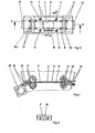
- Fig. 3 shows a plan view of the image window 4, from which it can also be seen that the image window 4 is part of a is a one-piece frame part 7,7a, 7b and part of the film transport path 8. Film transport rollers 17 are inserted into this film transport path 8. The film 6 running between the frame parts 7, 9 thus leads outside the image window area 4 into a film guide 18, as described, for example, in German patent application P.
- This film guide is provided at its outer ends with a receiving device 19, to which film cassettes 20 are attached or hooked, as described in German patent application P.
- Fig. 4 shows a section C-D of the film guide shown in Fig. 3.
- FIG. 5 shows a view of a receiving device 19 marked with x in FIG. 4.
- the upper part is designed such that even a strongly curved film has no surface contact.
- a film viewer supplemented by these measures, it is possible to use a film 6 provided with transparencies directly from the cassette via a dust-protected film guide path 18 with drive rollers 17 which engage in this path and act on the film edge, via the image window area 4 and a further corresponding film guide path without flushing film drive rollers into an empty cassette.
- the film drive and the position of the optics can be controlled as a structural unit by remote control.
- Fig. 6 shows a development of the adjusting device for the frame part, in which the connection of the two frame parts 7 and 9 is designed such that the second frame part 9 is adjustably connected to the first frame part 7.
- a spring 21, preferably a plate spring, rubber spring or the like, is arranged between the frame parts 7 and 9 which are arranged at a distance from one another.
- the inner edge 7c of the frame part 7 is chamfered to make adjustment easier and to improve glide. It is thus possible to make the projection 13 adjustable in terms of its distance from the contact plane without making this projection unstable.
- both frame parts 7, 9 are provided with one or more ventilation channels 15, which also cool the film in the area of the image window 4 from the lens side either directly or via deflection pieces 16.
- FIG. 8 shows a drive 22 for the rollers 17 provided with a concave drive axis 17a, with toothed belt drive 23, 24 and motor 25 (or crank).
- a worm gear can also be used.
- the concave design of the drive axle has the advantage that the transition for the film 6 is smooth and the edges of the film cannot touch anywhere.
- the frame parts 7a-c can also be manufactured individually and only assembled into a unit in the projector.
- the tapered surface of the part 7c also has a friction-reducing effect in that the film 6 lies only slightly against this part when the curvature is overcompensated.
- the parts 7, 9, 18 are adapted to the shape of the drive rollers and thus result in a smooth transition of the film 6 from the film guide into the rolls and vice versa.
Landscapes
- Physics & Mathematics (AREA)
- General Physics & Mathematics (AREA)
- Projection Apparatus (AREA)
Priority Applications (1)
| Application Number | Priority Date | Filing Date | Title |
|---|---|---|---|
| EP19810102870 EP0062688B1 (fr) | 1981-04-15 | 1981-04-15 | Guidage de film, notamment pour visionneuses, agrandisseurs, projecteurs et analogues |
Applications Claiming Priority (1)
| Application Number | Priority Date | Filing Date | Title |
|---|---|---|---|
| EP19810102870 EP0062688B1 (fr) | 1981-04-15 | 1981-04-15 | Guidage de film, notamment pour visionneuses, agrandisseurs, projecteurs et analogues |
Publications (2)
| Publication Number | Publication Date |
|---|---|
| EP0062688A1 true EP0062688A1 (fr) | 1982-10-20 |
| EP0062688B1 EP0062688B1 (fr) | 1987-01-07 |
Family
ID=8187660
Family Applications (1)
| Application Number | Title | Priority Date | Filing Date |
|---|---|---|---|
| EP19810102870 Expired EP0062688B1 (fr) | 1981-04-15 | 1981-04-15 | Guidage de film, notamment pour visionneuses, agrandisseurs, projecteurs et analogues |
Country Status (1)
| Country | Link |
|---|---|
| EP (1) | EP0062688B1 (fr) |
Citations (3)
| Publication number | Priority date | Publication date | Assignee | Title |
|---|---|---|---|---|
| AT260026B (de) * | 1964-11-14 | 1968-02-12 | Pentacon Dresden Veb | Vorrichtung zur Planführung des Filmes bei kinematographischen Geräten |
| DE2218793A1 (de) * | 1972-04-18 | 1973-10-31 | Braun Ag | Filmfuehrung in filmgeraeten |
| AT359831B (de) * | 1973-11-15 | 1980-12-10 | Polaroid Corp | Filmfuehrung fuer eine kinematographische kamera |
-
1981
- 1981-04-15 EP EP19810102870 patent/EP0062688B1/fr not_active Expired
Patent Citations (3)
| Publication number | Priority date | Publication date | Assignee | Title |
|---|---|---|---|---|
| AT260026B (de) * | 1964-11-14 | 1968-02-12 | Pentacon Dresden Veb | Vorrichtung zur Planführung des Filmes bei kinematographischen Geräten |
| DE2218793A1 (de) * | 1972-04-18 | 1973-10-31 | Braun Ag | Filmfuehrung in filmgeraeten |
| AT359831B (de) * | 1973-11-15 | 1980-12-10 | Polaroid Corp | Filmfuehrung fuer eine kinematographische kamera |
Also Published As
| Publication number | Publication date |
|---|---|
| EP0062688B1 (fr) | 1987-01-07 |
Similar Documents
| Publication | Publication Date | Title |
|---|---|---|
| DE68929490T2 (de) | Photographisches Kamerasystem und Filmpatronen | |
| DE19538679C2 (de) | Stereokamera | |
| DE19609727A1 (de) | Stereobildrahmen mit Blende und Auswahlvorrichtung | |
| DE2950861C2 (fr) | ||
| DE1597233B2 (de) | Photographischer Apparat mit Abtastbelichtung | |
| EP0062688B1 (fr) | Guidage de film, notamment pour visionneuses, agrandisseurs, projecteurs et analogues | |
| DE1287436B (de) | Vorrichtung zum selbsttaetigen Einstellen der Fuehrungselemente am Bildfenster einer mit auswcchselbaren Magazinen versehenen Schmalfilmkamera zur wahlweisen Verwendung von Filmstreifen unterschiedlicher Breite und Bildformate | |
| DE2359759C3 (de) | Filmlesegerät | |
| DE2621056A1 (de) | Mehrnormen-tonfilmwiedergabegeraet | |
| DE2734308C2 (de) | Kinematografische oder fotografische Kamera mit einem auf verschiedene Brennweiten einstellbaren Objektiv | |
| DE2453343A1 (de) | Filmkamera | |
| DE1171732B (de) | Filmfuehrung fuer fotografische Geraete, insbesondere Kinoprojektoren | |
| DE2118120C3 (de) | Einäugige Spiegelreflexkamera | |
| DE356206C (de) | Kopiervorrichtung fuer Kinofilme zur Veraenderung des Bildausschnittes | |
| DE2604770A1 (de) | Filmbetrachtungsgeraet | |
| DE3009791A1 (de) | Laufbildprojektor oder -betrachter mit einer stillstandsprojektionseinrichtung | |
| DE3904362A1 (de) | Laufbildkamera (stereo) | |
| DE2604771A1 (de) | Endlosfilm-kassette fuer ein filmbetrachtungsgeraet | |
| DE1817835B2 (de) | Diaprojektor | |
| DE2310870A1 (de) | Bildbetrachtungsgeraet | |
| DE2508959A1 (de) | Tonfilmaufnahmekamera | |
| DE7039208U (de) | Kleinbildkamera | |
| DE2242364A1 (de) | Fotografische kamera | |
| DE2649736A1 (de) | Filmtransporteinrichtung fuer laufbildprojektoren | |
| DE2904494A1 (de) | Kassettenvorrichtung fuer einen endlosen film |
Legal Events
| Date | Code | Title | Description |
|---|---|---|---|
| PUAI | Public reference made under article 153(3) epc to a published international application that has entered the european phase |
Free format text: ORIGINAL CODE: 0009012 |
|
| AK | Designated contracting states |
Designated state(s): AT BE CH DE FR GB IT LU NL SE |
|
| 17P | Request for examination filed |
Effective date: 19830420 |
|
| GRAA | (expected) grant |
Free format text: ORIGINAL CODE: 0009210 |
|
| AK | Designated contracting states |
Kind code of ref document: B1 Designated state(s): CH FR GB IT LI |
|
| ITF | It: translation for a ep patent filed | ||
| ET | Fr: translation filed | ||
| PLBE | No opposition filed within time limit |
Free format text: ORIGINAL CODE: 0009261 |
|
| STAA | Information on the status of an ep patent application or granted ep patent |
Free format text: STATUS: NO OPPOSITION FILED WITHIN TIME LIMIT |
|
| 26N | No opposition filed | ||
| PG25 | Lapsed in a contracting state [announced via postgrant information from national office to epo] |
Ref country code: GB Effective date: 19880415 |
|
| PG25 | Lapsed in a contracting state [announced via postgrant information from national office to epo] |
Ref country code: LI Effective date: 19880430 Ref country code: CH Effective date: 19880430 |
|
| GBPC | Gb: european patent ceased through non-payment of renewal fee | ||
| PG25 | Lapsed in a contracting state [announced via postgrant information from national office to epo] |
Ref country code: FR Free format text: LAPSE BECAUSE OF NON-PAYMENT OF DUE FEES Effective date: 19881229 |
|
| REG | Reference to a national code |
Ref country code: CH Ref legal event code: PL |
|
| REG | Reference to a national code |
Ref country code: FR Ref legal event code: ST |